Language selection

Search

Patent 2186438 Summary

Third-party information liability

Some of the information on this Web page has been provided by external sources. The Government of Canada is not responsible for the accuracy, reliability or currency of the information supplied by external sources. Users wishing to rely upon this information should consult directly with the source of the information. Content provided by external sources is not subject to official languages, privacy and accessibility requirements.

Claims and Abstract availability

Any discrepancies in the text and image of the Claims and Abstract are due to differing posting times. Text of the Claims and Abstract are posted:

  • At the time the application is open to public inspection;
  • At the time of issue of the patent (grant).
(12) Patent: (11) CA 2186438
(54) English Title: IMPROVED ELECTRICALLY CONDUCTIVE JOINT
(54) French Title: JOINT CONDUCTEUR
Status: Deemed expired
Bibliographic Data
(51) International Patent Classification (IPC):
  • H01R 4/58 (2006.01)
  • H01F 27/36 (2006.01)
  • H05K 9/00 (2006.01)
(72) Inventors :
  • STOYKO, MICHAEL T. (United States of America)
(73) Owners :
  • GEROME MANUFACTURING COMPANY INC. (United States of America)
(71) Applicants :
  • GEROME MANUFACTURING COMPANY INC. (United States of America)
(74) Agent: SMART & BIGGAR
(74) Associate agent:
(45) Issued: 2001-01-02
(22) Filed Date: 1996-09-25
(41) Open to Public Inspection: 1997-12-01
Examination requested: 1996-09-25
Availability of licence: N/A
(25) Language of filing: English

Patent Cooperation Treaty (PCT): No

(30) Application Priority Data:
Application No. Country/Territory Date
08/656,464 United States of America 1996-05-31

Abstracts

English Abstract


An electrically conductive joint and method of making,
comprising off-setting a portion of one end of a composite sheet
having a conductive layer and an insulative layer, bending a
part of the off-set portion into a first leg with the insulative
layer on the inside of the bend, bending an edge portion of a
second end of the sheet into a second leg with the insulative
layer on the outside of the bend, juxtaposing the two legs and
compressing them to form a continuous contact joint between the
conductive layers of the two ends, forming the sheet into a
magnetically-shielding housing with the joint disposed on the
inside of the housing.


French Abstract

Joint électriquement conducteur et méthode de fabrication de tels joints comportant les étapes suivantes: délimiter une partie d'une extrémité d'une feuille composite comportant une couche conductrice et une couche isolante; courber une section de la partie délimitée en une première patte, avec la couche isolante à l'intérieur de la courbe; courber une partie du bord d'une deuxième extrémité de la feuille en une deuxième patte, avec la couche isolante à l'extérieur de la courbe; juxtaposer les deux pattes et les comprimer de manière à former un joint à contact continu entre les couches conductrices des deux extrémités; former la feuille en une enceinte formant un blindage magnétique, avec le joint à l'intérieur de l'enceinte.

Claims

Note: Claims are shown in the official language in which they were submitted.


CLAIMS:

1. A method of forming an electrically conductive joint
in a sheet of material having top and bottom surfaces wherein
one surface is formed of an electrically conductive layer and
the other surface is formed of a layer of electrically
insulative material overlying and bonded to the electrically
conductive layer, comprising off-setting a portion of a first
end of said sheet material, said off-set portion extending
parallel to the top and bottom surfaces of said sheet material
and spaced from the remainder of said one end of said sheet
material, bending an edge part of the off-set portion into the
form of a first dependent leg forming an angle with the
remainder of the off-set portion and having said insulative
layer on the inside of the bend, bending an edge portion of a
second end of said sheet material into the form of a second
dependent leg forming an angle with the remainder of said
second end of said sheet material and having said insulative
layer on the outside of the bend, assembling the first and
second ends of the sheet material with the first and second
dependent legs juxtaposed to each other, and compressing the
assembly to collapse said first and second legs into a position
parallel to the top and bottom surfaces of the sheet material
whereby conductive surfaces of the first and second legs are in
face-to-face relationship forming a continuous electrically
conductive contact.

2. A method of making an electrically conductive joint
comprising off-setting a portion of one end of a composite
sheet having a conductive layer and an insulative layer,
bending a part of the off-set portion into a first leg with the
insulative layer on the inside of the bend, bending an edge
portion of a second end of the sheet into a second leg with the
insulative layer on the outside of the bend, juxtaposing the

6


two legs and compressing them to form a continuous contact
between the conductive layers of the two ends.

3. An electrically conductive joint formed of a sheet
material comprising a layer of conductive material and having
one surface of the sheet coated with an electrically insulative
layer, comprising a first end of the sheet having an off-set
portion and an edge part of the off-set portion bent into the
form of a first depending leg forming an angle with the
remainder of the off-set portion with the insulative layer on
the inside of the bend, a second end of the sheet having an
edge portion thereof bent into the form of a second dependent
leg forming an angle with the remainder of the second end of
the sheet with the insulative layer on the outside of the bend,
wherein, when the first and second ends of the sheet are
juxtaposed with the first and second legs in face-to-face
relationship with each other and compressed, the joint provides
continuous electrical contact between the electrically
conductive layers of the two ends of the sheet.

4. A hollow housing for surrounding and magnetically
shielding an electrical apparatus, comprising a sheet having an
electrically conductive layer and an electrically insulative
layer, first and second ends of the sheet forming a joint in
accordance with claim 3 whereby there is provided a continuous
electrical circuit about a periphery of the housing and
disposed inside the housing.

5. A joint according to claim 3, wherein the
electrically conductive layer is aluminium.

6. A joint according to claim 3, wherein the
electrically insulative layer comprises a polyvinyl chloride.

7

Description

Note: Descriptions are shown in the official language in which they were submitted.


286438
IMPROVED ELECTRICALLY CONDUCTIVE JOINT
BACKGROUND OF THE INVENTION
1. Field of the Invention
This invention relates to an electrically conductive joint,
and more specifically to a joint formed of a sheet of
electrically conductive material having one surface coated with
an electrically insulating coating, and which joint is useful in
the fabrication of magnetic shielding for electrical apparatus.
More specifically, the invention is directed to a magnetically-
shielding housing formed of such sheet, with the joint disposed
on the inside of the housing.
2. Related Prior Art
It is known in the prior art to provide hollow housings for
magnetic shielding of electrical apparatus. For example, U.S.
Patent No. 5,028,740 discloses such a housing comprising an
electrically conductive sheet, one surface of Which is coated
the an insulating material such as a paint, resin, etc. A
joint is formed by bending one end of a sheet of such material
into a hairpin shape and connecting that bent end to the other
end of the sheet by means of rivets or screws.
U:S. Patent No. 2,876,.275 shows a shielding panel
comprising a rigid member, such as plywood, provided with a
metal sheathing terminating in L-shaped portions which can be
locked together to provide continuity of electrical conductivity
from panel-to-panel.
U.S. Patent No. 3,340,587 discloses electromagnetic
shielding enclosures wherein panels are disposed in edge-to-edge
relationship, with U-shaped spring clips into which panel


CA 02186438 2000-OS-16
74445-30
flanges are inserted to provide an electrically continuous wall
of panels.
U.S. Patent No. 5,198,290 discloses an
electromagnetic shielding material comprising a flexible base
fabric, a first metallic film formed by flame spraying a metal,
such as Zn, on one side of the fabric, and a second metallic
film, such as A1 foil, formed on the other side of the fabric.
No joint is shown.
U.S. Patent No. 4,652,695 discloses a clip enclosing
an end of a knit mesh material and adapted to be installed
around the periphery of a door in a shielding enclosure to
maintain electrical continuity in the enclosure.
None of such prior art provides a joint in a
conductive metal sheet having one insulated surface, formed
only by bending the sheet.
This present invention is an improvement of that of
U.S. Patent 5,532,427 which is directed to a joint formed by
bending opposed edges of a sheet of conductive metal coated
with an electrically insulating material, wherein the sheet is
formable into a shielding container with the formed joint on
the outside of the container.
SUMMARY OF THE INVENTION
Therefore it is an object of the invention to provide
an electrically conductive inside joint of a sheet of
conductive material coated on one surface thereof with an
electrically insulating material merely by properly bending the
composite sheet material. This is done by providing one end of
the sheet with an off-set portion and then bending an end part
of the off-set portion into the form of a first depending leg
with the insulating material on the inside of the leg. The
2


CA 02186438 2000-OS-16
74445-30
other end of the sheet is bent into the form of a second
depending leg with the insulating material on the outside of
the leg. The two depending legs then are juxtaposed and the
two ends compressed into the form of a joint wherein
electrically conductive surfaces are in face-to-face contact,
providing continuity of electrical conductivity and the thus-
formed joint is disposed on the inside of a shielding container
formed from the sheet.
In summary, this invention seeks to provide a method
of forming an electrically conductive joint in a sheet of
material having top and bottom surfaces wherein one surface is
formed of an electrically conductive layer and the other
surface is formed of a layer of electrically insulative
material overlying and bonded to the electrically conductive
layer, comprising off-setting a portion of a first end of said
sheet material, said off-set portion extending parallel to the
top and bottom surfaces of said sheet material and spaced from
the remainder of said one end of said sheet material, bending
an edge part of the off-set portion into the form of a first
dependent leg forming an angle with the remainder of the off-
set portion and having said insulative layer on the inside of
the bend, bending an edge portion of a second end of said sheet
material into the form of a second dependent leg forming an
angle with the remainder of said second end of said sheet
material and having said insulative layer on the outside of the
bend, assembling the first and second ends of the sheet
material with the first and second dependent legs juxtaposed to
each other, and compressing the assembly to collapse said first
and second legs into a position parallel to the top and bottom
surfaces of the sheet material whereby conductive surfaces of
the first and second legs are in face-to-face relationship
forming a continuous electrically conductive contact.
3


CA 02186438 2000-OS-16
74445-30
BRIEF DESCRIPTION OF THE DRAWINGS
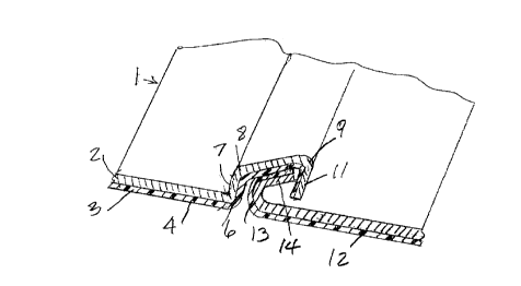
Fig. 1 is an isometric view of both ends of the sheet
wherein one of the opposed edges of the sheet is provided with
an off-set portion forming a first dependent leg and the other
opposed edge of the sheet is bent in an angle forming a second
dependent leg;
Fig. 2 is an isometric view of the two ends of the
sheet assembled with the first and second legs juxtaposed and
compressed into the form of a final joint formed on the inside
3a


2186438
r
of a hollow, magnetic-shielding housing formed of the sheet
material.
DESCRIPTION OF PREFERRED
Fig. 1 shows a first stage of formation of the inventive
joint wherein a sheet 1 comprises an electrically conductive
layer 2 e.g. of metal such as aluminum or copper, and an
electrically insulative layer 3, e.g. of a polyvinyl chloride
(PVC), shown in hatched lines. A first end 4 of the sheet 1 is
bent as at 6, providing an off-set portion 7.
Off-set portion 7 is bent as at 8 and 9, forming a first
dependent leg 11 at an acute angle to the remainder of the off-
set portion and wherein the insulative layer 3 is on the inside
of the bend.
In Fig. 1 there also is shown a second end 12 of the
composite sheet, bent as at 13, providing a second dependent leg
14 forming an acute angle with the remainder of the second end
of the sheet and wherein the insulative layer 3 is on the
outside of the bend.
As shown in Fig. 2, when end 4 and end 12 of the formed
sheet are assembled, the first dependent leg 11 is juxtaposed to
the second dependent leg 14 and, when this assembly is
compressed, the collapsed dependent legs 11 and 14 provide
continuous metal-to-metal contact, as at 16.
As also shown in Fig. 2, a hollow housing denoted generally
by the numeral 17 is formed with ends 4 and 12 of the sheet
material connected with a formed joint 18, disposed on the
4

2186438
r
inside of the housing, leaving only a narrow seam 19 on the
outside of the housing. such a housing is useful for
surrounding and magnetically shielding an electrical apparatus,
and, with the seam on the inside of the housing, makes an
aesthetically pleasing presentation.
The joint of the invention. requires no separate joining
means such as rivets, screws, clips or the like but is formed
only by bending and assembling the ends of the composite sheet
material and compressing the assembly thereby locking the ends
l0 in place and forming a continuous electrical contact between the
compressed ends of the sheet.
5

Representative Drawing
A single figure which represents the drawing illustrating the invention.
Administrative Status

For a clearer understanding of the status of the application/patent presented on this page, the site Disclaimer , as well as the definitions for Patent , Administrative Status , Maintenance Fee  and Payment History  should be consulted.

Administrative Status

Title Date
Forecasted Issue Date 2001-01-02
(22) Filed 1996-09-25
Examination Requested 1996-09-25
(41) Open to Public Inspection 1997-12-01
(45) Issued 2001-01-02
Deemed Expired 2004-09-27

Abandonment History

There is no abandonment history.

Payment History

Fee Type Anniversary Year Due Date Amount Paid Paid Date
Request for Examination $200.00 1996-09-25
Application Fee $0.00 1996-09-25
Registration of a document - section 124 $0.00 1997-03-13
Maintenance Fee - Application - New Act 2 1998-09-25 $50.00 1998-07-20
Maintenance Fee - Application - New Act 3 1999-09-27 $100.00 1999-08-16
Maintenance Fee - Application - New Act 4 2000-09-25 $100.00 2000-08-17
Final Fee $300.00 2000-09-13
Maintenance Fee - Patent - New Act 5 2001-09-25 $150.00 2001-08-02
Maintenance Fee - Patent - New Act 6 2002-09-25 $150.00 2002-09-05
Owners on Record

Note: Records showing the ownership history in alphabetical order.

Current Owners on Record
GEROME MANUFACTURING COMPANY INC.
Past Owners on Record
STOYKO, MICHAEL T.
Past Owners that do not appear in the "Owners on Record" listing will appear in other documentation within the application.
Documents

To view selected files, please enter reCAPTCHA code :


To view images, click a link in the Document Description column. To download the documents, select one or more checkboxes in the first column and then click the "Download Selected in PDF format (Zip Archive)" or the "Download Selected as Single PDF" button.

List of published and non-published patent-specific documents on the CPD .

If you have any difficulty accessing content, you can call the Client Service Centre at 1-866-997-1936 or send them an e-mail at CIPO Client Service Centre.


Document
Description 
Date
(yyyy-mm-dd) 
Number of pages   Size of Image (KB) 
Cover Page 2000-12-04 1 45
Cover Page 1997-12-15 1 46
Description 1997-01-22 5 114
Cover Page 1998-08-25 1 46
Abstract 1997-01-22 1 13
Cover Page 1997-01-22 1 11
Representative Drawing 2000-12-04 1 7
Claims 1997-01-22 3 78
Drawings 1997-01-22 1 14
Representative Drawing 1997-12-15 1 8
Description 2000-05-16 6 180
Claims 2000-05-16 2 97
Abstract 2001-01-02 1 13
Drawings 2001-01-02 1 14
Description 2001-01-02 6 180
Prosecution-Amendment 1999-12-02 2 3
Correspondence 2000-09-13 1 39
Prosecution-Amendment 2000-05-16 7 261
Assignment 1996-09-25 7 290
Correspondence 1996-10-29 1 40