Note: Descriptions are shown in the official language in which they were submitted.
2~g~52
.
ROTATING FRRn APPARATUS FOR ROD--TTRR ~R~I~rRs
This invention relates to a rotating feed apparatus for
rod-like articles, and is particularly for feeding filter
tipped cigarette tubes received from an axial feed supply to
a laterally moving conveyor. Particularly it is intended to
feed the tubes in a single layer onto the CUIIV~YUL.
Cigarette tubes are formed by rolling a long strip of
paper into a tube, glue being applied along one edge to cause
an overlap to bond. Filter members are deposited on the paper
strip at predet~rmin~d intervals. Also, if desired, a cork or
similar length of material is applied to what is to be the
outside of the tube, at positions for the filters. Normally
the production is continuous and in effect the tubes are formed
"back-to-back", being cut at the centre point in the length of
the filter.
Conventionally, the separated tubes drop onto UUIlV~yu
fed between laterally spaced side walls, which form ~hlnnPl~.
The tubes are then fed into large portable hoppers which in
turn are positioned on a further machine. Here the tubes fall
from the bottom of the hopper into boxes.
Due to the unbalanced nature of filter tipped tube6, it
is a problem that tubes do not fall correctly onto the
conveyors. They can be damaged and also cause other problems.
In a modification, the tubes can be lifted from the
~h~nn~l~ manually and dropped into boxes. Again, any
incorrectly orientated tubes can cause problems.
It is desirable that when the tubes are fed onto a
conveyor, the tubes should "rest" against each other without
~ 2186~S2
pyramiding or bunching. This is particularly so for
satisfactory operation of packaging arrAng L5, If the
movement of the tubes is not controlled, the ~lnhAlAnr~d nature
of the filter tipped tubes causes undesirable misorientation
of the tubes. As an example, tubes can become turned by 20-
to 30-, inclined across the ~ V~y~.
In one embodiment of the present invention, the tubes are
fed from the tubc - k;ng apparatus, after cutting into
individual tubes, to a rotating drum-like feeding member. A
plurality of axially extending grooves are formed in the
periphery of the drum. Normally the groves have a length
somewhat longer than two tubes, and alternate grooves have a
stop member adjacent the mid-point in their length. The tubes
are fed into successive grooves, one tube positioned in a first
part of a groove, against a stop, the next tube positioned in
the further part of the next groove. This pattern repeats.
As the drum rotates, a flap member extends around the
periphery holding the tubes in the grooves. At, or near, the
bottom of rotation, the tubes fall out onto the conveyor. The
conveyor is divided into two side-by-side portions, by a
divider.
Holes can be formed in the bottom of the grooves, and a
pneumatic suction applied at the inlet side of the drum to slow
down the speed of the tubes in the grooves. The suction is
applied for the upper rear portion of the periphery. A
further, high flow suction is applied to the ends of the
grooves at the side of the drum remote from the inlet. This
ensures that the tubes in the further parts of the grooves are
against a rim of the drum.
In a further ~ nt of the invention, there is
218~5~2
provided advancing means for moving a pr~t~rm;n~d number of
tubes to a holding position and means for transferring the
tubes at the holding position into a packaging member.
The invention will be readily understood by the following
description of certain embodiments, by way of example, in
conjunction with the a~ -nying drawings, in which:
Figure 1 is a front view of one form of a drum member;
Figure 2 is a side view of a drum member, in the direction
of arrow A in Figure 1:
Figure 3 is a cross-section on the line 3-3 of Figure 2,
to a larger scale, at the inlet side of the drum, illustrating
a suction arrangement;
Figure 4 is a cross-section to a larger scale of part of
a drum on the line 4-4 of Figure 1;
Figure 5 diagrammatically illustrates, in plan form, one
form of packaging apparatus for packing tubes into a box;
Figure 6 is a side view in the direction of arrow 6 in
Figure 5; and
Figures 7 and 8 are end views illustrating the operation
of receptacle or containment members for receiving tubes and
accepting of box or similar member.
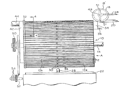
In Figures 1 and 2, a rotatable drum 10 has a plurality
of axially extending channel-shaped grooves 12, at the
periphery. The grooves have a semi-circular profile to suit
the tubes to be fed. The drum is mounted on shaft 14 for
~ ~186~52
indicated by the arrow 16.
In Figure 1 is shown a feed wheel 18, which feeds the
individual tubes from a supply tube 20 which is at the end of
the tube king apparatus, not shown.
Beneath the drum 10 is a conveyor 22 moving as indicated
by the arrow 24. A flap 26 extends around the rear of the
drum. A dividing member 28 i8 positioned over the conveyor.
In the example, and as seen in Figure 2, alternate grooves
12 have a stop 30 positioned adjacent the mid-point. Each stop
is positioned such that its peripheral edge nearest the feed
wheel 18 is at the centre point, or slightly towards the feed
wheel. The stops divided alternate grooves into two parts, 12a
and 12b in Figure 1. In operation, as the drum revolves, tubes
are fed by the wheel 18 into the grooves. One tube will go,
for example, into a groove having a stop. In this case, the
tube moves to the stop and is held in part 12a. The tube fed
to the next groove will move right across the groove and will
be positioned against a rim 32, aligned with the part 12b of
adjacent grooves.
At the upper part of the periphery of the drum, at the
inlet end, in sliding contact with the drum side surface, is
a channel member 34 open in the side in contact with the drum.
A suction connection is made at 36. A suction is applied to
holes 38 formed in the bottom of the grooves via axial bores
40 beneath the grooves 1 (Fig. 3). A further channel member
42 is in sliding contact with the rim 32. This member can
extend for the majority of the rear periphery of the drum and
creates a high flow of air along the grooves to ensure that the
tubes in the parts 12a of the grooves are against the rim 32,
a suction connection shown at 44.
~ 2186~52
Figure 3 illustrates an arrangement for applying the
suction to the holes 38. Behind each groove 12 is a transverse
or axially extending bore 40, with which the holes 38 communi-
cate. The channel member 34 extends for a short arc at a top
rear position on the drum. The cross-section of the channel
member 34 is shown in Figure 3. The cross-section of channel
member 42 is similar to that of channel member 34. The channel
member 42 extends at the rear periphery of the drum, as shown
in dotted outline in Fig. 2. Figure 4 shows holes 46 in the
10rim 32 through which air i5 drawn into the channel member 42.
In a particular arrangement, the wheel 18 propels the
tubes at a alightly faster speed than that at which they are
fed through tube 20. This ensures a slight separation between
the ends of succes6ive tubes, reducing possibility of damage.
As the wheel 18 feeds the tubes, the drum is rotating.
Spiral grooves 18' are formed in the periphery of the wheel 18
so that a sideways or lateral motion is given to the tube, in
20addition to the axial movement, so that the tubes enter the
groove 12 smoothly and without damage. A suction can be
applied to the grooves 18' in the wheel 18 to ensure prop~ll ing
of the tubes by the wheel. As an example, suction can be
applied via pipe 48 via a central bore 49 and radial connec-
tions 51.
The drum is rotated via a toothed belt gear 50, driven by
toothed belts, not shown, from a drive shaft. A further shaft
52, having a rotation related to that of the shaft 12 and thus
30of the drum 10, carrles cam members 54 which can be used to
actuate counters, via switches 56, relating to the number of
tubes delivered to the conveyor 22. As the drum rotates, the
tubes fall sequentially onto the moving conveyor 22 in a single
layer, a layer on each side of the divider 28. As the drum
2186~2
.
approaches quite near to the conveyor, the tubes are correctly
orientated across the COIIV~Y~L.
The speed relationship between the drum and the CUIIV~YUL
22 is important, to ensure that the tubes fall on the CU~IV~YUL
in a single layer and resting against each other to ensure that
the tubes extend across the ~ullv~yOL with axes normal to the
direction of ~ of the conveyor. Therefore, the rotation
of the drum is such that the tubes are discharged, or fall,
from the drum to form the single layer, in immediate adjacent
positions. If the drum i5 too fast relative to the cullveyuL
then tubes will form more than one layer, at least at times.
Similarly, if the drum is too slow, gaps will occur between
tubes, and tubes can become misaligned.
The description above is specific to cigarette tubes but
it can very well be appreciated that the apparatus can feed
other rod-like members. Also, although a drum having the
facility to feed two rows of tubes onto a r_u..v~yuL has been
described, it is possible to feed only one row. In this case
there is no need for the stop 30.
Figures 5 and 6 diagrammatically illustrate one form of
packing apparatus, for packing tubes on ~UIlV~yuL 22 into boxes.
A support base 110 mounts a frame work having spaced apart
parallel frame members 112. Between the frame members 112 is
mounted the conveyor 22. In Figure 6 is shown the feed drum
10, positioned over one end of the curlveyuL.
The conveyor 22 moves as indicated by the arrow C of
Figure 5, and the drum 10 rotates as indicated by arrow D,
Figure 6. Cigarette tubes are fed to the top of the drum, into
the axially extending grooves 12 in the drum periphery and are
carried round and dropped in a single layer on the uOIlv~y~L.
~ 2186~2
Curved flap 32 extends round the rear of the drum to ensure the
cigarette tube5 remain in the grooves, as illustrated in Figure
2.
In the example of Figures 5 and 6, two rows of tubes are
deposited on the conveyor, which is divided into two sections
by a central divider 122. A support member 130, pivotally
mounts a split pivoted flap 132. The flap is actuated by an
actuator 134, for example a pneumatic piston, and is divided
laterally into two parts, a part on each side of the divider
122. The lower end of the flap is pivoted down to just clear
the conveyor when the actuator 134 is operated.
Next in line along the conveyor is a central rod 140
supported at one end from the frame members 112 by support
member 130 and at the other end by support 142. Slidably
mounted on the rod 140, by means of a central member 144, are
two pusher members 146. The pusher members are vertically
moved, up and down, by actuators, for example pneumatic rams
148. The central member 144, with the pusher members 146, is
reciprocated along the rod 140, for example by pneumatic ram
150.
Starting generally at the support 142 there is defined an
accumulating or holding position, indicated at 160, one on each
side of the divider. The divider 122 ends at the support 142
and in the centre are positioned two laterally movable ejecting
members 162. The ejecting members are reciprocated outwardly
in the example by pneumatic rams 164. The side frame members
112 are reduced in height at the holding positions and the gaps
filled by blocking members 166 which reciprocate back and
forth, being actuated by, for example, pneumatic rams 168. The
rear walls of the holding positions are defined by static walls
170. The holding positions are dimensioned to hold a prede-
~ 2186552
t~rm;ned number of cigarette tubes, for exampler two hundred.
Illustrated in Figure 5, and also Figures 7 and 8, is one
form of transfer means and cont~i L means. Pivotally
mounted on the frame member 112, adjacent the wall 170, are
trough-shaped cont~; L members 172. The trough members are
open at one side, facing towards the holding positions. The
trough members can pivot outwardly about a pivot axis 174. The
trough members can also be rotated about a horizontal axis
extending laterally, whereby any articles in a trough member
will fall out through the open side. A first, pivotal
position, is shown in dotted outline at 172' and a second,
rotated position, is shown in dotted outline at 172".
Positioned below the outward pivoted and rotated position
of the member 172 is a vertically movable table 180, indicated
in dotted outline in Figure 6 and seen more clearly in Figures
7 and 8. The tables 180 are mounted on brackets 182 extending
from frame 184. The tables are mounted on rods 186 vertically
reciprocated, for example, by cylinders 188.
The actuation is typically as follows. The tubes are
pushed laterally, by the injecting members 162, into the
containment member 172. Once the injecting members have pushed
the tubes into the conf~; L members, the cont~i - t members
rotate to bring the open side nrpe ~ L. The cont~i L
member then pivots round to 172'. An empty box is positioned
over the contA;r- L member and then the contli L member,
with the box and tubes, rotates so that the contA;r~ ~ member
open side is now downwards - position 172".
The tables 180 have elevated as in Figure 7, as the
containment members, and boxes pivot round. The tables are
such a height that as the cont~ir- L members rotated down, the
~ ~186552
boxes rest on the tables. The tables move down and the boxes,
filled with tubes, move from the cont~i ~ member. The boxes
are shown at 200 in Figure 8.
While the containment members are pivoting and rotating,
the injecting members 162 retract, the blocking members 166
move to close off the sides of the holding positions, the
pusher members 146 have retracted and the pivoted flap is in
the up position, for a further supply of tubes.