Note: Descriptions are shown in the official language in which they were submitted.
2 1 86~20
-
PLANT SPROUTING POT
FIELD OF THE l~v~NlION
The present invention relates to a plant sprouting
pot and more particularly to a pot for sprouting seeds,
seedlings, or cuttings of plants and growing plants such
as ginseng plants.
BACKGROUND OF THE lNV~N'l'lON
The prior art abounds with pots specifically designed
for sprouting and growing plants of numerous varieties
from seeds, seedlings or plant cuttings. In order for
sprouts and plants to be grown from seeds, seedlings or
plant cuttings, it is essential for the seeds, seedlings
or plant cuttings to be subjected to suitable moisture and
temperature conditions so as to encourage the natural
sprouting of the seeds, seedlings or plant cuttings and
the growing of the plants. The following U. S. patents
are exemplary of such prior art pots: 2,138,188 (Morley);
3,704,545 (Reisen); 4,291,493 (Monson); 5,094,033 (Drew);
and 5,375,372 (Lee et al.).
The Morley patent discloses a seedling cultivating
flowerpot having a container for receiving soil, a glass
cover or dome with an opening therein for allowing air to
enter the pot when desired, and a stopper for closing the
opening in the cover or dome to preclude air entering the
pot when such is not desired. The Reisen patent discloses
a plastic container for plants having a pot for a bulb and
surrounding earth, a coupling rosette that acts as a lid
2 1 86920
for the pot, and a cover for the coupling rosette and pot.
The Monson patent discloses an apparatus for sprouting
seeds including an outer container, an inner container in
which seeds are sprouted, a plurality of slits in the
inner container for allowing excess moisture to drip from
the inner container into the outer container, a cover or
dome having a plurality of openings therein for permitting
air to enter the inner container, and a nesting structure
which provides an air passage between the inner and outer
containers. The Drew patent discloses a seed germinator
including a soil retention container in which seeds are
placed, and a cover having a depression in its top surface
with a small hole at the lowest point of the depression so
as to allow a liquid placed in the depression to drip
through the small hole and fall into the soil retention
container. The Lee et al. patent discloses a tissue and
seedling culture bottle having a lower container for
housing a culture medium and seedlings, a cover or dome
including one or more air passages, at least one of which
has sterilized absorbent cotton therein, to allow air and
gas produced in the bottle during seedling culture or
growth to escape from the bottle while preventing bacteria
and viruses from entering the bottle.
The prior art pots specifically designed for the
sprouting and growing of plants, including those discussed
above, have generally suffered from numerous deficiencies
and disadvantages particularly in that their structures
did not allow adequate moisture to get to the seeds,
2 1 86920
seedlings, or plant cuttings, together with the plant
roots and the soil especially when the cover was in
position over the container which housed the soil and
seeds, seedlings or plant cuttings.
The instant invention relates to a plant sprouting
pot which overcomes the deficiencies or disadvantages of
prior art plant sprouting pots in that moisture is
supplied to the seed or plant on a continuous and
relatively consistent basis from a supply reservoir
incorporated in the pot.
SUMMARY OF THE lNV~N'l'lON
In accordance with the present invention a plant
sprouting pot is provided which continuously and
consistently supplies moisture to seeds, seedlings, plant
cuttings, and the soil or roots of plants therein to
enhance the germination and growth of the seeds,
seedlings, plant cuttings, and plants. The plant
sprouting pot is adapted to rest upon a surface such as a
table, or to be housed in an opening within a shelf or the
like, or to hang from an overhead structure such as a hook
in the ceiling of a room.
The plant sprouting pot is genera~ly comprised of an
outer container, a connecting ring, an inner container
having soil therein, a reinforcing ring, and a cover or
dome. One embodiment of the invention also includes a
support collar for supporting the inner container. When
assembled with seeds, seedlings, plant cuttings or plants
21 86923
embedded in the soil within the inner container and a
liquid within the outer container, as the seeds, seedlings
or plant cuttings germinate and the plants grow, moisture
captured in the outer container is drawn from the outer
container through numerous, small, spaced, openings in the
inner container to the soil and seeds, seedlings or plant
cuttings or roots of plants within the inner container on
a continuous and consistent basis.
Accordingly, it is an object of the present invention
to provide an improved pot for furnishing moisture to
seeds, seedlings, plant cuttings or plants embedded in
soil in the pot.
It is another object of the present invention to
provide an improved pot for furnishing moisture to seeds,
seedlings, plant cuttings or plants embedded in soil in
the pot on a continuing and consistent basis.
It is a further object of the present invention to
provide an improved pot which is simple and inexpensive in
construction, which may be easily used at home or in other
environments, for sprouting seeds, seedlings, plant
cuttings and growing plants.
These objects as well as other objects, advantages
and features of the present invention will become more
readily apparent from the following specification when
taken in conjunction with the accompanying drawings.
BRIEF DESCRIPTION OF THE DRAWINGS
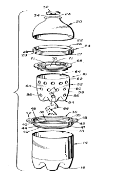
Figure 1 is an exploded, perspective, view of the
2 1 86920
plant sprouting pot of the present invention.
Figure 2 is a front elevational, partially broken
away, view of the plant sprouting pot of the present
invention having soil, a plant, and water therein.
5Figure 3 is a perspective view of the plant sprouting
pot of the present invention having a plant growing
therein and with the cover removed therefrom.
Figure 4 is a perspective view of the inner container
of the plant sprouting pot of the present invention having
the support collar or sleeve and a single wick secured
thereto. Figure 5 is a front elevational view,
partially broken away, and in section, showing the details
of the support collar or sleeve.
Figure 6 is a front elevational view, partially
broken away, and in section, showing the details of the
connecting ring.
Figure 7 is a top plan view showing the details of
the connecting ring.
Figure 8 is a front elevational view, partially
broken away, and in section, showing the details of the
reinforcing ring.
Figure 9 is an exploded, perspective, view of a
second embodiment of the plant sprouting pot of the
present invention, but not including its cover or dome
with reinforcing ring.
Figure 10 is a front elevational, partially broken
away, view of the second embodiment of the plant sprouting
pot of the present invention with the cover or dome
21 86920
removed therefrom.
Figure 11 is a front elevational view, partially
broken away, and in section, showing the details of the
connecting ring used in the second embodiment of the
present invention.
Figure 12 is a top plan view showing the details of
the connecting ring used in the second embodiment of the
present invention.
DETAILED DESCRIPTION OF THE PREFERRED EMBODIMENT
Referring now to the drawings, particularly Figure 2
thereof, reference numeral 10 generally designates the
plant sprouting pot of the present invention.
Referring now to Figures 1 and 2, plant sprouting pot
10 generally comprises an outer container 12, a connecting
ring 36, an inner container 52, a support collar 68, a
reinforcing ring 24, and a cover or dome 20. Outer
container 12 includes a lower section 14 having a closed
bottom 16; an upper opening 18; and a hollow cover or dome
20 including a lower opening 22, an upper opening 23, and
a reinforcing ring 24. As best shown in Figure 8,
reinforcing ring 24 includes a central opening 26, a first
annular shoulder 27, a second annular shoulder 29, an
annular external groove 28, and an upper tapered portion
30. Reinforcing ring 24 is pressure fitted or secured by
any conventional adhesive within the lower opening 22 of
cover or dome 20. As best shown in Figure 1, a cap 32
having a central hole 34 therein is mounted in the upper
opening 23 of cover or dome 20 by any conventional means
21 86920
such as threads or adhesives. A ring 36 connects lower
section 14 and cover or dome 20 of outer container 12, and
as best shown in Figures 1, 6 and 7, ring 36 includes a
central opening 38, an internal annular shoulder 39, an
upper annular portion 40, a pair of handles 42 secured to
the upper annular portion 40, a shoulder 47 which is a
part of the upper wall of external annular groove 46, and
a lower annular portion 44 having the external annular
groove 46, and an internal annular shelf 48. Each of
handles 42 has an opening 43 therein for purposes to be
later explained.
As best seen in Figures 1 and 4, inner container 52
includes a lower portion 54 having a plurality of
relatively small holes 56 therein; an intermediate portion
58 having a plurality of relatively small holes 60
therein; an upper portion 62 having an upper opening 64
therein; and one or more wicks 66 mounted in a respective
hole 56 in lower portion 54. As best seen in Figures 4
and 5, a support collar 68 is provided for supporting
inner container 52. Support collar 68 has a central
opening 70 therein, spaced tabs 71, an upper annular
protrusion 72, and, as best seen in Figure 5, a lower
tapered portion 76, an external annular groove 78, and an
external annular raised portion 79. The support collar 68
is press fitted into the upper opening 64 of upper portion
62 of inner container 52 to form a part of inner container
52.
As best shown in Figures 2 and 3, inner container 52
2 1 86920
is filled with soil 80 for growing a plant 82 therein.
Water 84 is provided in the lower section 14 of sprouting
pot 10 for feeding the plant 82.
As best seen in Figure 2, outer container 12 is
substantially larger than inner container 52 to provide a
gap therebetween for housing moisture and to permit the
roots of growing plants to enter the holes 56 and 60 of
inner container 52 and exit the holes 56 and 60 into the
gap between the outer wall of inner container 52 and the
inner wall of outer container 12. The numerous holes 56
and 60 in the inner container 52 permit the roots to
expand and moisture to enter the soil consistently and
continuously and keep the moisture within the soil at a
generally low level. One or more wicks 66 might be
provided to feed moisture from the outer container 12 into
the soil 80 within inner container 52; however it has been
found that the use of wicks are not essential for moisture
to reach soil 80 and the roots of the plants.
The plant sprouting pot 10 of the present invention
is assembled to the condition generally depicted in Figure
2 by first placing water or some premixed solution into
outer container 12 such that most, if not all, of the
spaced holes 56 in inner container 52 would be below the
level of the water or premixed solution; the connecting
ring 36 is then inserted into the upper opening 18 of
lower section 14 of outer container 12 such that the
external raised annular portion 44 of connecting ring 36
tightly engages the inner wall of lower section 14 of
2 1 86920
outer container 12 adjacent its upper opening 18 with the
shoulder 47 of connecting ring 36 being in engagement with
the edge of upper opening 18 of lower section 14 of outer
container 12; the support collar 68 is then inserted into
the upper opening 64 of inner container 52 such that the
raised annular portion 79 of support collar 68 tightly
engages the inner walls of inner container 52 adjacent its
upper opening 64; the inner container 52 (with soil 80 and
seeds, seedlings, or plant cuttings embedded therein) is
then inserted into the connecting ring 36 to a position
where the upper annular protrusion 72 of support collar 68
rests upon the annular internal shelf 48 of connecting
ring 36 and the lower holes 56 of inner container 52 are
below the level of water or premixed solution in the lower
section 14 of outer container 12; and the lower portion of
the cover or dome 20 (with the reinforcing ring 24 already
press-fitted into the cover or dome 20 adjacent its lower
opening 22 and the cap 32 already secured to cover or dome
20) is then inserted into the central opening 38 of
connecting ring 36 until the lower portion (adjacent the
reinforcing ring 24 in lower opening 22) of cover or dome
20 engages and rests upon the internal annular shoulder 39
of connecting ring 36. When assembled, and if later
needed, additional water or premixed solution can be added
to the sprouting pot 10 through the hole 34 in cap 32 or
added by removing the cover or dome 20.
The engagement of the upper annular protrusion 72 of
support collar 68 with the annular internal shelf 48 of
21 86q20
connecting ring 36 and the engagement of the lower portion
(adjacent lower opening 22) of cover or dome 20 with the
internal annular shoulder 39 of connecting ring 36 seals
the sprouting pot 10 with air entering the pot 10 through
the hole 34 in cap 32. Of course, air will always exist
in the gap (space) between the inner container 52 and
outer container 12. If desired, the hole 34 in cap 32 can
be closed by a plug or the like.
A second embodiment of the sprouting pot is depicted
in Figures 9-12 with like reference numerals referring to
like parts. The embodiment depicted in Figures 9-12
differs from that disclosed in Figures 1-8 primarily in
the combination of the features of the support collar and
connecting ring into one part which is designated in the
second embodiment as a connecting ring and given reference
numeral 90. In this combination, the support collar 68 of
the embodiment depicted in Figures 1-8 is totally
eliminated and the shelf 48 of connecting ring 36 of the
embodiment depicted in Figures 1-8 is totally eliminated.
While not shown in Figures 9-12, the second embodiment
includes a cover or dome 29, reinforcing ring 24 and cap
32 as shown in the first embodiment (Figures 1-8).
Referring now to Figures 9-12, the second embodiment
of the plant sprouting pot comprises an outer container
12, a connecting ring 90, an inner container 52, a
reinforcing ring 24, and a cover or dome 20. Outer
container 12 includes a lower section 14 having a closed
bottom 16; an upper opening 18; and a hollow cover or dome
lQ
2186q20
-
20 including a lower opening 22, an upper opening 23, and
a reinforcing ring 24. Ring 90 connects lower section 14
and cover or dome 20 of outer container 12, and also
supports inner container 52. As best shown in Figures 11
and 12, ring 90 includes a central opening 38, an internal
annular shoulder 39, an upper annular portion 40, a pair
of handles 42 secured to the upper annular portion 40, a
shoulder 47 which is a part of the upper wall of external
annular groove 46, and a lower annular portion 44 having
the external annular groove 46. Each of handles 42 has an
opening 43 therein for purposes to be later explained.
As best seen in Figure 9, inner container 52 includes
a lower portion 54 having a plurality of relatively small
holes 56 therein; an intermediate portion 58 having a
plurality of relatively small holes 60 therein; an upper
portion 62 having an upper opening 64 therein; and one or
more wicks 66 mounted in a respective hole 56 in lower
portion 54. The ring 90 is press fitted into the upper
opening 64 of upper portion 62 of inner container 52.
As best shown in Figure 10, inner container 52 is
filled with soil 80 for growing a plant therein. Water 84
is provided in the lower section 14 of sprouting pot 10
for feeding the plant embedded in the soil 80.
As best seen in Figure 10, outer container 12 is
substantially larger than inner container 52 to provide a
gap therebetween for housing moisture and to permit the
roots of growing plants to enter the holes 56 and 60 of
inner container 52 and exit the holes 56 and 60 into the
2 1 86920
gap between the outer wall of inner container 52 and the
inner wall of outer container 12. The numerous holes 56
and 60 in inner container 52 permit the roots to expand
and moisture to enter the soil consistently and
continuously and keep the moisture within the soil at a
generally low level. One or more wicks 66 might be
provided to feed moisture from the outer container 12 into
the soil 80 within inner container 52; however it has been
found that the use of wicks are not essential for moisture
to reach soil 80 and the roots of the plants.
The plant sprouting pot of the second embodiment of
the present invention is assembled to the condition
generally depicted in Figure 10 by first placing water or
some premixed solution into outer container 12 such that
most, if not all, of the spaced holes 56 in inner
container 52 would be below the level of the water or
premixed solution; the connecting ring 90 is then inserted
into the upper opening 64 of inner container 52 (with soil
80 and seeds, seedlings or plant cuttings already embedded
in soil 80) such that the raised annular portion 44 of
connecting ring 90 tightly engages the inner walls of
inner container 52 adjacent its upper opening 64 to secure
the connecting ring 90 to inner container 52; then the
connecting ring 90 and inner container 52 are inserted
into upper opening 18 of the lower portion 14 of outer
container 12 until such time that the shoulder 47 of
connecting ring 90 engages the wall of lower section 14 of
outer container 12 which surrounds upper opening 18 at
2186920
-
which time holes 56 and 60 of inner container 52 are below
the level of water or premixed solution in the lower
section 14 of outer container 12; and the lower portion of
the cover or dome 20 (with the reinforcing ring 24 already
press-fitted into the cover or dome 20 adjacent its lower
opening 22 and the cap 32 already secured to cover or dome
20) is then inserted into the central opening 38 of
connecting ring 90 until the lower portion (adjacent the
reinforcing ring 24 in lower opening 22) of cover or dome
20 engages and rests upon the internal annular shoulder 39
of connecting ring 90. When assembled, and if later
needed, additional water or premixed solution can be added
to the sprouting pot 10 through the hole 34 in cap 32.
The sprouting pot 10 can be used when seated upon a
flat surface such as a table or window sill, placed in a
rack having openings for supporting one or more of the
sprouting pots 10, or it can be suspended from the ceiling
of a room or porch by inserting and tying the ends of a
support filament (not shown) through each of the holes 43
in handles 42 of connecting ring 36. Once plants are
growing, the cover or dome 20 can be removed.
The several components of sprouting pot 10 in each
embodiment of the invention can be made of numerous
materials including plastics or metal. The preferred
material for the outer container 12 (including lower
section 14 and cover or dome 20) is a clear, transparent,
plastic which would allow light or sunlight to enter pot
10. A colored (green or black) transparent, plastic is
2186~20
the preferred material for the inner container 52. The
number and sizes of holes 56 and 60 in inner container 52
are proportional to the overall size of the pot 10. The
sizes and shapes of the several components might be
generally cylindrical, square, rectangular or otherwise
and need not be as depicted in the drawings. The
preferred material for the reinforcing ring 24 is a
suitable plastic, but it could be made of a light-weight
metal such as aluminum. The preferred material for the
connecting rings 36 or 90 and the support collar 68 is a
light-weight metal such as aluminum, but such components
could be of other materials such as a suitable plastic.
The cap 32 can be of any suitable plastic or metal. As is
apparent, the inner container 52 and the support collar 68
might be made in one piece, particularly if the material
is a plastic. As is further apparent, the lower portion
14 of outer container 12 and the connecting ring 36 might
be made in one piece, particularly if the material is a
plastic.
While the above description constitutes the preferred
embodiment of the present invention, it will be
appreciated that the invention is susceptible to
modification, variation and change without departing from
the proper scope and fair meaning of the accompanying
claims.
14