Note: Descriptions are shown in the official language in which they were submitted.
2 1 86927
Title: Transfer Ring and Gearset Arrangement~ for
No-Slip Continuously Variable TrAn~mission
Inventor: Noru Gogovitza
FIELD OF THE INVENTION
This invention relates to rotational coupling devices and more
10 particularly to transmissions having drive ratios continuously variable
between predetermined minimum and maximum amounts.
BACKGROUND
Many devices for providing rotational force such as internal
combustion engines and electrical motors operate most efficiently over a
range of rotational speeds (usually measured in revolutions per minute or
"r.p.m.") that is relatively narrow. Many applications for such devices
however require both rotational speeds outside of the range and
20 incremental variations of speed.
Previously rotational speeds in applications for such devices have
been controlled by controlling the speed of the device, interspersing a
transmission having a few different fixed ratios between the device and a
25 driven component or combinations of both.
A common example is an automobile where speed is controlled both
by varying the speed of the engine and using a transmission or gearbox in
which various "drive ratios" can be selected. The "drive ratio" is
30 determined by the number of revolutions of an input shaft into the
transmission required to cause one revolution of the output shaft.
The two most common automotive trAn~missions are manually
selected transmissions and automatically selected transmissions. More
35 modern manually selected transmissions of the type referred to as
"syncromesh" or "constant mesh" transmissions have a number of input
gears connectable to an input shaft which transmits rotational force to a
corresponding number of gears connectable to an output shaft through a
"cluster gear" comprising a corresponding number of gearsets cut into a
2 1 86927 2-
single member. Selection of ratios in a manual tr~nsnlission is achieved by
locking selected gears to the input and output shafts, the remaining gears
being free to rotate without transmitting rotational force.
Most modern automatic transmissions use a series of planetary
gearsets each capable of two ratios depending on how the components of the
gearsets are constrained to move by hydraulically activated friction clutches
referred to as "bands".
Both manual and automatic transmissions are quite complex and
expensive because of the requisite number of accurately machined and fitted
components.
Despite advances made in automotive transmissions, they are
generally limited to anywhere from three to five ratios by space and cost
considerations usually requiring a combination of engine speed and gear
selection to adequately control the speed and power requirements of the
automobile. This results both in automobile engines often being operated
out of their optimal r.p.m. range and an undesirable jerk resulting from the
interruption and resumption of rotational coupling between the input and
output shafts required to change from one combination of gearsets to
another.
Various attempts have been made in the past to provide
transmissions wherein the drive ratio is continuously and non-
incrementally varied without requiring coupling and decoupling of various
gearsets. These attempts have generally been based on a design first built by
Messrs. Daimler and Benz in 1886.
The Daimler-Benz continuously variable transmission ("C.V.T.")
which is illustrated as "Fig. 1" basically used a rubber V-belt 1 riding betweentwo opposed pairs of shallow angle cones 2. Moving each pair of cones
toward each other (as indicated by arrows 4) would cause the belt to ride
"higher" on the cones and in effect run on a pulley of larger diameter.
Moving the cones apart (as indicated by arrows 3) would cause the belt to
~ ~ 8 69 2 7
run "lower" on the cones and in effect run on a pulley of smaller diameter.
Simultaneously moving one pair of cones toward each other while moving
the other pair of cones away from each other would vary the relative drive
ratios between the pairs of cones.
A problem with the Daimler-Benz design is that attempts to transmit
significant amounts of torque result in slippage of the belts.
The reason that many C.V.T. designs rely on the Daimler-Benz
principle is that the V-belt frictionally engages the cones thereby avoiding
any problems associated with requiring toothed components to continually
mesh with each other or with a chain despite diametrical changes which
would ordinarily cause variations in the pitch of the teeth. However the
transmission of significant amounts of torque is better achieved by
components which mesh rather than by frictionally coupled components.
SUMMARY OF THE INVENTION
A transfer ring comprising:
a guide mounted to a guide support structure, said guide being
constrained to move about an endless path of generally fixed size and shape
~1efinel1 by said guide support structure;
a plurality of adjacent segments mounted within said guide, said
guide interacting with said segment~ to allow said segments to be slidably
displaced back and forth relative to each other in a first direction, said
segments having opposite end faces which extend beyond said guide in said
first direction;
stop means acting between said guide and said adjacent segments to
limit said back and forth displ~cement;
constraining means to constrain said guide to move with said
segments about said path;
said guide includes inner and outer members;
7 '~ 2 7 4.
said constraining means extends between and rigidly connects said
inner and outer members;
said adjacent segrnents are mounted between said inner and outer
members;
said stop means includes a first component on each said segment
which registers with a second component on said guide.
A no-slip continuously variable tr~n~mission comprising:
an input gearset;
a transfer ring meshing with said input gearset and receiving a
rotational input from said input gearset;
an output gearset meshing with and receiving rotational input from
said transfer ring;
said transfer ring includes a guide mounted in a guide support
structure;
said guide is constrained to move about an endless path of generally
fixed size and shape dP~ine~3 by said guide support structure;
a plurality of adjacent segments are mounted within said guide, said
guide interacting with said segments to allow said segments to be slidably
displaced back and forth relative to each other in first direction, said
segments having opposite end faces which extend beyond said guide in said
first direction,
stop means acting between said guide and said adjacent segments to
limit said back and forth displacement, and
constraining means to constrain said guide to move with said
segments about said path, said constraining means extending between and
rigidly connecting an inner member of said guide and an outer member of
said guide;
at least one of said input and output gearsets includes a pair of bevel
gears mounted with adjacent toothed bevel faces in a generally parallel
spaced apart relationship on opposite sides of said guide, said pair of bevel
B
2 ~ 4a.
gears are rotationally coupled to rotate in equal amounts but in opposite
directions relative to each other with the teeth of one bevel gear in said pair
of bevel gears registering with the spaces between the teeth of the other
bevel gear of said pair of bevel gears and said bevel gears are mounted so as
5 to capture some of said segments of said transfer ring therebetween to cause
said transfer ring and in turn said guide to move about said path; and
said transfer ring is movable by a locator across said guide to vary the
relative rotational speeds of said guide and said pair of bevel gears.
B
~ 5.
21 86q27
DESCRIPTION OF DRAWINGS
The invention is described below in more detail with reference to the
accompanying drawings in which:
Figure 1 is a perspective view of a "prior-art" C.V.T.;
Figure 2 is a perspective view of a C.V.T. according to the present
invenhon;
Figure 3 is a section on line 3-3 of Fig. 2;
Figure 4 is a perspective view showing the detail of a section of a
10 transfer ring according to the present invention; and
Figure 5 is a partial sectional view illustrating the interrelationship
between a transfer ring and a gearset according to the present invention.
Figure 6 is a perspective view of locator;
Figure 7 is a section on line 7-7 of Figure 4;
Figure 8 is a section on line 8-8 of Figure 4;
Figure 9 is a perspective view of a bevel gear having cycloidal splines;
Figure 10 is a perspective view of a transfer ring having a ring gear
extending around it;
Figure 11 is a schematic view of an alternate embodiment of a no-slip
C.V.T. according to the present invention;
Figure 12 is a schematic view of another alternate embodiment of a
no-slip C.V.T. according to the present invention;
Figure 13 is a schematic view of yet another alternate embodiment of
a no-slip C.V.T. according to the present invention;
Figure 14 is a perspective view of an alternate embodiment of a
transfer ring according to the present invention;
Figure 15 is a perspective view of a non-slip C.V.T. according to the
present invention embodying a transfer ring of the type illustrated in Figure
14;
Figure 16 is a perspective view of a no-slip C.V.T. according to the
present invention having a further alternate embodiment transfer ring
arrangement; and
Figure 17 is a perspective view of a further ~ltPrn~te embodiment of a
no-slip C.V.T. according to the present invention.
~ 21 86927 6-
Desc~iption of Ple~ed Embodiment$
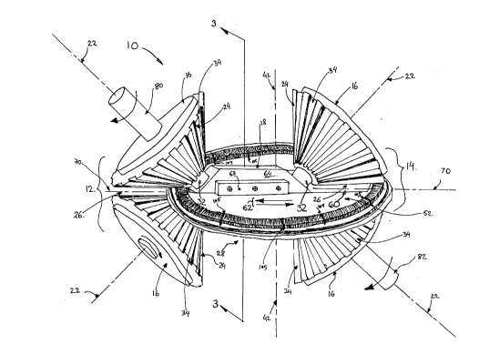
A C.V.T. according to the present invention is generally indicated by
reference 10 in Figs. 2 and 3. The C.V.T. 10 has an input gearset 12 to the leftof Fig. 2 and an output gearset 14 to the right of Fig. 2. The input and output
gearsets 12 and 14 respectively each include a pair of bevel gears 16.
Each of the bevel gears 16 is rotatably mounted at one end to a locator
10 18 described in more detail below and at the opposite end to a housing 20.
Each of the bevel gears 16 is rotatable about a respective axis of rotation 22.
The bevel gears 16 are mounted with the axes of rotation 22 generally
coplanar and with toothed bevelled faces 24 parallel and spaced apart to
define a parallel-sided opening 26 between adjacent portions of the faces 24.
15 The openings 26 are aligned to engage opposite ends of a generally disc-
shaped transfer ring 28.
The pairs of bevel gears 16 in each of the input and output gearsets 12
and 14 respectively are rotationally coupled by bevel gears 30 and may be
other than 90~ in Figure 3 which cause the bevel gears 16 of each gearset to
20 rotate at equal amounts (i.e. equal angular velocities) but in opposite
directions relative to each other.
The teeth 24 of each bevel gear 16 taper toward a narrower end 32 of
the bevel gears 16. Between each of the teeth 24 are spaces 34 which
correspond and are slightly larger in breadth than the teeth 24 so that the
25 bevel gears 16 could mesh if they were not spaced apart by the breadth of the openings 26.
The structure of the transfer ring 28 is illustrated in detail in Fig. 4.
The transfer ring 28 is of generally annular configuration and comprises a
2 ~ 86927
large number ("plurality") of adjacent segments 40 radially aligned with a
transfer ring axis 42. Each segment 40 has a generally rectangular central
portion 41 from opposite sides of which extend generally rectangular tabs 44.
The segments 40 are mounted between opposed, annular channel shaped
5 retention rings 46 with each of the tabs 44 extPn-ling into opposed channels
48 of the retention rings 46. The segments 40 are individually axially
moveable or displaceable back and forth parallel to the transfer ring axis 42
in the directions illustrated by arrows 50. The retention rings 46 act as a
guide for the segments 40. The end faces of the se~nent~ 40 extend beyond
10 the retention rings 46.
At spaced intervals, for example, every 30~ along the circumference of
the transfer ring 28, are fixed segments 105 act as constraining means to that
transfer force from the axially moveable segments 40 to the annular channel
shaped retention rings 46. The fixed segment~ 105 are rigidly secured to the
15 retention rings 46, for example by welding, and do not project above the
retention rings 46. Figure 8 illustrates this configuration in more detail.
The sides of channels 48 interact with the tabs 44 to act as first and
second stops or stop means to limit back and forth axial movement of the
segments 42 to an amount predetermined by the breadth of the channels 48
20 and the height of the tabs 44.
The transfer ring 28 is mounted between a disc shaped inner transfer
ring ret~ining member 52 which acts as a guide support structure and an
annular outer transfer ring retaining member 54. Ball bearings 56 run in
concave grooves 58 extending around the inner and outer perimeters of the
25 retention rings 46, the outer transfer ring retaining member 54 and the
inner transfer ring ret~ining member 52. The ball bearings 56 extending
"l~
'- 21 86q27 8.
around the outer perimeter of the retention rings 46 and the outer transfer
ring retAining member 52 may be ommitted. The transfer ring 28 and the
segments 40 are thereby constrained to rotate in an endless path about the
transfer ring axis 42.
The locator 18 has a generally rectangular body ext~ncling through a
generally rectangular slot 60 in the inner transfer ring retaining member 52
and is laterally moveable in the directions indicated by arrows 62 in Fig. 2.
Generally rectangular restraining members 63 secured to opposite faces 64 of
the locator 18 restrain the locator 18 from moving perpendicular to the
10 inner transfer ring retaining member 52 in the direction of the transfer ring axis 42.
Opposed faces of the rectangular slot 60 through the inner transfer
ring retention member 52 act against the faces 64 of the locator 18 to
constrain the locator 18 to movement along the rectangular slot 60. The
15 rectangular slot 60 has a slot axis 70 extending along its length. The slot axis
70, the transfer ring axis 42 and the axes of rotation 22 of the bevel gears 24
lie in the same plane.
As the input and output gearsets 12 and 14 respectively are mounted
to the locator 18, relative lateral movement between the locator 18 and the
20 inner transfer ring retention member 52 in the direction shown by arrows 62
will result in corresponding lateral movement of the transfer ring 28
relative to the bevel gears 16 along the opening 26.
Fig. 6 illustrates one manner in which relative movement between
the locator 18 and the inner transfer ring retention member may be
25 achieved. The locator 18 is rigidly secured to the housing 20. A pinion shaft90 extends through the housing 20 and is mounted so as to be constrained to
2 1 86927 9
rotate about a pinion shaft axis 92 generally coaxial with the pinion shaft 90.
A pinion 94 is rigidly mounted to one end of the pinion shaft 90 and
rotatable with the pinion shaft 90 about the pinion axis 92.
A rack 96 is rigidly mounted to the inner transfer ring retention
5 member 52 adjacent to the rectangular opening 60 and generally parallel to
the slot axis 70. The pinion 94 engages the rack 96.
The opposite end 100 of the pinion shaft 90 extends through the
housing 20 and a crank 102 extends generally radially therefrom and is
rigidly secured thereto. Rotation of the crank 102 in the direction of arrows
10 104 will cause a corresponding rotation of the pinion shaft 90 and
accordingly will rotate the pinion 94 about the pinion shaft axis 92. Rotation
of the pinion 94 will cause the rack 96 to move laterally and in turn cause
the inner transfer ring retention member 52 to move relative to the locator
18 in the direction of arrows 62.
Other means to cause relative movement between the locator 18 and
the inner transfer ring retention member would no doubt be apparent to
one skilled in the art. For example a hydraulic cylinder may be mounted
between the locator 18 and the inner transfer ring retention member 52.
Reference is now made to Fig. 5 which illustrates the
20 interrelationship between the pairs of bevel gears 16 of each of the input and
output gearsets ~12 and 14 respectively in Figs. 2 and 3) and the transfer ring
segments 40. The bevel gears 16 are arranged so that as they rotate relative to
each other in the directions shown by arrows 71, each of the teeth 24 of one
of the pairs of bevel gears 16 lines up in turn with one of the spaces 34
25 between the teeth 24 of the opposite bevel gear. In other words the adjacent
2 1 &~927 lo.
bevel gears 16 would mesh were it not for the openings 26 resulting from
the parallel spaced apart relationship of each pair of bevel gears 16.
The gap between a tip 72 of a tooth 24 of one of the bevel gears 16 and
a base 74 of the corresponding space 34 of the opposite of the bevel gears 16
generally accords with the height of the rectangular central portion 41 of the
segments 40. The depth of the spaces 34 (i.e. the height of the teeth 24)
should correspond to the predetermined amount of axial movement of the
segInents 40. Accordingly as the pair of bevel gears 16 rotate, the teeth 24 of
one of the bevel gears 16 will axially displace certain of the segments 40 in
the direction indicated by arrows 50 into the opposed space 34 thereby
causing the portion of the transfer ring 28 trapped there between to conform
to the shape of the space defined between adjacent portions of the bevel
gears 16. In a sense therefore the bevel gears 16 form temporary "teeth" in
the transfer ring 28 as the transfer ring 28 passes between them thereby
effecting a mechanical rather than a frictional transfer of force.
It will be appreciated therefore that rotation of the input gearset 12
about the axes of rotation 22 will cause the transfer ring 28 to rotate about
the transfer ring axis 42 and in turn cause rotation of the output gearset 14
about respective axes of rotation 22.
As the input and output gearsets 12 and 14 respectively include bevel
gears 16, the amount of movement imparted by the input gearset 12 on the
output gearset 14 will be determined by the position of the input and output
gearsets, 12 and 14 respectively, and the transfer ring 28.
As illustrated in Fig. 2, the transfer ring 28 runs between the narrower
end 32 of the bevel gears 16 of the input gearset 12 and the broader end of the
bevel gears 16 of the output gearset 14. This results in a gear reduction and
corresponding torque multiplication. If the input and output gearsets 12 and
14 were moved to the right as illustrated in Fig. 2 by moving the locator 18
to the right relative to the transfer ring 28, the amount of reduction would
~imini~h and as the extreme right is approached would result in a torque
5 reduction and corresponding angular velocity multiplication.
Various means of transferring rotational motion into the input
gearset 12 and out of the output gearset 14 may be used. The method
illustrated in Fig. 2 uses an input shaft 80 connected to and coaxial with one
of the bevel gears 16 of the input gearset. An output shaft 82 is connected to
10 and coaxial with one of the bevel gears 16 of the output gearset 14.
The input shaft 80 and output shaft 82 are constrained to rotate about
their respective axes of rotation 22 by bearings 84 mounted to the housing 20
and bearings 86 in the locator 18.
The rem~ining bevel gears 16 are mounted on shafts 88 extending
15 between the locator 18 and the housing 20. Bearings 115 locate the bevel
gears 16 on shafts 88 and constrain the bevel gears 16 to rotate about their
respective axes of rotation 22.
As mentioned above, the teeth 24 and spaces 34 of the bevel gears 16
are tapered in that they narrow toward the narrower end of the bevel gears
20 16. Accordingly the number of segments 40 of the transfer ring 28 trapped in
the space between opposed teeth 24 and spaces 34 would vary depending on
the breadth of the portion of the teeth 24 and spaces 34 adjacent to the
trapped segments 40.
In order for the segments 40 to lie with adjacent faces abutting the
25 segments 40 taper inwardly when viewed from above toward the transfer
ring axis 42. The tapering of the segments 40 enables the tangential load
~.
~ 2 1 86q27 12.
imparted by the input and output gearsets 12 and 14 respectively to be spread
over the entire adjacent faces of the segments 40 thereby maximizing the
robustness of the unit and minimizing wear.
It will be appreciated that one of the key elements of the present
invention is a transfer ring with movable segTnenh that acts as a continually
re-formable gear having a variable pitch. The bevel gears act as variable
diameter and pitch gears as they are moved across the transfer ring to
provide torque multiplication or reduction with a respectively associated
speed reduction or multiplication.
What has been described above is one particular embodiment of a
transfer ring and a C.V.T. utilizing such a transfer ring in association with
movable bevel gearsets. The basic components of the present invention may
however be varied considerably while staying within the scope of the
present invention. By way of example. some of the various modifications to
component structure and layout are described below.
Figure 9 illustrates a bevel gear 200 or "torque cone" having a contact
surface 202 with a cycloidal geometry. Such a geometry improves contact
between the transfer ring and the contact surface 202 by eliminating edges.
The breadth of the ridges 204 and recesses 206 which make up the contact
surface 202 vary along the length of the contact surface 202, however the
overall height or depth is kept constant across the contact surface 202. The
angle defined between the segments and a tangent to a mid-point 208
between the ridges 204 and recesses 206 should be kept smaller than 60~ to
avoid slippage. The angle is illustrated as a and referred to in the claims
below as the "mid-height contact angle".
2 1 86927 13.
A disadvantage to using a pair of bevel gears as an output gearset is
that the deformation of the transfer ring must take place under the load
imparted by the input gearset. In contrast, the deformation of the transfer
ring by the input gearset takes place in a subst~nti~lly unloaded condition.
Frictional losses and inter-segment wear may arise from the deformation of
the transfer ring under load.
It may therefore be desirable to provide an output gearset which does
not mesh with the segments of the transfer ring.
Figure 10 illustrates an alternate embodiment transfer ring 220
having a guide 222 mounted to a guide support structure 224 and
constrained by its shape and bearings 226 to move about a circular path
defined by an outer face 228 of the guide support structure. A plurality (i.e. alarge number of) relatively thin adjacent segments 229 are mounted
between inner and outer members, 230 and 232 respectively, of the guide 222
in much the same manner as illustrated in Figure 4.
Unlike the Figure 4 embodiment, there is no outer transfer ring
retaining member 54 separated from the guide by an outer race of bearings
56. In contrast, the outer guide member 232 of the Figure 10 embodiment is
provided with a ring gear 234 extending radially about it and constrained to
rotate with it. In the illustration the teeth of the ring gear 234 are formed
into the outer guide member 232 however it is conceivable that they be
separate parts.
The ring gear 234 forms part of an output gearset which may vary in
arrangement as illustrated in Figures 11, 12 and 13.
Figure 11 illustrates a C.V.T. having a gearset 250, which will herein
be described as an input gearset 250, however one should appreciate that the
2 1 86927 14.
gearset 250 may alternatively (although not as desirably) be used as an
output gearset. The input gearset 250 includes a pair of bevel gears 252
mounted with toothed faces 254 parallel and on opposite sides of a transfer
ring 220 of the type described above and illustrated in Figure 10.
Torque input is received from an input shaft 256 and transferred to
the bevel gears 252 by a pair of bevelled transfer gears 258 which are
constrained to rotate together and mesh with corresponding bevelled
transfer gears 260 extending from rear faces 262 of the bevel gears 252.
The C.V.T. of Figure 11 has an output gearset 264 which essentially
comprises a pinion gear 266 that meshes with the ring gear 234 and has a
splined hub which slidably engages a splined shaft 268. The splined shaft 268
is rotationally coupled to an intermediate shaft 270 by a first constant
velocity joint 272. A second constant velocity joint 274 connects the
intermediate shaft to an output shaft 276.
The output arrangement illustrated in Figure 11 enables the transfer
ring 220 to be moved with the input shaft 256 and output shaft 276 to have
fixed respective axes of rotation 278 and 280 while enabling the transfer ring
220 and pinion gear 266 to move relative to the bevel gears 252 in the
direction of arrows 282. It is expected that elimin~tion of a bevel gear output
gearset arrangement reduces gear forming forces on the transfer ring by
about 70 per cent.
Figures 12 and 13 illustrate output arrangements which eliminate the
constant velocity joints 272 and 274 in the Figure 11 arrangement.
Figures 12 illustrates an output gearset 284 which includes a pinion
gear 266 meshing with the ring gear 234. The pinion gear 266 is coupled to
and rotates with a first bevel gear 286. The first bevel gear 286 meshes with
",., ~l86927
~_ 15.
and rotates a second bevel gear 288. The second bevel gear 288 is coupled to
and rotates with a second pinion gear 290 about an axis 292 generally
perpendicular to an axis of rotation 294 of the pinion gear 266. The second
pinion gear 290 meshes with an is slidable along an output shaft gear 296.
The transfer ring 220, ring gear 234, pinion gear 266, first and second bevel
gears, 286 and 288 respectively, and the second pinion gear 290 are movable
in unison relative to the input gearset 250 and output shaft gear 296 in the
direction of arrows 282.
Figure 13 illustrates an embodiment similar in many respects to the
Figure 12 embodiment differing in that the output shaft 276 is driven by the
second bevel gear 288. The second bevel gear is provided with a splined hub
298 slidably engaging corresponding splines 300 on the output shaft 276. The
transfer ring 220, ring gear 234, pinion gear 266, first bevel gear 286 and
second bevel gear 288 are movable in unison relative to the input gearset
250 and splined output shaft 276 in the direction of arrows 282.
Other arrangements for the transfer ring may also be possible. Figure
14 illustrates a transfer ring 302 having guide 304 which moves in a
generally circular path about an axis 306. Segments 308 are mounted so as to
move back and forth radially relative to the axis 306.
Pigure 15 illustrates part of a C.V.T. utili~ing a transfer ring 302 as
described above with respect to Figure 14. The principle of operation is
generally the same as for the previously described C.V.T. arrangements
with the principal difference being that input gearset 310 and output gearset
312 are arranged with generally parallel opposing faces, 314 and 316
respectively, generally parallel to the axis 306 rather than radial to that axis.
16
2 1 86927
A disadvantage to the Figure 15 arrangement is that the segments 308
tend to be moved toward each other as they are moved radially inwardly
and to be moved apart as they are moved radially outwardly. Accordingly
segment shape and inter-segment spacing may be problematical. An
advantage to the Figure 15 embodiment is that the segments 308 would tend
to be hurled radially outwardly by centrifugal force. It may be possible to takeadvantage of this at high rotational speed to ~limin~te the inner bevel gear
from the input gearset 310 and output gearset 312.
In all of the above embodiments, the transfer ring has had a rigid
guide which moves about a circular path. Figures 16 and 17 illustrate a
transfer ring arrangement in which a guide 320 is made up of a plurality of
generally rectangular cassettes 322 which may either push each other in a
generally oval path or be linked or hingedly connected to pull each other
around the path. A typical hinge is shown at rerer~llce 324.
Each of the cassettes 322 has open top and bottom faces, 326 and 328
respectively, and closed side and end faces 330 and 332 respectively. Each
cassette 322 contains a plurality of adjacent segments 334. In this
arrangement the end faces 332 of the cassettes 322 act as constraining means
to cause the guide 320 to move with the segments 334.
The guide is supported on the inside by a pair of cylindrical guide
wheels 336 which comprise at least part of a guide support structure and in
the linked cassette arrangement may comprise the entire guide support
structure. If the cassettes are not linked, an outer track or guide t not
illustrated) will have to be provided. The hinge 324 may form part of the
guide support structure in arrangements where the cassettes 322 are being
pushed rather than pulled.
21 86927 17.
Figure 16 illustrates the use of paired bevel gears 338 for both the
input gearset and output gearset. Figure 17 illustrates the use of paired bevel
gears 338 for an input gearset 340. The output "gearset", which might more
properly be regarded as a sprocket includes a cylindrical toothed wheel 342
having radially extending teeth 344. The teeth 344 register and mesh with
similarly profiled recesses 346 in the inside side faces 330 of the cassettes 322.
The toothed wheel 342 is mounted on an output shaft 348 and transfers
movement from the guide 320 to the output shaft 348.
The above description is intended in an illustrative rather than a
restrictive sense. Variations to the specific structure described may be
apparent to appropriately skilled persons while remaining within the spirit
and scope of the invention as defined by the claims set out below.