Note: Descriptions are shown in the official language in which they were submitted.
CA 02186952 2002-09-11
-1- j
TESTICULAR PROSTHESIS AND METHOD OF
MANUFACTURING AND FILLING
The present invention pertains to a prosthesis, and more particularly,
relates to a testicular prosthesis having a saline filled elastomer shell
which includes a
self sealing injection site through which saline or other biologically safe
fluid is
S injected. A method of manufacturing and filling is also disclosed.
Prior art testicular prosthesis have been of solid material or have been
filled with a soft silicone elastomer or a silicone gel. See "The Why and How
of
Synthetic Replacement Testicles" by Joseph Ortenberg, M.D. and Robert G.
Kupper,
M.D. in Contemnorarv Uroloa , Oct. 1991, pp 23 - 32.
The present invention improves on the prior art devices by providing a
testicular prosthesis of a silicone elastomer having a self sealing filling
injection site
which is incorporated to provide for filling of the testicular prosthesis with
a saline
solution or other biologically safe fluid.
The art referred to and/or described above is not intended to constitute
an admission that any patent, publication or other information referred to
herein is
"prior art" with respect to this invention. In addition, this section should
not be
construed to mean that a search has been made or that no other, pertinent
information
as defined in 3? C.F.R. ~ 1.56(a) exists.
Summary of the Invention
The general purpose of the present invention is to provide a shell
member similar in size and shape to that of a testicle. Preferably, a self
sealing
injection site the subject of a co-pending application, in the name of Timothy
B.
Petrick, entitled IMPROVED SELF SEALING INJECTION SITES AND PL UGS,
IMPLANTABLE PROSTHESIS AND OTHER DEVICES UTILIZING SAME AND
METHOD OF MANUFACTURE, filed on even date herewith and assigned to the
same assignee, is secured by a suitable medical grade adhesive into one end of
the
silicone elastomer shell. The self sealing injection site is then punctured by
an
inflation device, such as a syringe and needle, to inject a solution of saline
or other
biologically safe fluid to provide a normal resilient feeling similar to that
of the
CA 02186952 2002-09-11
-2-
human testicle. Any physiologically safe solution, such as radiopaque contrast
media
or injectable saline solution may be used to fill the testicular prosthesis.
The manufacturers name and serial number may be laser engraved to
the inside of the testicular prosthesis, which is then inked or otherwise
marked and
covered with a medical grade adhesive to maintain structural integrity of the
testicular
prosthesis. Alternatively, the characters may be silk screened or other wise
appropriately applied to the elastomeric shell interior.
A novel self presenting suture tab is also incorporated to aid in straight
forward suturing where a suture tab is presented having no interfering members
which
would serve to impede the suture process. The flush but extendable tab is
provided at
the opposing end of the elastomer shell through which a suture may be attached
in
order to anchor the prosthesis in the scrotum. It does not normally extend
beyond the
profile of the prosthesis.
A method for the evacuation of air and excess saline or other
physiological solution from the interior of the testicular prosthesis, is
provided in
which stored energy forces air from an inverted evacuation domed area
outwardly
through a syringe, which is used to fill the prosthesis initially.
An assembly fixture is provided for alignment of the silicone elastomer
shell and the self sealing injection site prior to adhesive securement of the
self sealing
injection site to an opening in an end of the silicone elastomer shell.
According to an aspect of the present invention a testicular prosthesis
for implanting within a patient for the purpose of replacing a natural
testicle, the
testicular prosthesis comprises an elastomer shell having a substantially
elliptical
shape and a substantially circular cross section, the elastomer shell defining
an
interior and an exterior; a self sealing injection site connected to and
disposed on the
elastomer shell so as to communicate with both the interior and the exterior,
the
interior of the elastomer shell being substantially sealed against fluid
communication
with the exterior except for the self sealing injection site wherein the self
sealing
injection site includes an elastomer core and a filament wrapped about the
elastomer
core; and a volume of fluid contained within the interior of the elastomer
shell, such
that additional fluid may be injected into the interior of the elastomer shell
through the
self sealing injection site to increase the volume of fluid within the
interior of the
CA 02186952 2002-09-11
-2a-
elastomer shell, the volume of fluid inflating the elastomer shell to a shape
and size
conforming to the natural testicle of the patient such that the elastomer
shell and the
volume of fluid replaces the natural testicle of the patient, the volume of
fluid
remaining substantially with the elastomer shell when pressure is exerted on
the
elastomeric shell.
According to another aspect of the present invention a testicular
prosthesis for replacing a natural testicle of a patient, the testicular
prosthesis
comprises a molded elastomer shell having a generally longitudinally
elliptical shape
and a generally circular cross section, the molded elastomer shell having an
interior
substantially filled with a saline solution and a self sealing injection site
attached to
the molded elastomer shell, the self sealing injection site communicating with
the
interior of the molded elastomer shell such that a volume of the saline
solution may be
selectively injected into the interior through the self sealing injection
site, the interior
of the molded elastomer shell being substantially sealed against fluid
communication
with the exterior except for the self sealing injection site, the saline
solution inflating
the molded elastomer shell to a shape and size conforming to the natural
testicle of the
patient such that the molded elastomer shell and the saline solution replace
the natural
testical of the patient, the saline solution remaining substantially within
the molded
elastomer shell when pressure is exerted on the molded elastomeric shell,
wherein the
self sealing injection site includes an elastomer core and a filament wrapped
about the
elastomer core.
According to yet another aspect of the present invention a method for
placing an injection site into a prosthesis comprises the steps of:
providing a fixture including a cavity conforming to one end of a shell
of said prosthesis a portion on said fixture arranged to align with a bore in
the shell of
said prosthesis, and a bore extending through said fixture adapted to receive
a self
sealing injection site;
providing and placing an injection site in said bore of said fixture, said
injection site having a top surface, an elastomer core and a filament wrapped
about
the elastomer core;
placing said shell in said cavity of said fixture over said injection site;
injecting a quantity of adhesive into said shell through said injection
site with a needle;
CA 02186952 2002-09-11
-2b-
causing said adhesive to overflow the top surface of the injection site
and into and around the shell bore occupied by the injection site;
withdrawing said needle; and
rotating and tipping said fixture with said injection site and shell,
thereby forming an evacuation dome inside said shell over said injection site.
According to another aspect of the present invention, there is provided
a method for placing an injection site into a prosthesis, the prosthesis
having a shell
defining a bore extending therethrough, the injection site having a top
surface, the
method comprises the steps of providing a fixture generally conforming to a
region of
the shell of the prosthesis, the fixture defining a portion adapted to engage
the self
sealing injection site such that the self sealing injection site is generally
aligned with
the bore defined by the shell; placing the self sealing injection site in the
portion of
the fixture; placing the shell in the fixture such that at least a portion of
the top surface
of the self sealing injection site is generally aligned with the bore defined
by the shell,
and at least a portion of the self sealing injection site is received within
the bore
defined by the shell; injecting an adhesive into the shell through the self
sealing
injection site; causing the adhesive to overflow the top surface of the self
sealing
injection site around the bore; and manipulating the orientation of the shell
and the
self sealing injection site to form an evacuation dome inside the shell
disposed
proximate to and covering at least a portion of the self sealing injection
site.
According to another aspect of the present invention there is provided
a method of using a testicular prosthesis as a replacement for an absent
testicle in a
scrotum, said testicular prosthesis including an elastomeric shell defining an
interior, a
self sealing injection site, and fluid, wherein:
the elastomeric sheet of the testicular prosthesis is provided with the self
sealing injection site being operatively connected to the elastomeric shell
such that the
self sealing injection site is in communication with the interior of the
elastomeric shell;
and
wherein at least a portion of the interior of the elastomeric shell is filled
with the fluid through the self -sealing injection site.
According to yet another aspect of the present invention there is
provided a method of using of a testicular prosthesis as a replacement for an
absent
CA 02186952 2002-09-11
-2c-
testicle in a scrotum, said testicular prosthesis including a self sealing
elastomeric shell
defining an interior, an injection site, and fluid, wherein:
the elastomeric shell of the testicular prosthesis is provided with the self
sealing injection site being operatively connected to the elastomeric shell
such that the
self sealing injection site is in communication with the interior of the
elastomeric shell;
and
wherein said testicular prosthesis is used in a scrotum;
at least a portion of the fluid is injected into the interior of the
elastomeric
shell through the self sealing injection site, said portion of the fluid
injected into the
interior of the elastomeric shell either inflating the testicular prosthesis
to a
predetermined size corresponding approximately to the size of the absent
testicle or
replacing a quantity of the fluid that has migrated through the elastomeric
shell into the
scrotum or both.
According to another aspect of the present invention there is provided
1 S a method for filling a prosthesis having an elastomeric shell and a self
sealing inj ection
site with a fluid using an injection needle having at least one opening, said
elastomeric
shell defining an interior and a self sealing site including an elastorner
core and a
filament wrapped about the elastomer core, said method comprising the steps of
inserting the injection needle through the self seating injection site,
injecting a sufficient quantity of the fluid through the injection needle
and the self sealing injection site to provide excess fluid within the
interior of the elasto-
meric shell so as to expand the elastomeric shell and compress air disposed
within the
interior;
orienting the prosthesis such that the self sealing injection site is disposed
so as to allow air within the interior of the elastomeric shell to collect in
the proximity of
the self sealing injection site; and
withdrawing the air from within the interior of the elastomeric shell
through injection needle having the opening aligned proximate to the injection
site.
According to yet another aspect of the present invention, there is
provided a method for filling an interior of a flexible, inflatable shell of a
prosthesis
with a fluid using an injection device having at least one opening wherein the
prosthesis comprises an injection site that includes an elastomer core and a
filament
wrapped about the elastomer, said method comprising the steps of:
CA 02186952 2002-09-11
-2d-
inserting the injection device through the injection site into the interior
of the flexible, inflatable shell for filling the interior with the fluid;
injecting the fluid into the interior of the shell;
orienting the prosthesis such that air accumulates at a selected region
of the interior of the shell;
positioning the opening of the injection device relative to the selected
region of the interior of the shell where air has accumulated such that the
opening of
the injection device is disposed within the selected region; and
withdrawing the air through the opening of the injection device to
purge the air from the interior of the flexible, inflatable shell of the
prosthesis.
According to another aspect of the present invention, there is provided
a method for placing indicia onto a prosthesis having an injection site
comprising an
elastomer core and a filament wrapped about the elastomer core and having an
elastomer shell defining an interior and an interior surface, said elastomer
shell having
an opening extending through said elastomer shell communicating with said
interior,
said interior being substantially enclosed by said elastomer shell apart from
said
opening, said method comprising the steps of
turning the elastomer shell of the prosthesis inside out such that the
interior surface is exposed;
placing the indicia onto a predetermined area of the interior surface of
the elastomer shell;
marking the indicia so as to be visible when the elastomer shell is
subsequently reinverted; and
re-inverting the elastomer shell such that the indicia and the interior
surface are disposed within the interior of the elastomer shell and the
indicia is visible
exterior to the prosthesis.
According to yet another aspect of the present invention, there is
provided a method for placing indicia on an interior surface of a shell of a
prosthesis
using an inverting tool, said shell defining an interior, an interior surface
on which
said indicia is placed, an exterior surface, and an opening communicating with
said
interior, said prosthesis having an injection site comprising an elastomer
core, a
filament wrapped about the elastomer core, and a tab disposed on said exterior
surface
CA 02186952 2002-09-11
-2e-
of said shell, said inverting tool having a portion shaped to engage said tab,
said
method comprising the steps of
engaging the tab with the portion of the inverting tool shaped to engage
the tab;
inverting the shell by pressing the portion of the inverting tool and the
tab through the opening of the shell to expose the interior surface of the
shell;
marking the indicia on the interior surface of the shell; and
reinverting the shell through the opening of the shell so that the indicia
is within the interior of the shell.
_3 ~695~
Brief Description of the Figures
Other objects of the present invention and many attendant advantages
thereof be readily appreciated as the same becomes better understood by
reference to
the following detailed description, when considered in connection with the
accompanying; drawings, in which like reference numerals designate like parts
throughout the Figures thereof and wherein:
Figure 1 illustrates a perspective view of a testicular prosthesis of the
present invention;
Figure 2 illustrates a cross-sectional view along line 2-2 of Figure 1;
Figure 3 illustrates an end view (upper end in Figure 2) of the testicular
prosthesis showing the suture site;
Figure 4 illustrates a cross-sectional view along line 4-4 of Figure Z;
Figure S is a perspective view of a preferred injection site of the filament
wrapped type as more fully described in the aforementioned co-pending
application.
Figure 6 illustrates a greatly enlarged cross-sectional view along line S-5
1S of Figure S;
Figure 7 illustrates an alignment fixture;
Figure 8 illustrates the method~of injecting adhesive into the interior of
the elastomeric shell of the prosthesis when mounting an injection site
therein;
Figure 9 illustrates the elastomeric shell of the prosthesis being rotated
off vertical to form an evacuation dome;
Figure 10 illustrates ~ the elastomeric shell of the prosthesis and self-
sealing injection site subsequent to fixture removal;
Figure 11A illustrates complete encapsulation of the self-sealing injection
site within the, cylindrical bore of the elastomeric shell of the prosthesis;
Figure 11B illustrates radiopaque encapsulation of the self-sealing
injection site in a testicular prosthesis;
Figure 11C illustrates radiopaque encapsulation of the self-sealing
injection site in a testicular prosthesis;
2Ig6~52
-4- ~ ~ 6 9 '~ ~
Figure 12 illustrates the serialization and identification area of the
testicular prosthesis;
Figure 13A illustrates a front view of an inverting tool used for inverting
or turning a prosthesis inside out;
Figure 13B illustrates a side view of an inverting tool;
Figure 14 illustrates the head of the inverting tool of Figures 12A and
12B connected to the dimple and suture tab of an empty prosthesis;
Figure 15 illustrates depressing of the empty prosthesis by the inverting
tool;
Figure 16 illustrates passage of the prosthesis shell wall tluough its
cylindrical bore for inverting the prosthesis;
Figure 17 illustrates a fully inverted elastomeric prosthesis shell;
Figure 18 illustrates the elastomeric prosthesis shell of Figure 16 reversed
for laser engraving with the inserting tool removed;
Figure 19 illustrates a side view of a re-inverting tool for returning the
prosthesis to its original condition as shown in Figure 13;
Figure 20 illustrates engagement of the re-inverting tool with the
elastomeric shell of the prosthesis;
Figure 21 illustrates the suture tab being presented for suturing by
squeezing the prosthesis;
Figure 22 illustrates the filling of the testicular prosthesis with fluid
Figure 23 illustrates the evacuation of air and excess solution from the
testicular prosthesis, and
Figure 24 illustrates a butterfly needle penetrating the evacuation dome
of the testicular prosthesis.
Detailed Description of the Preferred Embodiments
Figure 1 illustrates a perspective view of the testicular prosthesis 10
including a shell 12 which is transfer, injection, compression or otherwise
suitably
molded from a silicone elastomer such as Dow Corning Q7-4840 or Q7-4735 or an
equivalent material, such as NUSIL TECHNOLOGY MED-4735 OR MED 4840. The
elastomeric shell 12 is elliptical in longitudinal cross-section to replicate
the shape of
a testicle and is of a circular shape in transverse cross section. The shell
12 can be
2186952
-5-
produced in a number of sizes to accommodate the proper testicle size required
by a
patient, and can be filled as required to a preferred firmness or feel. The
elastomeric
shell wall is approximately .030 inches thick on the sides 14 for purposes of
example
and illustration only, and increasingly tapers to a thickness of 0.170 inches
at one end
16 to accommodate a self-sealing injection site 18. Molding with matched
cavity and
core tooling is the preferred mode of fabrication due to the varying wall
thickness of
the shell. Dip molding may be used although it is not as precise or as fast.
The self-
sealing injection site 18 is bonded into an opening 24 in the end 16 of the
elastomeric
shell 12 by a medical grade adhesive 20 and aligned therein prior to bonding
by means
of a fixture as described later in detail. A self presenting suture tab 22 is
carried at the
opposite end of shell 12 for suturing the shell to the scrotum or other
convenient
attachment point, if desired.
Figure 2 illustrates a crass-section of the testicular prosthesis 10 along
line 2-2 of Figure 1. All numerals correspond to those elements previously
described.
Shell 12 includes an outer surface 15 and an inner surface 26. The thick wall
end 16
of elastomeric shell 12 includes the cylindrical bore 24 into which the self-
sealing
injection site 18, the preferred form of which is the subject of the
aforementioned co-
pending patent application, is centrally aligned and bonded by a medical grade
adhesive
20. Adhesive 20 also bonds to the inner surface 26 of the shell wall 14 over
an area
thereof as shown in Figure 12, as well as in the cylindrical bore 24 and to
all external
sides of the self sealing injection site 18. An evacuation dome 25 is located
above the
inner end of self-sealing injection site 18. A dimple 28 at the opposing end
30 of
elastomeric shell 12 serves as a shock absorptive mount connecting the
relatively thin
wall 14 to the suture tab 22 through which a suture may be passed. It is noted
that the
profile of suture tab 22 conforms generally to the elliptical profile of shell
12 so as not
to exceed the de~: ice profile. The suture tab 22 may contain a hole 23 which
is
preferably oval in shape. Alternately, a suture, with or without a needle, may
be pre-
attached. A serialization and identification area 64 may also be included on
inner
surface 26 and is preferably covered by the medical grade adhesive 20, as
described
later in detail.
Figure 3 is an end view of end 30 of the testicular prosthesis 10 showing
the tab 22 from the top. All numerals correspond to those elements previously
described.
-6-
Figure 4 is a cross-sectional view along line 4-4 of Figure 2. Illustrated
in particular is substantially equidistant annular space 54 between self-
sealing injection
site 18 and cylindrical bore 24 which contains adhesive 20. The self sealing
injection
site 18 includes a center elastomeric core 32 bonded by a continuously
adhesive coated
S strand 34 as described in Figure 5 in more detail. All other numerals
correspond to
those elements previously described.
Figure 6 is a cross-sectional view of the self-sealing injection site 18
along line 6-6 of Figure 5. The injection site shown in Figure 5 is the type
referred to
in the aforementioned co-pending application. All numerals correspond to those
elements previously described. The center core 32 of self-sealing injection
site 18 of
these Figures 5 and 6 is a silicone elastomer which in fabrication is
stretched and then
tightly bound while in compression by an adhesive coated fiberglass strand 34
having
a plurality of filaments 35a-35n. This procedure holds the center core 32 in
compression thereby storing energy in the core and enhancing the self-
sealability of the
self-sealing injection site 18. This is more fully described in the
aforementioned co-
pending application. A medical grade flexible adhesive 37, such as silicone
adhesive
Raumedic Medical Grade Adhesive (SI 1511), adheres strands 34 to themselves
and to
core 32. Variations in construction of preferred injection site 18 are
described in the
aforementioned co-pending application.
Figure 7 illustrates a fixture 36 used for alignment of the self-sealing
injection site 18 concentrically with the cylindrical bore 24 of thick end 16
of
elastomeric shell 12. All numerals correspond to those elements previously
described.
Fixture 36 may be made of plastic and includes generally a number of radiused
portions
including an upper radiused body portion 38 and a lower radiused body portion
40. A
cavity 42 conforming to the outer configuration of thick end 16 of elastomeric
shell 12
aligns centrally in the upper radiused body portion 38 for subsequent
alignment with the
same as shown in Figure 8. Another radiused portion 44 extends upwardly into
the
region of cavity 42 to closely align within the cylindrical bore 24 of the
elastomeric
shell thick end 16 as shown in Figure 8. Three bores 46, 48 and 50 align
axially either
partially or fully in the radiused portion 44, the upper radiused. body
portion 38 or the
lower radiused portion 40 as illustrated. Bore 46 accommodates self-sealing
injection
site 18 and bores 48 and 50 accommodate a fill needle 52 as illustrated in
Figure 8.
~~~~~~3~
Figure 8 demonstrates the method of injecting medical grade adhesive 20
into the interior 80 of elastomeric shell 12 to bond injection site 18 into
opening 24.
All numerals correspond to those elements previously described. Elastomeric
shell 12
is first aligned in the conforming shaped cavity 42 of fixture 36. The
radiused portion
S 44 of fixture 36 aligns centrally within the cylindrical bore 24 of
elastomeric shell 12.
The self-sealing injection site 18, which is placed in the upper bore 46 prior
to
alignment of the elastomeric shell 12 with the fixture 36, is also centrally
aligned within
the cylindrical bore 24. When alignment has been accomplished, a non-coring
needle
52 having one or more ports 53 and having a source of thinned medical grade
adhesive
20 attached thereto (not shown) is inserted through the bores 50 and 48 and
through the
self-sealing injection site 18. Adhesive 20 then enters the lower region of
the
elastomeric shell 12 about and above the vicinity of bore 24 as illustrated
such that
adhesive 20 covers the lower inner region of elastomeric shell 12, the
serialization and
identification area 64, and the top inner surface of self sealing injection
site 18. Needle
52 is then withdrawn from injection site 18 and fixture 36. The elastomeric
shell 12
and fixture 36 are then slowly rotated (shown in Figure 9) and are
progressively tipped
from the vertical during rotation to allow adhesive 20 to puddle in an annular
fashion
around the inner center portion of end 16 to form evacuation dome 25 as
illustrated in
Figure 9. The adhesive is then allowed to cure after formation of evacuation
dome 25.
After curing, fixture 36 is withdrawn from engagement with the elastomeric
shell 12
leaving self-sealing injection site 18 concentrically aligned within
cylindrical bore 24
and adhered to the lower region of elastomeric shell 12 by the interceding
medical
grade adhesive 20 as shown in Figure 10.
Figure 9 illustrates the elastomeric shell 12 being rotated about an axis
58 which is at a variable angle 60 to the vertical 62: Angle 60 generally is
35 °, but
can include a range of degrees in that several factors . such as but not
limited to
elastomeric shell 12 size; adhesive viscosity, rate of rotation, angle of
rotation,
temperature, and adhesive setting time may require different angular settings,
different
rotation speeds, as well as different rates of tipping, other than described
herein. A
suitable rotatable clamping device 63 slowly rotates the fixture 36 and the
adhesive
laden elastomeric shell 12 at a speed of 4 rpm plus or minus one rpm, for
example.
The viscous adhesive 20 flows outwardly leaving the shaped evacuation dome 25
centered radially about the longitudinal axis of elastomeric shell 12 when
shell 12 is
~.1~~9 ~~
_8_
tipped at an angle as now described in detail. The axis of rotation 58 is
progressively
and slowly tipped over a period of about one minute from the vertical axis 62
until
reaching the desired angle 60 of 35° which is the most desirable of
angles which can
range from 35 to 55 degrees depending on the size of elastomeric shell 12 and
the other
factors previously described. During this slow tipping and rotation, adhesive
20 flows
from the area over and about the upper area of self sealing injection site 18
and along
the lower portion of inner surface 26 to remove adhesive 20 from the area
overlying
self sealing injection site 18 to form the evacuation dome 25. Alternatively,
the
elastomeric shell 12 may be spun rapidly from S00 to 1,000 rpm for 10 to 20
seconds,
for purpose of example, along the vertical axis to cause the adhesive 20 to
flow away
from the center to form evacuation dome 25.
Figure 10 shows the elastomeric shell 12 and the self-sealing injection
site 18 subsequent to removal of fixture 36. Again, all numerals correspond to
those
elements previously described. The self sealing injection site 18 is suspended
concentrically from the adhesive 20 within cylindrical bore 24. An annular
space 54
defined by the annular area between the circumferential surface of the self
sealing
injection site 18 and the adjacent walls of the cylindrical bore 24 and
another circular
space area 56 between the plane of the outer surface of the self sealing
injection site 18,
the bottom of the annular space 54 and a plane across the outer opening of the
cylindrical bore 24 are then back-filled by the medical grade adhesive 20 as
illustrated
in Figure 11A to fully and adhesively secure and encapsulate the self sealing
injection
site 18 within cylindrical bore 24 of elastomeric shell 12.
Figure 11A illustrates the complete encapsulation of the self sealing
injection site 18 within cylindrical bore 24 of elastomeric shell 12. Again,
all numerals
correspond to those elements previously described. Backfilling with adhesive
20 of the
cylindrical bore 24 in areas 54 and 56 forms a homogenous surroundment of
adhesive
20 about the self sealing injection site 18. The newly applied backfill
adhesive, being
of the same type, provides for bonding of the previously cured adhesive and
the newly
applied adhesive to form a homogenous bonding.
Elastomeric shell 12 is of a medical grade low durometer silicone
elastomer, tlws allowing the elastomeric shell 12 to be soft and resilient.
The self-
sealing injection site 18 is also preferably constructed of a low durometer
medical grade
silicone elastomer which has minimal palpability and which is easily
compressed. The
zigs95z
-9-
silicone adhesive 20 when cured and hardened preferably has durometer and
elongation
qualities similar to the other silicone elastomeric members which it bonds
together. The
silicone adhesive 20 being medical grade is biocompatable and biostable.
Although a
compressed self sealing injection site 18 is incorporated, other suitable
valves, such as
a diaphragm valve or leaf valve may be used for shell filling. The elastomeric
shell
may also be dip molded on a mandrel.
Also illustrated in this Figure 11A is an annular area 64 for serialization
and identification of the product. A laser cuts or engraves identification
indicia and a
serial number within the annular area 64. The laser cuts or engravings are
filled with
an elastomer containing a dye such as, but not limited to, carbon black to
accent the
identification indicia and serialization.
The laser engraving, of course, occurs before the medical grade adhesive
is applied to the surface 26 for the adhering of the self-sealing injection
site 18
within cylindrical bore 24. The accessing of the interior of the elastomeric
shell 12 for
15 this purpose is described with reference to Figures 13-20. During the
process of
adhering the self-sealing injection site 18 to the elastomeric shell 12,
adhesive 20 flows
along and adjacent to the thicker portion 16 and covers, fills in and mends
the laser cuts
in the annular area 64 to restore and maintain structural integrity, as well
as sealing the
accenting carbon black or other material from the interior of elastomeric
shell 12. The
20 serialization and identification are viewed through the clear elastomeric
shell 12 in the
area of the thicker portion 16 as depicted in Figure 12. .
Alternatively, the serialization. and identification indicia may be silk
screened or otherwise suitably adhered or applied to the annular area 64 or
any other
suitable portion of the inner surface 26.
Figure 11B illustrates the complete encapsulation of self-sealing injection
site 18 and also the incorporation of a band of suitable radiopaque adhesive
20a
containing for example barium sulfate (BaSo4) in a range of 14% to provide a
radiopaque member surrounding the self-sealing injection site 18 in the upper
portion
of the annular area of the cylindrical bore 24 surrounding the self-sealing
injection site
18. Band 20a is placed in position and then adhesive 20 is backfilled into the
remaining
area of cylindrical bore 24 about the remaining portion of the self-sealing
injection site
18 as before described and in direct adhesion with the barium sulfate laden
adhesive
20a. All numerals correspond to those elements previously described.
-10-
Figure 11C illustrates the complete encapsulation of a self-sealing
injection site 18 incorporating an alternate band arrangement of suitable
radiopaque
adhesive 20b containing barium sulfate (BaSo4) in a range of 14% to provide
for a
radiopaque member surrounding the self-sealing injection site 18. Adhesive 20b
is
backfilled in areas 54 and 56 of cylindrical bore 24 in direct contact with
adhesive 20
to complete the encapsulation of self-sealing injection site 18. All elements
correspond
to those elements previously described.
Figure 12 is a top view of the testicular prosthesis 10 showing the
serialization and identification area 64 as visible through the thick end 16
of elastomeric
shell 12 as previously mentioned. All numerals correspond to those elements
previously
described.
Figures 13A and 13B illustrate a front view and a side view,
respectively, of an inverting tool 66 having a handle 68, an essentially
rounded head
70 and a groove 72 aligned across and through head 70.
Figure 14-17 illustrate the method of inverting elastomeric shell 12 (prior
to placement of injection site 18) for exposing inner surface 26 and the laser
cutting of
the serialization and identification area 64 on the interior surface 26 when
elastomeric
shell 12 has been temporarily turned inside out, thus causing the inner
surface 26 to
become-a temporary "outer surface". All other numerals correspond to those
elements
previously described. The inverting process starts with the positioning of
elastomeric
shell 12 to place cylindrical bore 24 in the top most position as shown in
Figure 14.
The inside surface 26 is wetted with water and then drained. A small amount of
lubricant 74 such as alcohol is then placed in the elastomeric shell through
the
cylindrical bore 24 and allowed to drain downwardly and around and about the
inner
surface of the dimple 28.
As illustrated in Figure 14, head 70 of inverting tool 66 is placed in
intimate contact with dimple 28, and the groove 72 of the tool is brought into
intimate
contact with the suture tab 22. The alcohol or other lubricant 74 facilitates
turning the
elastomeric shell 12 inside out. Preferably the upper portion of elastomeric
shell 12
and the inverting tool 66 are exchanged vertically such that inverting tool 66
is
positioned downwardly with respect to elastomeric shell 12 as illustrated in
Figure 15.
The inside surface 26 in the vicinity of the lubricant wetted dimple 28 is
then pushed
through cylindrical bore 24 as illustrated in Figure 16. Figure 16 illustrates
the
-11-
engagement and passage of the shell wall 14 tluough cylindrical bore 24. It is
noted
that the inner surface 26 at this stage is transitioning from an inner surface
to an "outer
surface", and the outer surface 15 is transitioning to an "inner surface", all
temporarily
for the placement of the indicia and the like.
Figure 17 illustrates the fully inverted elastomeric shell 12 having at this
stage been completely reversed to fully transpose interior surface 26 to an
"outer
surface" and ready the elastomeric shell for laser serialization and
identification. The
inverting tool is then removed and elastomeric shell 12 rinsed with deionized
water and
oven dried at 130°F until dry.
Figure 18 illustrates a method of laser cutting the indicia and
serialization. All numerals correspond to those elements previously described.
Elastomeric shell 12 having been turned inside out as previously described,
thus
positioning the former inner surface 26 to the exterior. The annular
identification and
indicia area 64 is fully exposed so that a laser beam 76 from a laser gun 78
may scribe
identification and serialization indicia into the annular area 64. A thin coat
of liquid
colored silicone elastomer is then applied over the laser engraved areas using
a sponge
tipped or other suitable applicator. The excess silicone elastomer is removed
with a
swab and Freon or other suitable solvent. The inked elastomeric shell 12 is
then cured
at 200°F +/- 5°F for a suitable length of time.
Figure 19 illustrates a side view of a re-inverting tool 80 including a
handle 82, a truncated cone-like tip 84 and a conical recess 86 in the tip 84.
Figure 20 illustrates the engagement of re-inverting tool 80 with the
inverted elastomeric shell 12. All numerals correspond to those elements
previously
described. The re-inverting process is quite similar to the inverting process.
Surface
15, now which is presently the "inner surface", is wetted with water and
trained. A
small amount of lubricant is then introduced for facilitating the re-inverting
of
elastomeric shell 12. Recess 86 of the re-investing tool is brought into
contact with
reversed dimple 28 as shown in Figure 20. Elastomeric shell 12 and re-
inverting tool
80 are vertically reversed to allow the lubricant to flow about surface 15.
The re-
inverting tool is then pushed to extrude the dimple 28 and' shell wall 14
through
cylindrical bore 24 to completely re-invert the elastomeric shell 12. The re-
inverted
elastomeric shell is washed and dried and is then ready for further processing
as already
described above having to do with placement of the injection site and so
forth:
2I~69~2
-12-
Figure 21 illustrates the suture tab 22 being presented by grasping and
squeezing the upper portion of the testicular prosthesis 10 between a thumb 88
and a
finger 90. All other numerals correspond to those elements previously
described. This
action causes reversal and outward distention of dimple 28 to elevate the
suture tab 22
above the elliptical profile curve of elastomeric shell 12, thus presenting a
suture tab
22 having unrestricted access. The distension of the suture tab 22 provides
clearance
for suture needle introduction. This procedure allows suturing with reduced
possibilities of puncture of elastomeric shell 12 as suture tab 22 is
presented
unencumbered by interfering and adjacent surfaces. Flexing of the shell
presents the
suture tab for easy suture needle access to reduce puncture vulnerability.
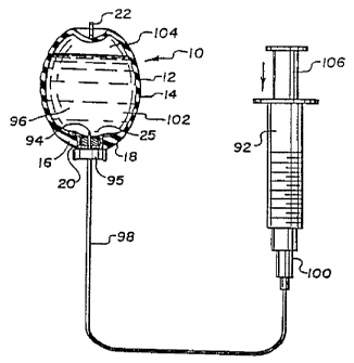
Figures 22 and 23 illustrate the steps for the preferred method of filling
the testicular prosthesis 10 with a saline or other biologically safe fluid.
All numerals
correspond to those elements previously described. A purged syringe 92 having
a non-
coring butterfly needle 94 is used to inject and overfill an amount of saline
or other
suitable solution 96 into the interior of the testicular prosthesis 10 via an
infusion line
98, the non-coring butterfly needle 94 and Luer fitting 100. The butterfly
needle 94
also includes a planar handle 95 which serves as a stop device to allow
penetration of
the needle 94 to a predetermined depth as described later in detail. The non-
coring
butterfly needle 94 is inserted through the medical grade adhesive 20, through
the self-
sealing injection site 18 and just beyond the evacuation dome 25 into the
interior 102.
Preferably prosthesis 10 is maintained upright as shown in the Figure during
filling but
this is not necessary. The syringe plunger is slowly depressed to distend
(indicated by
the arrows) the testicular prosthesis 10 to about ~1 to 1 1/2 times its empty
size.
Solution 96 forcibly enters the interior 102 and causes several actions.
Firstly, air 104
in the elastomeric shell 12 is compressed by the incoming solution 96.
Secondly, the
wall 14 of the elastomeric wall is expanded outwardly due to the action of the
incoming
solution 96 and the compression of the air 104. Stored energy caused by these
actions
is later used to evacuate the air 104 from the interior 102 as described with
reference
to Figure 23. More solution 96 is injected into the interior 102 than is
normally
required. Any excess solution can be drained off during the evacuation process
to give
the right "feel" to the testicular prosthesis 10. It is important to note that
the butterfly
needle 94 is of a non-coring type where the ports are included in the side
wall of the
needle to avoid any material being cored out or loosened by a needle. Cores
could
~18695~
-13-
cause possible clogging during the air evacuation process as now described
with
reference to Figure 23.
Figure 23 illustrates the air evacuation portion of the filling method. All
numerals correspond to those elements previously described. The filled
testicular
prosthesis 10 is inverted causing the contained air 104 to migrate from near
the suture
end to the end nearest the evacuation dome 25, which is adjacent to the now
upwardly
positioned self-sealing injection site 18. The testicular prosthesis 10 is
gently shaken
until all internal air 104 is one large bubble in the upper end. Once this is
accomplished, the plunger 106 of syringe 92 is progressively withdrawn. The
stored
energy in the testicular prosthesis 10 causes the compressed air 104 to exit
through the
ports) of the butterfly needle 94 as the plunger 106 is manually released and
the air
travels to the top of syringe 92. Walls 14 which were outwardly and forcibly
expanded
during the first portion of the filling process, now relax inwardly (indicated
by arrows)
to assist in expelling of any remaining air 104. As this occurs, the level of
solution 96
approaches evacuation dome 25. Air 104 is concentrated at this point in the
procedure
substantially to the area of the evacuation dome 25 where the air and any
desired
amount of excess solution 96 is subsequently drawn off through butterfly
needle 94.
When air 104 is expelled and when the desired inflation by solution 96 of the
testicular
prosthesis 10 is reached, butterfly needle 94 is withdrawn and the self-
sealing injection
site 18 seals the puncture caused by the butterfly needle 94, thus sealing the
interior 102
of the testicular prosthesis 10. The self sealing injection site 18 can be
punctured
repeatedly permitting adjustment of the fluid volume if desired.
Figure 24 shows the butterfly needle 94 penetrating the evacuation dome
25. All numerals correspond to those elements previously described. Handle 95
acts
as a stop and is located at a predetermined point along needle 94 allowing the
orifices)
108 to be precisely located at the same level and coinciding with the upper
most portion
of the evacuation dome 25. The preferred placement of the orifices) 108 is as
illustrated, where the orifices) 108 straddle the evacuation dome area 25a,
which is the
upper most central area of the evacuation dome 25 when the testicular
prosthesis 10 is
positioned for removal of air 104 and some of solution 96. This coinciding
orifice-to-
dome relationship insures withdrawal of some solution, and more importantly,
of air
104 from the uppermost portion of the interior 102. The use of the handle 95
as a stop
prevents the butterfly needle 94 from extending too far into the interior 102
which
-14-
would allow only removal of air 104 or solution 96 up to the level of the
orifices) 108.
This could be lower than that of the evacuation dome surface 25a if not
properly
placed. The use of handle 95 also insures that butterfly needle 94 will not be
inserted
to an insufficient depth whereby the orifices) 108 are buried in the residing
self-sealing
injection site 18, thus restricting outward flow from the interior 102 of the
testicular
prosthesis 10.
Various modifications may be made to the present invention without
departing from the apparent scope of the following claims.
While this invention may be embodied in many different forms, there are
described in detail herein specific preferred embodiments of the invention.
This
description is an exemplification of the principles of the invention and is
not intended
to limit the invention to the particular embodiments illustrated.
The filling method has been described as being accomplished
preoperatively i.e., immediately before implantation or at the time of
manufacture as
a prefill. However, it may be readily accomplished postoperatively i.e., after
implantation as well.