Note: Descriptions are shown in the official language in which they were submitted.
CA 02187285 1999-06-17
WO 96/7793 ~ ' PCT/US96/02780
-1-
APPARATUS/METHOD FOR ELECTROCHEMICALLY MODIFYING
CHROMATOGRAPHIC: MATERIAL
FIELD OF THE INVENTION
This invention rf:lates to chromatography columns, apparatuses, and
methods. In particular, the columns of the present invention can be used as
the separation column in electroelution chromatography and are also adaptable
for use as a self=regenerating suppressor in suppressed ion chromatography.
The columns of the present invention may also be used to separate a wide
range of compounds on both an analytical and preparative scale.
20
30
WO 96/27793 , PCTIUS96102780
~ .
2 2187285
BACKGROUND OF THE INVENTION
A. Sinele Column Ion C romatoe_ran_hv
Single Column Ion Chromatography (SCIC) is a method of ion analysis
in which ions are separated in an ion exchange column (e.g., separator
column) and subsequently measured by a conductivity detector connected
directly to the separator column. In SCIC, special ion exchange resins of low
capacity, and eluants with either much higher or much lower equivalent
conductance than the ions being measured must be employed. In ion
chromatography, sample ions generate a signal at a conductivity detector. The
signal is proportional to the sample ion concentration and is the difference
in
equivalent conductance between the sample ion and the eluant ion. SCIC
sensitivity is limited by the difference in equivalent conductance between the
sample ions and the eluant ions. This sensitivity is adequate and even
preferred for some sample types, especially for cationic samples, where the
difference in equivalent conductance between the sample and eluant ions is
very large. However, for many other samples, particularly anionic samples,
where the difference in equivalent conductance between the sample ions and
eluant ions is small, sensitivity can be greatly increased by a second and
preferred type of ion analysis called chemically suppressed ion chromatography
(SIC).
B. SupQressed Ion Chromatogra~v ( I .l
Suppressed ion chromatography (SIC) is a form of commonly practiced
ion analysis characterized by the use of two ion-exchange columns in series
followed by a flow through conductivity detector. The first column, called the
separation column, separates the ions of an injected sample by elution of the
sample through the column using an electrolyte as an eluant, i.e., usually
dilute
base or acid in deionized water. The second column, called the "suppressor"
or "stripper", serves two purposes. First, it lowers the background
conductance of the eluant to reduce noise. Second, it enhances the overall
conductance of the sample ions. The combination of these two factors
significantly enhances the signal to noise ratio, thus increasing sensitivity.
This technique is described in more detail in U.S. Pat. Nos. 3,897,213,
3,920,397, 3,925,019 and 3,926,559. In addition, suitable ion exchange
packings for the separation column are described in detail in U.S. Pat. Nos.
3,966,596, 4,101,460 and 4,119,580. A detailed description of ion
CA 02187285 1999-06-17
WO 96127793 . PCT/US96/02780
-3-
chromatography :is additionally provided in Small et al., "Proceedings of an
International Conference on the Theory and Practice of Ion Exchange,"
University of Cambridge, U.K., July, 1976; and also, Small et al., "Novel Ion
Exchange Chromatographic Method Using Conductimetric Detection",
Analytical Chemistry, Vol. 47, No. 11, September 1975, pp. 1801 et seq.
C. Gradient >=;lution T'echnologv
To separate or elute sample ions retained on an ion-exchange column,
an eluant containing co-io:ns of the same charge of the sample ions is routed
through the separation column. The sample co-ions in the eluant partially
displace the sample ions on the ion-exchange column, which cause the
displaced sample ions to flow down the column along with the eluant.
Typically, a dilute: acid or base solution in deionized water is used as the
eluant. The eluant is typically prepared in advance and routed through the
column by either gravity c~r a pump.
Rather than using a. homogenous eluant throughout the separation
process, it is someaimes ac(vantageous to use a gradient eluant, i.e., an,
eluamt
wherein the concentration ~of one or more components changes with time.
Typically, the eluant starts at a weak eluting strength (e.g. a low
concentration
of the sample co-ions) and gets stronger (e.g. a higher concentration of the
sample co-ions) during the separation process. In this way, easily eluted ions
are separated during the weaker portion of the gradient, and ions that are
more
difficult to elute a.re separated during the stronger portion of the gradient.
The
eluant concentration changca during the gradient and suppressing or balancing
the concurrent chaJ~ge in background conductance is required so the sample
signal may be discriminated from the background signal. An example of such
gradient elution techniques are disclosed in U.S. Pat. Nos. 4,751,189 and
', 5,132,018.
While the above patents utilize solutions prepared in advance to form a
gradient eluant, U.S. Pat. No. 5,045,204 to Dasgupta et al. uses
electrochemical methods to generate a high purity eluant stream that may flow
directly to the separation column as it is produced, and which may be
generated as a gradient. In the Dasgupta patent, a product channel is defined
by two permselective membranes and is fed by a source of purified water.
WO 96/27793 218 7 2 8 5 PCTIUS96102780
_4_
One of the permselective membranes only allows the passage of negatively
charged hydroxide ions, which are generated on the side of this membrane
opposite the product channel by the electrolysis of water at a cathode. The
hydroxide ions are driven by an electric field through the membrane into the
product channel in an amount corresponding to the strength of the electric
field. The other permselective membrane only allows the passage of positively
charged ions. On the side of this membrane opposite the product channel there
is a source channel, which is continuously fed with a NaOH solution and in
which an anode is positioned. The Na+ ions are driven by the electric field
through the membrane into the product channel in an amount corresponding to
the strength of the electric field. By this process, a high purity sodium
hydroxide (NaOH) solution is produced. This solution may be used as the
eluant for a chromatography column, and the concentration of this eluant may
be varied during the chromatographic separation by varying the strength of-the
electric field, thereby generating a gradient eluant.
The foregoing methods of elution ion chromatography suffer from
certain disadvantages, however. Among these disadvantages is that an outside
source of eluant or eluant counter-ions is required. Also, after eluting the
sample ions from the chromatography column, all of these eluants require
suppression in order to provide an accurate quantitative analysis of the
sample
ions. Finally, in general practice, all of the above methods of eluting are
only
applicable to one of either cation or anion sample ions within a single sample
run. If one wishes to analyze both the cations and anions from a single
sample, two chromatographic separations must be performed using either two
apparatuses and two distinct eluants, or a single instrument with two or more
columns and complex switching valves.
D. Prior n~areccor TectLnoloev
Chemical suppression for IC serves two purposes. First, it lowers the
background conductance of the eluant to reduce baseline noise. Second, it
enhances the overall conductance of the sample ions to increase the signal.
The combination of these two factors significantly enhances the signal-to-
noise
ratio, and increase the detectivity of the sample ions. For example, in anion
analysis, two ion-exchange reactions take place in a suppressor column when
the eluant comprises sodium hydroxide and the ion exchange packing material
in the suppressor column comprises exchangeable hydronium ions:
CA 02187285 1999-06-17
WO 96/7793 ~ PCTIUS96/02780
-5-
1) Eluant: NaOH + Resin-S03 H'" ----> Resin-503 Na+ + H20
2) Analyte: NaX + Resin-S03 H+ ---- > Resin-S03 Na+ + HX
where X = anions (Cl', NOZ , Br , etc.)
The relatively high conductivity sodium hydroxide eluant is converted
to the relatively low conductivity water when the sodium ions from the eluant
displace the hydronium ions on the ion exchange packing material in the
suppressor. The :;ample anions are converted from their salt form into their
more conductive acid forrr~ by exchanging their counter-ions for hydronium
ions in the suppressor. The eluant is preferably a solution of any salt that
forms a weakly conductive. acid after going through the suppressor. Examples
of such eluants in anion analysis include sodium hydroxide, sodium carbonate,
or sodium tetraborate solutions.
Various suppressor devices that operate on the above principles have
been used for IC. These include:
1. Packed-Bed Sup ressors
Packed-Bed Suppressors were introduced in about 1973 (see, for
example, U.S. Pat., Nos. 3,918,906, 3,925,019, 3,920,397, 3,926,559,
4,265,634, and 4,314,823). These suppressors consist of large columns
containing
strong acid cation-exchange: resins in hydronium form (for anion analysis). In
order to house enough resin, these columns are very large (i.e., 250mm x
7.8mm). However, these columns have a large dead volume, which causes
considerable peak aLispersion and broadening. This, in turn, results in a loss
of
chromatographic efficiency. Moreover, after several hours of operation, the
resin bed becomes exhausted (all the hydronium ions on the exchange sites are
replaced by the sample and the eluant counterions). The suppressor column
must then be taken off line .and regenerated by flushing the column with an
' acid to regenerate the hydronium ion exchange sites in the resin bed. The
regeneration of the suppressor column, of course, is time consuming and
interrupts the anaIy:~is.
Another disadvantage: of these packed bed suppressors is that weakly
ionized species such as organic acids can penetrate the protonated cation
exchange sites and interact b~y inclusion within the resin bed. This causes
variable retention tirnes and peak areas as the suppressor becomes exhausted.
CA 02187285 1999-06-17
WO 96127793 ~ PCT/US96/02780
-6-
Also, some ions can undergo chemical reactions in the suppressor. For
example, nitrite h;~s been shown to undergo oxidation in these prior art
packed
bed suppressors leading, to variable recovery and poor analytical precision.
2. Hollow-Fiber Membrane Sunnressors
In about 1982, hollow fiber membrane suppressors were introduced
(see, for example, U.S. Past. Nos. 4,474,664 and 4,455,233, the entire
disclosures of which are incorporated herein by reference). Hollow fiber
membrane suppressors were designed to overcome the drawbacks of the packed
bed suppressors. 'the hollow fiber membrane suppressors consist of a long,
hollow fiber made of semi-permeable, ion-exchange material. Eluant passes
through the hollow center of the fiber, while a regenerating solution bathes
the
outside of the fiber'. Suppressor ions cross the semi-permeable membrane into
the hollow center of the fiber, and suppress the eluant. The regenerating
solution provides a steady source of suppressor ions, allowing continual
replacement of the suppressor ions as they pass to the eluant flow channel in
the hollow center of the fiber. The main advantage of the hollow fiber design
is that the chromatography .system can be continuously operated because there
is no need to take the suppressor off line for regeneration, as is the case
with
the packed bed suppressors.
However, the hollow fiber design introduced new problems. The small
internal diameter of the fibers reduces the surface area available for ion
t exchange between eluant and the regenerant. This limits the suppression
capability of the hollow fiber suppressors to low flow rates and low eluant
concentrations. Additionally, because the fiber is bathed in the regenerant
solution, the countenon of the suppressor ions can leak into the eluant
channel,
and cause higher ba~~kground conductivity and baseline noise at the detector.
3. Flat-Sheet Membrane Sup~ressors
~ Flat-sheet membrane suppressors were introduced itt about 1985 (see,
for example, LJ.S. Pat. Nos. 4,751,189 and 4,999,098). In these suppressors,
the ion
exchange tubing in the hollow-fiber suppressor is replaced with two flat
semi-permeable ion exchange: membranes sandwiched in between three sets of
screens. The eluant passes through a central chamber which has ion exchange
membrane sheets as the upper and lower surfaces. The volume of the eluant
chamber is very small, so ba~id broadening is minimal. Since the membrane is
WO 96127793 218 7 2 8 5 PCT~S96102780
_7_
flat, the surface area available for exchange between the sample counterions
and the suppressor ions in the regenerant is greatly increased. This increases
the suppression capacity allowing high flow rates, high eluant concentration,
and gradient analyses. Preferably, the regenerant flows in a direction counter
to the sample ions over the outer surfaces of both membranes, providing a
constant supply of suppressor ions.
A major drawback, however, of membrane suppressors is that they
require a constant flow of regenerant to provide continuous
suppression/operation. This consumes large volumes of regenerant and
produces large volumes of chemical waste, significantly increasing operating
cost. An additional pump or device is required to continuously pass the
regenerant through the suppressor, increasing the instrument's complexity and
cost while reducing reliability. Also, organic compounds can irreversibly
adsorb onto the hydrophobic ion-exchange membrane, reducing its efficiency to
the point where it requires replacement (membranes are typically replaced
every six months to two years). Finally, the membranes are very thin and will
not tolerate much backpressure. Thus, membrane rupture is a concern anytime
downstream backpressure increases due to blockages.
4. Solid Phase Chemical Suppressor j~~
Alltech Inc., the assignee of the present application, developed solid
phase chemical suppressors (SPCS) in about 1993, which were essentially an
improved version of the original packed bed suppressors. Problems associated
with the original packed bed suppressors, such as band broadening, variable
retention time and peak area, and the oxidation of nitrite in the suppressor,
were greatly reduced. The Alltech SPCS uses disposable cartridges containing
ion exchange packing material comprising suppressor ions as the suppressor
device. The inexpensive cartridges are simply discarded and replaced with a
new cartridge when the suppressor ions are exhausted. Thus, no regeneration
is required, thereby eliminating the need for expensive or complex systems for
regenerating suppressor ions.
In Alltech's SPCS system, a 10-port switching valve and two disposable
suppressor cartridges are typically employed. The effluent from the analytical
column flows through one cartridge at a time. While one cartridge is being
used, the suppressed detector effluent (typically water or carbonic acid)
flows
through the other suppressor cartridge to pre-equilibrate the cartridge. This
reduces the baseline shift due to conductance change when the valve is
CA 02187285 1999-06-17
WO 96/27793 PCT/US96I02780
_g_
switched to the other suppressor cartridge. When all the suppressor ions from
one cartridge are replaced by the eluant and sample counterions, the valve is
switched, placing the second cartridge in the active position, and the
exhausted
suppressor cartridge is replaced. This allows continuous operation. However,
the Alltech system still rel~uires someone to switch the valve manually when
the first cartridge is exhausted. Each cartridge typically provides between 6
to
9 hours of operation, and thus fully unattended or overnight operation might
not be possible in certain applications with the Alltech SPCS system.
' S. Ele~ctrochernical Suppression
Electrochemical suppressors were introduced in about 1993. These
suppressors combine electrodialysis and electrolysis in a flat-sheet membrane
suppressor column similar to those described under heading section 3 above
(see U.S. pat. Nos. 4,459,3~~7 and 5,248,426).
For examF~le, U.S. Patent No. 5,248,426 to Stillian et al. discloses a
suppressor which contains a central chromatography effluent flow channel
bordered on both sides by ion exchange membranes with exchangeable ions of
the opposite charge of the sample ions. On the side of each membrane
opposite the effluent flow channel are first and second detector effluent flow
channels. The sarnple ions and eluant are routed through the chromatography
effluent flow channel, and the water-containing detector effluent is routed
through the detector effluent flow channels in the suppressor. An electrode is
. positioned in both of the detector effluent flow channels.
By energizing the electrodes, an electrical potential is generated in the
suppressor transverse to the liquid flow through the chromatography flow
channel. When the: water-containing detector effluent contacts the energized
electrodes, it undergoes electrolysis. In anion analysis for example, the
suppressor hydronium ions generated at the anode in a first detector-effluent
channel are transported across the ion exchange membrane into the
~ chromatography eflluent flaw channel; where they combine with the sample
anions to form the highly conductive acids of the sample anions. The
suppressor hydronium ions also combine with the hydroxide ions in the eluant
(in anion analysis) 1:o convert the eluant into the relatively non-conductive
water. At the same: time, the eluant and sample counterions are transported
from the chromatography effluent channel across the ion exchange membrane
into a second detector effluent flow channel where they combine with the
WO 96127?93 . :. 2 ~ g 7 2 8 5 PCT~S9610278D
_g_
hydroxide ions generated by the electrolysis of the water-containing detector
effluent at the cathode in the second detector effluent flow channel. The
resulting bases of the eluant counterions are then routed to waste.
~ Thus, the electric field generated in the suppresser column disclosed in
Stillian et al. simultaneously generates suppresser ions and promotes ion-flow
v between the electrodes in a direction transverse to the fluid flow through
the
suppresser. The mass transport of ions is across a first ion exchange
membrane from a first detector effluent flow channel to the chromatography
effluent flow channel, and across a second ion exchange membrane to a second
detector effluent flow channel.
Although the electrochemical suppresser device disclosed in Stillian
et al. offers certain advantages (i.e. no separate regenerant source is
required),
it still suffers from certain disadvantages. Irreversible adsorption of
organic
components and membrane breakage under pressure may still occur in the
apparatus and method disclosed in Stillian. Also, the method of
electrochemical suppression disclosed in Stillian can only be used to analyze
solely anions or solely rations in any one sample. Finally, the Stillian
method
does not work well with electroactive eluants or organic solvents.
Electroactive eluants, such as hydrochloric acid, commonly employed as an
eluant for ration analysis, undergo electrochemical reaction in the suppresser
producing by-products that damage the membrane. Also, certain organic
eluant components such as methanol undergo electrochemical reaction in the
electrochemical suppresser producing by-products that are conductive and
which interfere with the detection of sample ions. Such electroactive eluant
systems may not be effectively employed in the Stillian method.
The column, apparatuses, and methods of the present invention reduce
or avoid many of the foregoing problems.
SUMMARY OF THE INVENTION
In one aspect of the present invention, the foregoing disadvantages are
overcome. The column of the present invention can be used in apparatuses
and methods for generating an eluant in-situ that does not require an outside
source of sodium or other electrolytes. Additionally, the column of the
present
invention can be used in apparatuses and methods that generate a
self-suppressing eluant and, therefore, a second suppresser column is not
required. Moreover, the column of the present invention can be adapted for
R'O 96/27793 , ~ ~ pC1'/U696/02780
-10-
use in apparatuses and methods for analyzing both canons and anions in a
single sample run.
In one embodiment of the present invention, a housing is provided.
The housing has an effluent flow channel adapted to permit fluid flow through
the housing. The housing further contains chromatography packing material
disposed in the effluent flow channel. The housing also contains first and
second electrodes which are positioned such that at least a portion of the
chromatography packing material is disposed between the first and second
electrodes, and fluid flow through the housing is from one of the first or
second electrodes to the other.
In another aspect of the invention, an apparatus for electrochemically
modifying the retention of a species on chromatography material is provided.
The apparatus has a housing, which comprises an effluent flow channel. The
effluent flow channel comprises chromatography material, and the effluent flow
channel is adapted to permit fluid flow therethrough. The apparatus further
comprises a first electrode and a second electrode. These first and second
electrodes are positioned such that at least a portion of the chromatography
material is disposed between the first and second electrodes, and the fluid
flow
through the effluent flow channel is between, and in contact with, the first
and
second electrodes. Also, the apparatus further comprises a power source
connected to the first and second electrodes.
In yet another aspect of the invention, a method of electrochemically
modifying the retention of a compound or species on a chromatography
material is provided. According to this method, an effluent flow channel is
provided comprising a stationary phase containing chromatography material on
which the compound or species is retained. A first and a second electrode are
also provided, and the electrodes are positioned such that at least a portion
of
the chromatography material is disposed between the first and second
electrodes. A mobile phase comprising an eluant is further provided. The
eluant is flowed between, and in contact with, the first and second electrodes
thereby electrochemically modifying the eluant. The modified eluant is flowed
to the chromatography material, which modifies the retention of the compound
or species on the chromatography material.
The foregoing housing and apparatus may be used as a chromatography
column, a self regenerating suppressor, and in various chromatography
apparatuses according to various embodiments of the present invention. The
apparatus of the present invention may also be used in various methods of
WO 96/27793 , ~ ~ g ~ 2 g ~ PCT/US96102780
-11-
separating ions, proteins, and other compounds. The apparatus of this
invention may also be used in methods of generating a high purity eluant, and
for generafing a gradient in gradient elution chromatography.
These and other advantages of the invention, as well as the invention
itself, will be best understood with reference to the attached drawings, a
brief
description of which follows, along with the detailed description of the
invention provided herein.
BRIEF DESCRIPTION OF THE DRAWINGS.
FIG. 1 is a perspective view of a preferred column of the present
invenfion.
FIG. 2 is an exploded view of the column illustrated in Fig. 1.
FIG. 3 is a cross-sectional view of the column illustrated in Fig. 1.
FIG. 4 is a schematic view of a chromatography apparatus for use in a
method of electroelution chromatography.
FIGS. SA and SB are schematic views of the chromatography column
of Fig. 1 showing ion exchange when the column is used in a method of
electroelution chromatography.
FIG. 6 is a schematic view of a chromatography apparatus for use in a
method of electroelution chromatography.
FIG. 7 is an illustrative chromatogram using the chromatography
apparatus depicted in FIG. 6 in a method of eIectroelution chromatography
where anions and rations in the same sample are detected.
FIGS. 8A-8D are schematic views of chromatography apparatuses
where the column of Fig. 1 is used as a solid phase chemical suppressor.
FIGS. 9A and 9B are schematic views of a chromatography apparatus
where the column of Fig. 1 is used as a solid phase chemical suppressor.
FIGS. 10A and lOB are schematic views of the chromatography
apparatus illustrated in Figs. 9A and 9B, except that a different valve scheme
is shown.
FIGS. 11A and 11B are schematic views of a chromatography apparatus
where two columns of the present invention are used as an eluant generating
column to generate a high purity eluant, and as a solid phase chemical
suppressor, respectively.
FIG. 11C is a schematic view of a chromatography apparatus where the
column of Fig. 1 is used as a solid phase chemical suppressor.
CA 02187285 1999-06-17
R'O 96/27793 , PCT/US96/02780
-12-
FIGS. 12A, and 12B are schematic views of a chromatography apparatus
where the column of Fig. 1 is used in a hydrophobic suppressor unit.
FIG. 13 is a graph illustrating the suppression capacity of a column
according to one c;mbodiment of the present invention.
FIG. 14 is a graph illustrating the suppression life of a column
according to one embodiment of the present invention.
FIG. 15 is a chromatogram of a sample containing ions using a column
according to one embodiment of the present invention.
FIG. 16 is a chromatogram of a sample containing ions using a column
according to one embodiment of the present invention.
FIG. 17 is a chromatogram of a sample contauning ions using a column
according to one embodiment of the present invention.
FIG. 18 is a chromatogram of a sample containing ions using a column
according to one embodiment of the present invention.
FIG. 19 is .a chromatogram of a sample containing ions using a column
according to one e;mbodime:nt of the present invention.
FIG. 20 is ~3 chromatogram of a sample containing ions using a column
according to one embodiment of the present invention.
FIG. 21 is <t chromatogram of a sample containing ions using a column
according to one embodiment of the present invention.
FIG. 22 is a chromatogram of a sample contauning ions using a column
according to one embodiment of the present invention.
FIGS. 23(a)-(c) is a flowchart for the computer program used in one
preferred aspect of the invention.
FIG. 24 is a, cross-sectional view of a suppressor column according to
one aspect of the present invention.
DETAILED DESCRIPTION OF THE DRAWINGS
AND PRESENTLY' PREFF?RRED EMBODIMENTS
' The preferred column of the present invention is especially adapted for
use in chromatography apparatuses and methods. With reference to Figs. 1-3,
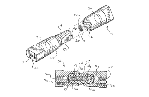
the preferred chromz~tograph3~ column 36 comprises a housing 1. The housing
1 consists of female. end fitting 2 and male end fitting 3. The female end
, , fitting and the portion of the: male end fitting other than arm 4 are
preferably
made from a conducaive material. Preferably, these pieces are made from
titanium or stainless steel coated with inert material. The male end fitting 3
has a threaded arm 4 secure,] thereto. The arm 4 of the male end fitting 3
WO 96127793 ~7 ~ ~ JC PCTlUS96/02780
-13-
further comprises a cavity 4b. The threaded arm is preferably made From a
non-conductive, water proof plastic material. The arm 4 of male end fitting 3
is most preferably made from polyetheretherketone (PEEK). The female end
fitting 2 also has a cavity 6. The cavity 6 is pieferabIy threaded and adapted
to receive the threaded arm 4 of male end fitting 3.
Housing 1 is easily assembled by releasably securing arm 4 of male end
fitting 3 in the cavity 6 of the female end fitting 2. This is accomplished by
simply screwing the threaded arm 4 of the male end fitting 3 into the cavity 6
of female end fitting 2. Similarly, the housing 1 may be just as easily
dismantled by unscrewing the threaded arm 4 of male end fitting 3 from the
cavity 6 of female end fitting 2. When the housing 1 is assembled, the cavity
4b of the arm 4 of male end fitting 3 provides part of an effluent flow
channel
9, which is adapted to permit fluid flow through the housing 1.
The male end fitting 3 has an opening 5, which is adapted to permit
fluid to enter or exit the housing 1. The female end fitting 2 also has an
opening 7 which is adapted to permit fluid to enter or exit the housing 1.
Preferably, openings 5 and 7 are threaded for easy connection to fluid lines
in
the chromatography apparatuses and methods described herein. Extending
from the opening 5 of male end fitting 3 to opening 7 of female end fitting 3
when the housing 1 is assembled is the effluent flow channel 9.
The housing 1 further preferably comprises first and second electrodes
11 and 13. Preferably, first and second electrodes l I and 13, respectively,
are
positioned at opposite ends of the effluent flow channel 9, and are positioned
such that the fluid flow through the housing 1 is from one of the first or
second electrodes to the other. In the most preferred embodiment, the
electrodes 11 and 13 are positioned near the openings 5 and 7 of the male end
fitting 3 and female 2 end fitting, respectively, of the housing 1.
The housing 1 further comprises chromatography packing material 15
disposed within the effluent flow channel 9. The chromatography packing
material 15 is selected as discussed with respect to the various embodiments
discussed below. Preferably, at least a portion of the chromatography packing
material is disposed between the first and second electrodes. However, in an
alternative embodiment of the present invention, those skilled in the art will
appreciate that, instead of using chromatography packing material 15, the
effluent flow channel 9 may be defined by chromatography material (not
shown). For example, chromatography material (not shown) may be coated on
the wall 9a of the effluent flow channel 9.
R'O 96/27793 218 7 2 8 5 PCT~596/02780
-14-
Alternatively, the wall 9a of effluent flow channel 9 may comprise
chromatography material such as a hollow tubing containing chromatography
stationary phases (not shown). One such material suitable for use in this
alternate embodiment is Nafion~ available from Perma Pure, Toms River, New
Jersey. In view of the foregoing, those in the art will appreciate, the term
"chromatography material" as used herein is meant to include chromatography
packing material 15 (such as those materials discussed herein), coatings of
chromatography material containing chromatography stationary phases (not
shown) coated on the wall 9a proximate to the effluent flow channel 9, hollow
tubing containing chromatography stationary phases, as well as other
stationary
phases commonly used in chromatography.
In a preferred embodiment, the electrodes l l and 13 are flow-through
electrodes. By flow-through electrodes, it is meant that the electrodes allow
the sample ions and eluant to flow therethrough. The electrodes are preferably
made from carbon, platinum, titanium, stainless steel or any other suitable
conductive, non-rusting material. The preferred flow-through electrodes are
sufficiently porous to allow the sample ions and eluant to flow therethrough,
but sufficiently non-porous to physically retain the pacling material 15
disposed in the effluent flow channel 9. The most preferred electrodes are
made of platinum coated titanium, ruthenium oxide coated titanium, titanium
nitride coated titanium, gold, or rhodium with an average pore size of between
O.llcm and IOOwm.
In a preferred aspect of the invention, the flow-through electrodes
comprise an annular surface 13a surrounding an inner meshed surface
comprising a frit 13b. Preferably, only the annular surface 13a is
electroactive; the inner frit surface I3b being made from a non-electroactive
material. The annular surface 13a may be made from any of the electroactive
materials described above. The inner frit surface 13b is preferably made from
PAT'" available from Systec (Minneapolis, MN), which is a non-electroactive
alkoy of TEFLON and PEEK. The foregoing electrode structure provides
certain advantages when the eluant comprises an organic substance. Methanol,
for example, is converted to formic acid if it comes into contact with a
charged
surface of the electrode. Thus, if the eIuant comprises methanol, it would be
converted to formic acid upon contacting the frit surface of the electrode if
the
frit was made from an electroactive material. Such a result is undesirahiP ;r,
'
that, among other things, the formic acid by-product could interfere with the
analysis. Malting the frit surface from a non-electroactive material minimizes
CA 02187285 1999-06-17
WO 96/27793 , PCT/US96/02780
-15-
the oxidation of methanol, which reduces undesirable by-products when the
eluant comprises organic :substances such as methanol.
In a most preferred aspect of the invention, the electroactive surfaces of
the electrodes 11 .and 13 are coated with a Nafion''" coating. Nafion''" is a
perfluorinated, hydrophilic;, proton conducting ion exchange polymer that
exhibits relatively high thermal stability and is not detrimental to the
kinetics of
electrochemical processes. Further information concerning the Nafion~'
coating may be ob twined from William T. Callaghan, Manager Technology
Commercialization JPL301350 4800 Oak Grove Drive, Pasadena, CA 91104.
When making such an inquiry refer to NP019204, Vol. 19, No. 6, NASA
Tech. Briefs, p. 66. The benefits of coating the electrode with NafionTM is
that, as
presently understood, the voltage required to obtain a given current may drop
by as much as twf:nty percent when the electrodes 11 and 13 are coated with
Nafion"'.
The electrodes 11 and 13 are connected to an electrical power source
(not shown) via a ,spade lu~, (not shown) which is secured in lug receptacles
Sa
and Sb of female end fitting; 2 and male end fitting 3, respectively, by a
screw
or some other similar means. When the power source (not shown) is turned
on, an electric current, caused by ion transport, is established from one of
the
first or second electrodes to the other across the chromatography packing
material 15 when the column is in use. Preferably, the electric current
follows
along a path that is parallel to fluid flow through the column. Most
preferably, the current is a constant current.
As described more fully below, the foregoing column can be used in
various apparatuses and methods of electroelution chromatography. The
column of the present invention may also be advantageously used as a
self regenerating chemical suppressor. In addition, the column of the present
invention can be used in a variety of other applications as well, which are
also
~ described herein.
A. Electroelution Elution Chromatoaranhv
Figs. 4-6 illustrate the preferred column of the present invention
especially adapted for use in preferred apparatuses and methods for
separating,
detecting, and analyzing sample ions by electroelution chromatography. As
used herein, the terns "electroelution chromatography" means eluting sample
components from a chromatographic column by electrochemically generating
WO 96127793
218 7 2 8 5 P~~S96102780
_16_
or modifying the mobile phase. In other words, the mobile phase is generated
or modified within or prior to entering the column by electrochemical action
on the eluant.
Fig. 4 is a schematic view of an apparatus for ion analysis by
electroelution chromatography using the preferred column of the present
invention. The present embodiment is discussed with respect to the detection
of anions in a sample. However, as discussed below, this embodiment may be
modified for ration analysis, or for the analysis of anions and rations in the
same test sample.
A water-containing eluant source 30 (preferably deionized water) is
introduced through a high pressure liquid chromatography (HPLC) pump 32.
As those skilled in the art will appreciate, a variety of pumps may be used in
this embodiment. However, a metal-free, reciprocating piston pump is
preferred, such as the ALLTECH Model 325 pump. The test sample, which
contains anions to be detected, is injected through an injector 34, and is
routed
by the eluant to column 36, which is preferably constructed as depicted in
Figs. 1-3. Again, as those skilled in the art will appreciate, a variety of
injectors may be used in the present embodiment. However, metal-free, rotary
6-port injection valves are preferred, such as those available from
IZHEODYNE (Model No. 9125) or VALCO. The column 36 comprises
chromatography packing material. For anion analysis, the column 36 is
packed with an anion exchange packing material (not shown). The anion
exchange packing material preferably comprises exchangeable hydroxide ions.
By "exchangeable," it is meant that the hydroxide ions on the packing material
may be displaced (or exchanged with) the sample anions. Suitable anion
exchange packing materials comprise particles of primary, secondary, tertiary,
or quaternary amino functionalities, either organic or inorganic. Preferred
anion exchange packing materials comprise quaternary amino functionality
organic or inorganic particles. These anion exchange particles may be packed
in the column in either resin form or impregnated in a membrane. Preferably,
the anion exchange packing material is in resin form.
The sample anions and eluant are routed through column 36. In
column 36, the sample anions displace the exchangeable hydroxide ions on the
anion exchange packing material, and are retained in the column 36. Either
just before or after the sample anions are retained in column 36, an electric
current is generated in column 36 by taming on electrical power supply 38.
As those skilled in the art will appreciate, a variety of electrical power
supplies
CA 02187285 1999-06-17
WO 96/37793 . PCT/US96/02780
- 17-
may suitably be used in the present embodiment. All that is required for the
electrical power supply is that it be capable of providing from about 5-5,000
volts, more preferably from about 28-2,800 volts, and most preferably about
10-1,000 volts to the electrodes in the methods of electroelution
chromatography described herein. However, a time-programmable
constant-current L~C power supply is preferred, such as the LABCONCO
Model 3000 Electrophoresis Power Supply. Preferably, the cathode (not
shown) of column 36 is located at an upstream end of the column 36, and the
anode (not shown) is located at a downstream end of the column 36.
Preferably, the electrodes .are positioned in the effluent flow channel (not
shown) of the column 36. When the water in the eluant contacts the cathode
(which is the electrode located at the upstream end of the column 36 for anion
analysis), it undergoes elecarolysis, and hydroxide ions are generated
according
to the following reaction:
Cathode: 2H20 + 2e- ---- > HZ(g) + 20H-
Similarly, when th~~ water :in the eluant contacts the anode (which is the
electrode located at the downstream end of the column 36 for anion analysis),
it undergoes electrolysis, and hydronium ions are generated according to the
following reaction:
Anode: 2H20 ----> 4H+ + OZ(g) + 2e
Thus, hydro:{ide ions and hydrogen gas are generated at the upstream end
of the column 36, ~~nd are routed through the column 36. The hydroxide ions
displace the retaineaj sample: anions on the anion exchange resin in column
36.
The anion exchange: resin is thus simultaneously regenerated back to its
hydroxide form while the sample anions are eluted. The released sample
~ anions and excess hydroxide: ions generated at the upstream located cathode
are
routed to the downstream end of the column 36 and combine with the
hydronium ions generated a1: the downstream located anode to form the highly
conductive acid of the sample anions and relatively non-conductive water,
respectively. The effluent from column 36 (e.g., the column effluent), which
contains the sample anions in their highly conductive acid form and the
relatively non-conductive water, is then routed downstream to a detector 42 in
which the sample anions are detected. The detector is preferably a
w0 96!27793 218 7 2 8 5 p~~S96102780
-18-
conductivity detector, such as the ALLTECH Model 350 Conductivity
Detector. The sample ions detected at the detector may also be quantified by a
data system (not shown). The data system is preferably a computer based
integrator, such as the HEWLETT-PACKARD General Purpose Chemstation.
Preferably, the effluent from the detector (e.g., detector effluent) is
then routed from the detector 42 through a backpressure regulator 44. The
backpressure regulator 44 keeps the gaseous HZ and 02 bubbles formed at the
cathode and anode, respectively, small enough so that they do not interfere
with the detector 42. The backpressure regulator is preferably a
spring-energized diaphragm system that maintains constant backpressure on the
system regardless of flow rate, such as the ALLTECH backpressure regulator.
The detector effluent can then be routed from the backpressure regulator 44 to
waste 46. Alternatively, before being routed to the detector 42, the column
effluent may be routed through a gas-permeable membrane tube (not shown)
positioned between the analytical column 36 and the detector 42. In that way,
the gas bubbles generated by the electrolysis of water may be released through
the gas permeable membrane to the atmosphere.
In a preferred embodiment, the detector effluent is routed from the
back-pressure regulator to an ion exchange bed 45. In anion analysis, the ion
exchange bed may be packed with anion exchange packing material (not
shown). The anion exchange packing material preferably comprises
exchangeable hydroxide ions, and is selected as previously described with
respect to column 36. The sample anions replace the exchangeable hydroxide
ions on the anion exchange packing material in the ion exchange bed, and the
released hydroxide ions combine with the hydronium counterions of the sample
anions to form water. The water may then be routed from the ion exchange
bed 45 to the water-containing eluant source 30. In this manner, a self
sustaining eIuant source is established. Of course, the anion exchange resin
in
the ion exchange bed 45 will eventually become exhausted, and thus it will
need to be periodically replaced or, in the alternative, regenerated according
to
the methods described herein.
A variety of anions can be separated, detected, and analyzed according
to the foregoing method. Examples include chloride ions, nitrate ions,
bromide ions, nitrite ions, phosphate ions, sulfate ions, as well as other
organic and inorganic anions. Figs. SA and SB are schematic views of column
36 wheri used in the foregoing method of anion analysis by electroelution
chromatography. In Fig. SA, the sample anions (X-) are retained on the anion
WO 96/27793 , ' 218 7 2 8 5 P~~S96102780
-19-
exchange packing material 46 that is packed in column 36. Turning to Fig.
5B, when the power source (not shown) is turned on, hydroxide ions generated
at the upstream located cathode of the column 36 are routed through the anion
exchange packing material and displace the retained sample anions X-. The
released sample anions (X-) combine with the hydronium ions generated at the
. downstream located anode of column 36 to form the highly conductive acid of
the sample anions (f~). Additionakly, the excess hydroxide ions generated at
the upstream located cathode combine with the hydronium ions generated at the
downstream located anode to form the relatively low conductive water.
Thereafter, the sample anions in their acid form are routed with water from
the
column 36 to the detector (not shown) where the sample anions are detected.
Based on the foregoing discussion, those stilled in the art will
appreciate that the electrodes can be Located either outside of or inside the
column 36. The only necessary condition with respect to the placement of the
electrodes is that at least a portion of the chromatography packing material
(anion exchange packing material in the foregoing embodiment) is disposed
between the two electrodes, and that fluid flow through the column is from one
of the electrodes to the other. Thus, when it is said that the electrode is
positioned at an upstream end of the column, it does not necessarily mean that
the electrode is actually located in the column. To the contrary, it is simply
meant that the electrode is located between the fluid source and the other
electrode. Similarly, by the term "downstream end" of the column, it is meant
that the electrode is located on the side opposite the fluid source relative
to the
other electrode. Again, the electrode is not necessarily positioned in the
column itself. Thus, fluid flow is always from the "upstream" located
electrode to the "downstream" located electrode.
Without being restricted to theory, it is presently believed that the
electrical current in column 36 is generated between the two electrodes via
ion
transport along the chromatography packing material (not shown) in the
column 36. However, where the packing material is not capable of ion
transport, it is presently believed that ion transport takes place via the
mobile
phase. This electric current via ion transport surprisingly occurs even when
the chromatography packing material and the ekuant may not inherently be
electrically conductive. Because the electric current is generated by ion
transport along the chromatography packing material in the effluent flow
channel (not shown) of column 36, the electric current through column 36 is in
the same direction as fluid flow through the column 36.
R'O 96!27793 , _ _ 2 ~ $ 7 2 8 5 PCT~S96102780
-20-
As those skilled in the art will understand, the electrical voltage
generated in column 36 must be of sufficient strength for the electrolysis of
water to occur. The strength of the current generated in column 36 is directly
proportional to the voltage applied at the electrodes, the cross-section area
of
the electrodes, and the capacity of the packing material in column 36 (e.g.
the
higher the capacity of the packing material, the lower the resistance is in
the
column 36). The strength of the current in column 36 is inversely related to
the distance between the two electrodes.
The above method and apparatus can also be adapted for the separation,
detection, and analysis of sample rations as well. For ration
analysis, the
column 36 is packed with ration exchange packing material.
The ration
exchange packing material preferably comprises exchangeable
hydronium ions.
Preferred ration exchange packing materials include acid
functionalized organic
and inorganic particles, such as phosphoric acid functionalized
organic or
IS inorganic particles, carboxylic acid funcionalized organic
or inorganic
particles, sulfonic acid functionalized organic or inorganic
particles, and
phenolic acid functionalized organic or inorganic particles.
The ration
exchange particles may be packed into the column in either
resin form or
impregnated into a membrane. The most preferred ration exchange
packing
materials are sulfonic acid functionalized particles. Most
preferably, the ration
exchange packing material is packed in the column in resin
form.
In ration analysis, the apparatus of Fig. 4 is further reconfigured
so that
the anode (not shown) is positioned at the upstream end of
the column 36 and
the cathode (not shown) is positioned at the downstream end
of the column 36.
2S Thus, when an electric current of sufficient strength is
applied, hydronium ions
are generated at the upstream located anode 36. The hydronium
ions are then
routed across the ration exchange packing material and displace
the previously
retained sample rations in the column 36. The released sample
rations and
excess hydronium ions generated at the upstream located anode
combine with
the hydroxide ions generated at the downstream located cathode
to form the
highly conductive bases of the sample rations and water,
respectively. The
sample rations, in their basic form, and relatively non-conductive
water are
then routed to detector 42 where the sample rations are detected.
Finally, the
detector effluent is preferably routed through ion exchange
bed 45, which
comprises ration exchange packing material (not shown). The
ration exchange
packing material preferably comprises exchangeable hydronium
ions, and is
selected as described above. The sample rations displace
the hydronium ions
J
WO 96127793 218 7 2 8 5 p~.~s96/02780
-21-
and are retained in the ion exchange bed 45, and the released hydronium ions
combine with the hydroxide counterions of the sample rations to form water.
The ion exchange bed effluent (which comprises water), is then routed to the
water containing eluant source.
With reference back to Fig. 4, in an especially preferred embodiment of
the present invention both cafion exchange packing material (not shown) and
anion exchange packing material (not shown) is packed in column 36.
Similarly, ion exchange bed 45 is packed with both ration exchange packing
material (not shown) and anion exchange packing material (not shown).
Preferably, the ration and anion exchange packing material comprise
exchangeable hydronium and hydroxide ions, respectively, and are selected as
previously described. In this embodiment, both rations and anions in the same
test sample may be analyzed according to the foregoing method of
electroelution chromatography. However, this configuration is also preferred
even when only rations or only anions are being detected as well.
However, when it is desired to separate both anions and rations in the
same sample, a sample comprising anions and rations to be separated is routed
through column 36. The sample rations are retained in column 36 on the
ration exchange resin and the sample anions are retained in column 36 on the
anion exchange resin. The polarity of column 36 is arranged depending on
whether rations or anions are to be eluted first. Where it is desired to elute
the rations frst, the anode (not shown) is located at an upstream end of
column 36 and the cathode (not shown) is located at a downstream end of the
column 36. The power source 38 is turned on to generate an electric current
across the anion exchange resin and ration exchange resin in column 36.
Hydronium ions are generated at the upstream located anode by the electrolysis
of the water-containing eluant as previously described. Similarly, hydroxide
ions are generated at the downstream located cathode as previously described.
The hydronium ions are routed through column 36, displacing the retained
sample rations and simultaneously regenerating the ration exchange packing
material back to its hydronium form. The released sample rations and the
excess hydronium ions generated at the upstream located anode combine with
hydroxide ions generated at the downstream located cathode to form the highly
conductive bases of the sample rations and the relatively non-conductive
water,
respectively.
The sample rations (in their base form) and water are then routed to
detector 42 where the sample rations are detected. The detector effluent may
R'O 96/27793 ~ ~ ~ ~ ~ ~pCT/US96102780
-22-
then be routed to the ion exchange bed 45 where the sample cations
are
retained by displacing the hydronium ions on the ration exchange packing
material in the ion exchange bed 45. The hydronium ions displaced from
the
canon exchange packing material combine with the hydroxide counterions
of
the sample canons to form water, which may then be routed to the water-
containing eluant source 30.
After the sample canons have been detected, the polarity of column
36
is reversed, so that the cathode (not shown) is located at an upstream
end of
column 36 and the anode (not shown) is located at a downstream end
of the
column 36. Hydroxide ions are generated at the upstream located cathode
and
hydronium ions are generated at the downstream located anode by electrolysis
of the water-containing eluant as previously described. The hydroxide
ions are
routed through column 36, displacing the retained sample anions and
simultaneously regenerating the anion exchange packing material back
to its
hydroxide form. The released sample anions and the excess hydroxide
ions
generated at the upstream located cathode combine with the hydronium
ions
generated at the downstream located anode to form the highly conductive
acids
of the sample anions and the relatively non-conductive water, respectively.
The sample anions (in their acid form) and water are routed to the
detector 42 where the sample anions are detected. The detector effluent
may
then be routed to the ion exchange bed 45 where the sample anions are
retained by displacing the hydroxide ions on the anion exchange packing
material in the ion exchange bed 45. The displaced hydroxide ions then
combine with the hydronium counterions of the sample anion to form
water
,
which may then be routed to the water-containing eluant source 30.
In another embodiment of the present invention, two columns as
illustrated in Fig. 1 can be arranged in series for use in methods
of detecting
canons and anions in the same test sample. With reference to Fig. 6,
a
water-containing eluant source 30 (again, preferably deionized water)
is
introduced through a high pressure liquid chromatography (FiPLC) pump
32.
A test sample containing both anions and canons to be detected is injected
through an injector 34, and is carried by the eluant to a first column
36 of the
present invention, which is packed with anion exchange packing material
(not
shown). The anion exchange packing material preferably comprises exchange-
able hydroxide ions, and is selected as previously described.
The sample anions displace the hydroxide ions on the anion exchange
resin and are retained in the first column 36. The first column effluent,
which
WO 96/27793 2 ~ g 7 2 g ~ PCTIUS96102780
contains the sample rations and displaced hydroxide ions, is routed to a
second
column 136. Column 136 is packed with ration exchange packing material
preferably comprising exchangeable hydronium ions, and is selected as
previously described. The sample rations displace the hydronium ions on the
ration exchange packing material and are retained in the column 136. The
released hydronium ions neutralize the hydroxide ions in the first column
effluent to form water. The water is then preferably routed through the
detector 42 (giving no signal), through an ion exchange bed 46, through valve
48 and back to the eluant source 30.
An electric current sufficient to electrolyze water is then generated in
column 36 across the anion exchange packing material by turning on electric
power supply 38. The cathode (not shown) of the column 36 is located at an
upstream end and the anode (not shown) is located at a downstream end of the
column 36. The water-containing eluant undergoes electrolysis at the upstream
located cathode thereby generating hydroxide ions and hydrogen gas as
previously described. The hydroxide ions generated at the upstream located
cathode are routed through the column 36 and displace the retained sample
anions on the anion exchange packing material thereby eluting the sample
anions from column 36.
At the downstream located anode of the column 36, hydronium ions and
oxygen gas are generated as previously described by the electrolysis of the
water-containing eluant. The released sample anions from column 36 and the
excess hydroxide ions generated at the upstream located anode of the column
36 combine with the hydronium ions generated at the downstream located
cathode of the column 36, to form the highly conductive acids of the sample
anions and relatively non-conductive water, respectively.
The acids of the sample anions and water from column 36 are routed
through column 136 unretained to detector 42, in which the sample anions are
detected and quantified by a data system 43. The bubbles formed by the
hydrogen gas and oxygen gas generated at the cathode and anode, respectively,
of the column 36 are kept small enough by back pressure regulator 44 so that
they do not interfere with the detector 42.
The detector effluent is then preferably routed from the detector 42
through back pressure regulator 44 to an ion exchange bed 46 comprising ion
exchange packing material having exchangeable hydronium and exchangeable
hydroxide ions. The ion exchange bed is preferably of high-purity such as
those used to produce deionized water. The sample anions displace the
R'O 96/27793 218 7 2 8 5 PCT~S96/02780
_24_ _ i
hydroxide ions and are retained in the ion exchange bed 46. The displaced
hydroxide ions neutralize the resulting hydronium counterions of the sample
anions to form water, which is preferably routed through valve 48 back to the
eluent source 30.
Once the sample anions have beendetected, an electric current
sufficient to electrolyze water is then generated in column 136 across the
ration
exchange packing material by turning on electric power source 138. The
anode (not shown) is positioned at an upstream end of the column 136 and the
cathode (not shown) is located at a downstream end of the column 136. The
water containing eluant undergoes electrolysis at the upstream located anode
of
the column 136 thereby generating hydronium ions. The hydronium ions are
then routed through the column 136 and displace the previously retained
sample rations on the ration exchange resin thereby eluting the sample rations
from column 136.
At the downstream located cathode (not shown) of column 136,
hydroxide ions and hydrogen gas are generated as previously described by the
electrolysis of the water-containing eluant. The released sample rations and
the excess hydronium ions generated at the upstream Located cathode of the
column 136 combine with the hydroxide ions generated at the downstream
located anode of the column 136, to form the highly conductive bases of the
sample rations and relatively non-conductive water, respectively.
The sample rations (in their base form) and water are then routed from
column 136 to detector 42, in which the sample rations are detected and
quantified by data system 43. Again, the bubbles formed by the hydrogen gas
and oxygen gas generated at the cathode and anode, respectively, of the
column 136 are kept small enough by the backpressure regulator 44 so that
they do not interfere with the detector 42.
The detector effluent is then preferably routed from the detector 42
through backpressure regulator 44 to the ion exchange bed 46. The sample
rations displace the exchangeable hydronium ions in the ion exchange bed 46
and are retained therein. The displaced hydronium ions neutralize the
hydroxide counterions of the sample rations to form water, which is preferably
routed through valve 48 back to eluant source 30.
Figure 7 is a chromatogram of a test sample containing both anions and
rations separated pursuant to the foregoing method and apparatus of the
present
invention. The first series of peaks represent the sample anions that are
eluted
when power is applied and an electric current is generated across the anion
WO 9612??93 218 l 2 8 5 pCTIUS96/02750
exchange packing material in column 36. The second series of peaks represent
the sample canons that are eluted and detected when power is applied and an
electric current is generated across the canon exchange packing material in
column 136.
As those skilled in the art will recognize, the foregoing apparatus and
method can be easily reconfigured so that the column 36 is packed with canon
exchange packing material and the anode is located at an upstream end and the
cathode is located at a downstream end of the column 36, and column 136 is
packed with anion exchange packing material and the cathode is located at a
upstream end and the anode is located at a downstream end of the column 136.
The foregoing methods and apparatuses provide many advantages. For
example, the strength of the current applied in the columns 36 and 136 will
determine the concentration of hydroxide and hydronium ions generated in
these columns. The higher the current, the greater the concentration of
hydroxide or hydronium ions and the easier and quicker the sample anions and
canons will be eluted. Thus, gradients are therefore possible through
time-based current programming in the anion and ration columns. Moreover,
the foregoing method can be configured as a closed loop system. Additionally,
simultaneous canon and anion analysis is possible with high sensitivity and
low
background noise. Moreover, water dips, and unretained counter-ration peaks,
and unretained counter-anion peaks often present in traditional ion
chromatography methods may be reduced and even eliminated.
The methods and apparatuses previously described can also be used in
methods and apparatuses for the electroelution of proteins, as well as any
other
test sample whose affinity for chromatographic packing material is affected by
Ph changes and/or ionic strength changes. Proteins and many other test
samples retain on affinity stationary phases by biological recognition, on
reversed phases by hydrophobic interactions, on ion-exchange or chelanon
packing materials by charge interactions, by size on size exclusion packing
materials, by hydrophobic interactions on hydrophobic packing materials, and
by normal phase interactions on normal phase packing materials. All of these
retention mechanisms may be mediated by ionic strength and/or Ph. By using
the electrolysis of water as discussed in the foregoing embodiment, the
hydrogen and hydroxide ion concentration in the column illustrated in Fig. 1
can be controlled, thereby permitting the control of the Ph and ionic strength
inside the column. Thus, by pacling the chromatography column of the
present invention with an ion-exchange, affinity stationary phase, reversed
R'O 96127793 ' PCT/US96/02780
_26-
phase, size exclusion, chelating, hydrophobic, or normal phase
chromatography packing material, proteins or other samples can be retained
when no power is applied to the column. However, when power is applied to
generate hydronium ions (decrease Ph) or hydroxide ions (increase Ph) within
the column, the resulting ionic strength and l'h change may be used to elute
the
retained protein (or other samples) from the column. Thus, the column of the
present invention can be used to separate and purify a wide range of
compounds on both an analytical and preparative scale.
Suitable packing materials for use in the foregoing embodiment include
Protein A affinity packing material as the affinity phase packing material; C-
18
reversed phase packing material as the reversed phase pacling material;
Chelex-100 from Bio-ltad in the chelating packing material; ALLTECH
Macrosphere GPC as the size exclusion packing material; SYNCHROM
SynChropak HIC as the hydrophobic packing material; and ALLTECH Akltima
Silica as the normal phase packing material.
Additionally, as discussed below, the column of the present invention
can also be used as a self regenerating solid phase chemical suppresser in
various apparatuses and chromatography methods.
B. Electrochemically Regenerated
Solid Phase Chemic l Snp rp essor
1. system Configurations for Anion Ana1_yc~,c
Figures 8A-8D are schematic views of various preferred apparatus
configurations for a preferred method of ion analysis using the column
illustrated in Fig. 1 as a self regenerating solid phase chemical suppresser.
With reference to Fig. 8A, an eluant source 202 is in fluid connection with a
pump 204. Downstream from the pump 204 is an injector 206 where a test
sample can be added to the system. Located downstream from the injector 206
is an analytical (or chromatography) column 208 where separation of the ions
in the test sample occurs. In anion analysis, a low-capacity anion exchange
column is preferably used. For ration analysis, a low-capacity ration exchange
column is preferably used.
Located downstream from, and in fluid connection with, the analytical
column 208, is a 10-port switching valve 210. The switching valve is
preferably of the metal-free rotary type. In connection with the 10-port
switching valve 2k0 are two columns, 212 and 214, respectively, as illustrated
in Fig. I. Connected to columns 212 and 214 are electrical power sources
WO 96127793 218 7 2 8 5 pCTlUS96/02780
-27-
216a and 216b, respectively. One power source connected to
both columns
212 and 214 may be used as well. This embodiment generally
requires lower
voltage than the foregoing methods of electroelution chromatography
because
the capacity of the chromatography packing materials in this
embodiment is
greater (e.g, lower resistance), and thus lower voltages
are capable of
generating a current sufficient for the electrolysis of water.
A preferred power
source is the KENWOOD PR 36-1.2 power supply. When the column
illustrated in Fig. 1 is used as a suppressor, the power
source should be
capable of delivering about 1-100 volts to the electrodes,
more preferably
about 10-90 volts, and most preferably about 3-15-volts.
Finally, a
conductivity detector 218 is connected with 10-port switching
valve 210. As
described in more detail below, the column illustrated in
Fig. 1 is adapted for
use as a self-regenerating solid phase chemical suppressor
in the foregoing
configuration.
Still with reference to Fig. 8A, an aqueous eluant source
202 introduces
eluant through a HPLC pump 204. A test sample containing
anions to be
detected is injected through injector 206, and is routed
by the eluant to
analytical (or chromatography) column 208. In the present
embodiment (e.g.,
anion analysis) the eluant may comprise solutions of sodium
carbonate, sodium
bicarbonate, sodium hydroxide or some other base that is
converted to a weak
acid by counterion exchange with hydronium ions. The most
preferred eluant
for anion analysis are solutions of sodium hydroxide.
The analytical column 208 is preferably packed with anion
exchange
packing material (not shown). Suitable anion exchange packing
materials
comprise particles of primary, secondary, tertiary, or quaternary
amino
functionalities, either organic or inorganic. The preferred
anion exchange
packing materials comprise quaternary amino functionality
organic or inorganic
particles. These anion exchange particles may either be packed
into the
column in resin form or impregnated into a membrane. Preferably,
the
packing material is in resin form.
Different anions in the test sample have differing affinities
for the anion
exchange packing material in the analytical column 208. The
stronger the
affinity of a particular type of anion for the packing material
in the analytical
column 208, the longer that type of anion will be retained
in the column 208.
Conversely, the weaker the affinity of a particular type
of anion for the
packing material in the analytical column 208, the shorter
that particular type
of anion will be retained in the column 208. Thus, because
different anions
;, , ,
WO 96127793 PCTIU596I02780
-2g _ ~ 187285
have different affinities for the packing material in column 208, the sample
anions are eluted at different speeds from the column 208 and are therefore
separated or resolved.
The effluent from analytical column 208 (hereinafter referred to as
"chromatography effluent") is routed from the column 208 through 10-port
switching valve 210 to column 212. In this embodiment, the column 212 is
adapted for use as a suppressor in a method of anion analysis. The column
212 is packed with ration exchange packing material (not shown). Preferred
ration exchange packing materials include acid functionalized organic or
inorganic particles, such as phosphoric acid functionalized organic or
inorganic particles, carboxylic acid functionalized organic or inorganic
particles, phenolic acid functionalized organic or inorganic particles, and
sulfonic acid functionalized inorganic or organic particles. The ration
exchange particles may either be packed into the column in resin form or
impregnated into a membrane. The most preferred ration exchange packing
materials are sulfonic acid functionalized inorganic or organic particles in
resin
farm.
Two ion-exchange reactions take place in the suppressor 212:
1. Eluant:
(where the eluant is sodium hydroxide and the ration exchange
packing material comprises sulfonic acid functionalized
particles):
NaOH + Resin - S03 H* ----> Resin - SO3 Na* + Hz0
2. Analyte:
NaX + Resin - S03 H* ---> Resin - S03 Na* + HX
(where X = anions such as C1, NO,, Br etc.)
The sodium ions in the high conductivity eluant are removed by ion exchange
with the hydronium ions present on the ration exchange packing material in the
column 212. The high conductivity sodium hydroxide eluant is thus converted
to the relatively non-conductive water (the sample counterions are also
suppressed by ion exchange with hydronium ions on the ration exchange
packing material). This, of course, reduces the background noise from the
eluant (and sample counterions) when the sample anions are ultimately detected
in the detector 218. The sample anions are converted into their highly
conductive acid form by exchanging their counterions with hydronium ions on
WO 96127793 218 7 2 8 5 P~'~596/0278D
-29-
the ration exchange packing material in the column 212. As can be
ascertained from the above reactions, the eluant in anion analysis can be any
salt solution that forms a weakly conductive acid in the Suppresser 212.
Examples of suitable eluants include aqueous solutions of sodium hydroxide,
sodium carbonate/bicarbonate, and sodium tetraborate. The eluant must
further comprise water, however, to feed the electrolysis in the methods of
the
invention.
After the eluant has been converted to its weak acid and the sample
anions to their highly conductive acids in the column 212, the suppresser
effluent is routed through the 10-port switching valve 210 to detector 218
where the sample anions are detected. Data from the detection of the sample
anions is preferably recorded on a chart, graph, an integrator, a computer, or
other recording means (not shown). The effluent from the detector 218
(hereinafter referred to as "detector effluent") is then routed through 10-
port
switching valve 210, and column 214 to waste.
When the ration exchange packing material in suppresser 2I2 is
exhausted (e.g., completely converted from the hydrogen to sodium form), a
sharp increase in the conductance of the suppresser effluent is observed.
Before this happens, the 10-port switching valve 210 is switched to the
configuration depicted in Figure 8B. While using the column 214 to suppress
the chromatography effluent in the same manner as previously described with
respect to column 212, the detector effluent is recycled back through 10-port
switching valve 210 to the exhausted suppresser 212 to regenerate it as
follows.
A power source 216a is turned on thereby generating an electric current
sufficient for the electrolysis of water across the exhausted ration exchange
packing material in suppresser 212. Suppresser 212 is configured so that the
anode (not shown) is positioned at the upstream end and the cathode (not
shown) is positioned at the downstream end of the suppresser 212. The
detector effluent (which contains water) undergoes electrolysis at the
upstream
located anode of suppresser 212 as previously described:
2H20 ----> 4 H* + OZ + 4e
Hydronium ions and oxygen gas are thus generated at the upstream anode of
suppresser 212. Since the detector effluent is flowing from the anode side to
the cathode side of the suppresser 212, the hydronium ions are routed across
WO 96127793 218 7 2 8 5 PCT~S96I02780
-30-
the exhausted ration exchange packing material in suppresser 212 converting it
back to the hydrogen form according to the following reaction:
Resin-SO;Na* + H* -> Resin-SO3H* + Na*
The oxygen gas and displaced sodium ions (and sample counterions) from
suppresser 212 are then routed through 10-port switching valve 210 to waste.
At the downstream located cathode of suppresser 212, water undergoes
electrolysis as previously described:
2Hz0 + 2e ---- >- Hi + 20H~
Hydroxide ions and hydrogen gas are thus generated at the downstream end of
suppresser 212. The hydroxide ions and hydrogen gas generated in suppresser
212 are routed through 10-port switching valve 10 to waste.
Alternately, the systems waste products may be recycled. As can be
appreciated from the above chemical reactions, the regeneration process
liberates exactly the same mass of eluant ions consumed during the suppression
process. Because the process is quantitative, routing the waste products from
switching valve 10 back to eluant source 2 on a continuous basis will result
in
continuous reconstitution of the original eluant (in this embodiment sodium
hydroxide), eliminating chemical waste.
Power source 216a is left on long enough to regenerate the ration
exchange packing material in suppresser 212. Once the suppresser 212 is
regenerated, the power source is fumed off. The detector effluent is still
preferably routed through the suppresser 212, however, for a time sufficient
to
purge any remaining gas bubbles and electrolysis products in suppresser 212,
and to equilibrate the column. Once the suppresser 212 is regenerated and
equilibrated, it is ready for use as the "active" suppresser when suppresser
214
becomes exhausted. Once suppresser 212 is ready to go back on line, the
analytical column effluent is re-routed to suppresser 212 and suppresser 214
is
regenerated in the same manner as previously described with respect to
suppresser 212.
The foregoing arrangement allows endless cycling between the two
suppressers 212 and 214 for continuous instrument operation without
interruption or suppresser replacement. Preferably, when the eluant comprises
an organic such as methanol, after regeneration the eluant is allowed to pass
CA 02187285 1999-06-17
WO 96rZ7793 ~ PCT/US96/02780
-31-
through the suppressor fox a time (usually about S minutes) sufficient to wash
unwanted components that may remain in the suppressor after regeneration.
Once these unwanted by-products are purged from the suppressor, the sample
to be analyzed may then be injected into the system. The system is easily
automated using automatic; valves and power supplies to provide unattended
operation for extended periods.
In one aspect of the invention, a computer program is used to
implement and auvtomate the switching between suppressors. One presently
preferred flowchart providing an overview of such computer program and its
functions is provided in Figs. 23(a)-(c).
In a presently preferred embodiment, the above-referenced computer
program will be used to run. a self contained suppressor system comprising two
,solid-phase electrochemical. suppressors packed with ion exchange resin, a
two
position electrically actuated 10-port switching valve, a constant current
power
supply and a microprocessor. These components are preferably housed together
in
one housing. A suitable microprocessor is the MOTOROLA 8-bit microprocessor
(Motorola Part No. 68HCPli 1 A1 FN) operating with a 4 mHz crystal, 32 K x 8
EPROM, National Part No. 27C256 and 8K x 8 RAM, MOSEL Model Part No. MS
6264C-80PC.
With respe~~t to this. suppressor system, the mobile phase from the
separator (or anal~~tical) column flows through one suppressor at a time.
While one suppressor is being used, the other is electrochemically regenerated
and equilibrated. 'The valve switches between suppressors after each sample
injection, providin;; a fresh suppressor cell for each analysis. Preferably,
the
suppressors will be: of relatively small volume to avoid problems such as band
broadening, Donnan exclusion, and the oxidation of nitrite to nitrate
associated
with conventional packed-bed suppressors. The suppressors are preferably
either 7.0 by 7.5 mm or 14 x 7.5 mm in internal diameter. Finally, the
operator interface on the front panel of the suppressor unit has a series of
' buttons or keys (which are discussed below) for easy operation of the unit
by
lab personnel.
CA 02187285 1999-06-17
R'O 96/27793 ~ PCT/US96/02780
-32-
The ion exc;hange resin in the suppressors is preferably visible when the
suppressors are hovused in the suppressor unit so that suppressor status may
be
monitored at all tirnes. This is accomplished by housing the suppressors in a
compartment having a transparent cover on a front panel or operator interface
of the unit. The suppressor status may be indicated by coating the ion-
exchange resin with an inert dye, which changes color as the suppressor resin
becomes exhausted. For anion analysis, the suppressors are packed with cation
exchange resin in tlhe hydrogen form, and the resin is coated with an inert
dye
comprising quinald:ine red. The unexhausted resin thus has a gold color,
which changes to magenta during suppression as the hydrogen ions on the resin
are replaced by the mobile ~ohase and sample counterions. For cation analysis,
the suppressors are packed with anion exchange resin in the hydroxide form,
and the resin is coated with an inert dye comprising thymolphthalein. The
unexhausted resin thus has a blue color, which changes to beige during
suppression as the hydroxide ions on the resin are replaced by the mobile
phase and...sarnple: caunterions:~
A flowchart providing an overview of software for use with Alltech's
ERISTM 1000 Autosuppresso:r is at Figs. 23(a)-(c). Among other things, the
software automatical'.ly coordinates suppression and regeneration based on
data
.inputted by the operator and based on signals received from other external
devices in
the chromatography system. The software also generates messages on a system
display concerning operational parameters, regeneration parameters and status
and
system errors. The system display is preferably a four line alpha numeric
display
and is positioned on the operator interface of the suppressor unit.
With reference to Fi;;s. 23(a)-(c), Step 500 is the beginning of the
software and depicts the startup screen when the suppressor unit is powered-
up. Program flow then proceeds to step 501. At step 501, a message is
generated on the system display indicating the "Active" method, which is the
method presently inlputted in the system for the next sample injection. The
'
WO 96/27793 ~ 218 7 2 8 5 PCT~596102780
-33
"Active ID" has a one or two digit number having associated pre-assigned
parameter values for a given method. The system may store up to twelve
different "Active ID" numbers, each having pre-assigned method parameters.
The system comes with two preassigned "Active ID" "numbers," EPA-A and
EPA-B (EPA Method 300, parts A and B, respectively). If selected, "EPA-A"
or "EPA-B" will appear on the system display as the "Active ID".
Additionally, ten "Active ID" numbers (e.g. 1-10) may be inputted into the
system wherein each number has its own unique operating parameters. In
addition to calling up any one of the twelve Active ID numbers having pre-
10. assigned parameters, new operating parameters may also be inputted into
the
system for a particular sample run by depressing the "Select Method" button
on the operator interface. The procedure for inputting new operating
parameters will be discussed in more detail below.
Referring back to the message at step 501, the three digit number
underneath the "Type" heading provides information concerning the type and
capacity of the individual suppressors. In step 501, the three numbers
corresponding to the "type" heading are "312." The first digit (e.g., "3")
refers to the type of sample analysis (i.e., either anion or ration analysis),
and,
thus, the type of suppressor in the system. The system will automatically set
the polarity of the electrodes based on this entry. For example, the
number "3" signifies anion analysis. This tells the system to configure the
electrode positioned at the detector effluent end of the suppressor as the
anode.
Conversely, if the number "2" were entered in place of "3" the system would
automatically reverse the polarity of the electrodes making the electrode
positioned at the detector effluent end of the suppressor the cathode. The
next
two digits under the "Type" heading (e.g., "12") refer to the capacity of the
individual suppressors in milliequivaIents (meq.) times 10. Thus, the screen
at
step 501 indicates a suppressor for anion analysis having a capacity of 1.2
milliequivalents. In a preferred embodiment, the suppressors themselves will
have a label or some other attached means for displaying a three digit number
to correspond to the "Type" number discussed above. Thus, for example, a
suppressor bearing the number "312" is for anion analysis and has a capacity
of 1.2 milliequilvaIents. As those skilled in the art will appreciate, the two
suppressors should have the same capacity in this embodiment.
Still with respect to the message generated at step 501, the "Flow"
heading refers to the flowrate in mL/min. for the analysis. The screen at
step 501 indicates a flowrate of 1.0 mL/min. The "Cone" heading in the
R'0 96127793 PCT/US96102780
_ X187285
-34-
message generated at step 501 refers to the concentration of the mobile phase
in miIliequivalents/Liter (meq./L). For anion analysis, the meq./L of rations
in the mobile phase is indicated. Conversely, for canon analysis, the meq./L
of anions in the mobile phase is indicated. Because the message at step 501
indicates anion analysis, the concentration of 4.0 meq./L refers to the
concentration of rations in the mobile phase. Finally, the "Time" heading in
the message generated at step 501, refers to the total run time for the
analysis
to a tenth of a minute.
To exit the screen at step 501 and proceed to the next screen the
operator merely depresses an "Enter" button on the operator interface and
program flow will proceed to step 502. In step 502 a message is generated on
the system display asking whether the operator wishes to proceed with the
method having the parameters indicated at step 501. If yes, the operator will
then depress a "NextJYes" button and then the "Enter" button on the operator
interface and program flow proceeds to step 503. If the answer is "No," then
the operator may depress a "Back/No" button and then the "Enter" button on
the operator interface to recall the screen at step 501. The operator may then
edit the parameters indicated at step 501 by depressing a "Select Method"
button key on the operator interface. Details concerning inputting new method
parameters are discussed in further detail below.
Referring back to step 503, a message is generated on the system
display requesting that the suppresser ("Cell") color be checked. If the color
condition is "O.K.," that is, if the color indicates that the suppressers are
in a
condition to accept a sample injection, the operator may depress the
"Next/Yes" and then the "Enter" buttons on the operator interface and the
program flow proceeds to step 504. The system is now ready to receive a
sample injection.
The system is programmed to switch between suppressers after each
sample injection. Samples may be injected manually or automatically. For
manual injection, an "InjecUStart" button is provided on the user interface,
which should be depressed simultaneously with the introduction of the sample.
Additionally, pins located on the rear panel of the operator interface are
designed to accept a sample injection signal from an external device such as
an
autosampler or a manual injection valve equipped with a position sensing
switch. While waiting for a sample injection, the system will cycle the mobile
phase between the two suppresser cells. Once the total analysis time elapses
for the particular method inputted into the system, the system will
WO 96/27793 ~ ~ ~ ~ PCT/US96/02780
-35-
automatically direct the mobile phase to a fresh suppresser and will begin
counting down the total analysis time. Upon receiving an injection signal, the
system resets the total analysis time, but continues directing column effluent
to
the active suppresser (because the new suppresser has not yet "seen" an
injection). The valve will automatically rotate to the other suppresser the
next
time the system receives an injection signal or when the analysis time has
elapsed, whichever comes first. The system software thus ensures that only
one sample injection is allowed to flow through the suppresser between
regeneration cycles regardless of when the sample is injected.
Referring back to step 504, a message is generated on the system
display pertaining to the "Method ID". The Method m indicates the current
operating parameters (e.g., cell type, flowrate, eluant concentration and
analysis run time), and the time remaining until the sample analysis is
complete. While one suppresser is in the suppressing mode the other
suppresser is regenerated by the electrolysis of the detector effluent. By
depressing the "Next/Yes" button on the operator interface, a message is
generated at step 505. This screen shows the total regeneration (or flushing)
time in minutes and seconds (min.aec), the remaining regeneration time (or
flushing) time (min.aec.), how much current is applied to the electrodes in
the
suppresser being regenerated, and the voltage across the suppresser being
regenerated.
Based on the flowrate, mobile phase concentration and total run time
entered for the particular method, the system automatically calculates the
amount of current required to completely regenerate the suppresser within 40%
of the run time. A negative voltage indicates that the suppresser being
regenerated is for anion analysis. A positive voltage indicates that the cell
being regenerated is for ration analysis. The message at step 505 indicates
that
the left suppresser is being regenerated while the right suppresser is in the
active or suppressing mode. The operator may toggle between the screens
displayed in steps 504 and 505, respectively, by depressing the "Next/Yes" and
"Back/No" buttons on the operator interface. The current is applied to the
suppresser undergoing regeneration just long enough to regenerate the
suppresser (as calculated by the system based on the method parameters) and
then the current is automatically shut off when regeneration is complete.
However, detector effluent continues to flow through the regenerated
suppresser to purge any remaining gas bubbles and other electrolysis by-
products.
WO 96127793 PCTIUS96102780
2187285
-36-
The operator interface also has a cell (e.g., suppresser)
status display.
This display indicates the cell is "IN USE", and whether
the other cell is either
being "REGEN" (e.g., regenerated) or is "READY" (i.e., regeneration
has
been completed). The suppressers are positioned in a compartment
on the
S operator interface and the compartment has a transparent
door so that the
suppressers are visible to the operator. The cell status
display is positioned
above the compartment housing the suppressers and comprises
a separate
display for each of the "LEFT" and "RIGHT" suppressers, respectively.
Thus, for example, if the LEFT suppresser is on line (i.e.,
in the active or
suppressing mode), the cell status display for the "LEFT"
suppresser will
display an "IN USE" message. While the LEFT suppresser is
in use, the cell
display for the "RIGHT" suppresser will display either a
"REGEN" or a
"READY" message, depending on whether the "RIGHT" suppresser
is being
regenerated or regeneration has been completed, respectively.
If for any reason the operator desires to regenerate both
of the
suppressers in the system, the operator may depress a "FULL
REGEN" (e.g.
Full Regeneration) button on the operator interface. Program
flow then
proceeds to step 511. The "FULL REGEN" button may be depressed
at
anytime during the display of the "Method ID" screen. A message
is
generated on the system display at step 511 asking for confirmation
that
suppresser regeneration is desired. By depressing the "Next/Yes"
button on
the operator interface, program flow then proceeds to step
512 where a
message is generated on the system display requesting the
operator to "Check
Cell Condition". If the color of the resin in the suppressers
indicates that the
suppressers are in the unexhausted form, the operator may
depress the
"Next/Yes" and then the "Enter" buttons on the operator interface
and program
flow proceeds to step 504. In which case, the system is ready
to receive a
sample injection. Conversely, if the resin color indicates
that the suppressers
are exhausted, and thus regeneration is desirable, the operator
may depress the
"Back/No" and then the "Enter" buttons on the operator interface
and program
flow proceeds to step 513.
The system then begins to regenerate both of the suppressers,
and a
message is generated on the system display at step 513 giving
the total time
(min.aec.) required to regenerate both suppressers and the
remaining time
(min.aec.) until both suppressers are regenerated. Again,
the time to
regenerate the suppressers is calculated by the system based
on the operating
or method parameters inputted by the operator. Only one suppresser is
WO 96/27793 -- 218 7 2 8 5 PCT~S96102780
-37-
regenerated at a time, and specific information concerning the suppresser
being
regenerated may be obtained by depressing the "Next/Yes" button on the
operator interface at Step 513 and program flow will proceed to step 514. At
step 514 a message similar to that generated at step 505 is generated on the
system display. This message reports on the status of the suppresser
undergoing regeneration at that moment, which in step 514 is the left
suppresser. The operator may toggle between screens 513 and 514 by
depressing the "NextlYes" and "Back/No" buttons on the operator interface.
Once both the suppressers are regenerated, program flow then proceeds to
step 504 and the system is ready to accept a sample injection. Also, the
program allows for aborting regeneration of the suppressers at any time by
simply depressing the "Enter" button on the operator interface at step 513.
This will abort the regeneration sequence and program flow will proceed to
step 503.
IS Method parameters may be entered or changed at the beginning of the
software, or at any other time by simply depressing the "Select Method" (Step
520) button on the operator interface. Program flow then proceeds to
step 521. At step 521, a message is generated on the system display indicating
the method parameters. By depressing the "Next/Yes" and "Back/No" buttons
on the operator interface the operator may scroll through the parameters -
Type, Flow, Conc. and Time. Arrow buttons on the operator interface are
used to increase or decrease the numerical values for each of these
parameters.
Once the desired operating parameters are set, the "Enter" button on the
operator interface is depressed and program flow then proceeds to step 522. A
message is generated on the system display at step 522. If the operator wishes
to proceed with the method parameters selected at step 521, the "Next/Yes"
and then the "Enter" buttons are depressed at step 522 and program flow
proceeds to step 504 and the system is ready to accept a sample injection.
Conversely, if the operator does not wish to proceed with the parameters
selected in step 521, the "Back/No" and then the "Enter" buttons are depressed
on the operator interface at step 522 and program flow proceeds back to
step 521.
When selecting method parameters at step 521, certain considerations
must be taken into account. When entering the three digit number for "Type"
of method, the type of analysis (i.e., whether cation or anion analysis) and
the
capacity (in meq./L) of the suppressers in the system must be entered. When
entering the flow rate (e.g., "Flow"), the operator must match the flow rate
WO 96127793 ~ ~ ~ ~ ~ PCTIITS96102780
-38-
with that of the HPLC pump in the chromatography system.
When entering
the concentration of the mobile phase ("Conc. "), the concentration
(in meq./L)
of the mobile phase counter-ions of the sample ions must
be entered.
Exemplary calculations and a list of meq/L. values for common
mobile phases
are provided in Appendix C to the Operator's Manual in the
Appendix.
Finally, the total run time ("Time") for the analysis to
the tenth of a minute
must also be entered. Additionally, as discussed previously,
up to ten pre-
assigned method parameters may be inputted into the system
by following the
previous steps.
With respect to an analysis for which the run time is unknown,
the
operator should enter the longest run time that is considered
appropriate for the
analysis. After running the analysis, the actual run time
may be re-entered by
simply depressing the "Select Method" button on the operator
interface and
scrolling through the parameters as discussed above.
Before accepting a method entered at steps 520-522, the system
will
check to confirm that the suppresser capacity is sufficient
to complete the
analysis within 40% of the total run time and that the power
supply can
generate enough current to complete regeneration within 40%
of the total run
time. If the suppresser capacity is insufficient, program
flow proceeds to step
523 where a message is generated on the system display stating
that there is a
"cell [e.g. suppresser] type and method mismatch." The operator
will either
need to replace the suppressers with suppressers having greater
capacity, or
change the method parameters by reducing the mobile phase
concentration,
flow rate or run time. The method parameters may be re-set
by depressing the
"Enter" button on the operator interface at step 523 and
program flow will
revert back to step 521, where the method parameters may
be selected as
previously discussed. If the power supply does not have enough
current to
timely regenerate the suppresser (i.e. within 40% of the
run time), program
flow proceeds to step 524 where a message is generated on
the system display
stating that "flow or cent. too high". The operator will
need to reduce the
mobile phase concentration or the flow rate. As a general
rule, the product of
the concentration in meq./L and the flowrate in ML/min. should
be equal or
less than 22.5 (cent. x flowrate <22.5). In any event, the
operator may
change the parameters relating to mobile phase concentration
or the flowrate
by depressing the "Enter" button on the operator interface
at step 524 and
program flow will revert back to step 521, where the method
parameters may
be selected as discussed.
WO 96/27793 2 1 8 7 2 8 5 p~~S96I02780
-39-
Based on the foregoing discussion, one skilled in the art will appreciate
that the system software will not allow method parameters that exceed 40% of
the capacity of the individual suppressors. This limit is to ensure that,
regardless of when a sample injection is received by the suppressor system, an
individual suppressor will never achieve full exhaustion. For example, a
suppressor could have mobile phase flowing through it for almost the entire
analysis time before receiving a sample injection. Thus, in a "worst case"
scenario, the suppressor could, at most, be nearly 40% exhausted before the
sample injection reaches the suppressor. The suppressor, which is 4030
exhausted when it finally receives a sample injection, will nonetheless still
have 60% of its suppression capacity. Because the system does not accept
operating parameters that will exceed 40 ro of an individual suppressor's
capacity, the suppressor will be able to complete the analysis with about 20
of its capacity still remaining. Thus, the suppressor should theoretically
never
exceed 80 k exhaustion in the system. As those skilled in the art will
appreciate, in the above-described system, the maximum useful cell capacity is
actually 80% of label capacity.
The system further has a variety of pre-programmed sub-routines
relating to system errors. For example, if the voltage across a suppressor
exceeds a pre-assigned value at any time during regeneration, an error message
is generated on the system display at steps 530, 530a or 530b, depending on
what mode of operation the system is in when the error occurs. This message
will indicate which of the suppressors in the system has failed, and the
system
will automatically go into a standby mode. Such an error indicates that there
is too much resistance in the suppressor to achieve regeneration within 40% of
the sample run time, and the suppressor should be checked. The upper pre-
assigned voltage limit is the upper voltage limit of the system power supply.
Similarly, if the voltage across a suppresser is below a pre-assigned value at
any time during regeneration, an error message is generated on the system
display at step 531. Such an error indicates that a short circuit has occurred
between the electrodes. In any event, once the voltage problem is corrected,
the system power is cycled and program flow reverts back to step 500.
Alternatively, the system may be programmed such that, once the voltage
problem is eliminated, the program flow reverts back to entry point B by
depressing the "Enter" button on the operator interface.
Another error sub-routine is triggered if the cover of the suppresser
compartment on the front panel of the unit is open. In such an event, system
CA 02187285 1999-06-17
WO 9027793 PCT/US96/02780
-40-
operation is intemipted and a message is generated on the system display at
step 540. A flashing light on the operator interface is triggered as well. If
the
cover is closed within a pre-assigned period of time, the system will resume
operation. If, however, the cover is not closed before passage of this pre-
assigned period of time, program flow then proceeds to step 541. Once the
cover is closed, program flow then proceeds to entry point A. Alternatively,
system operation may be aborted when the cover is open by pressing the
"Enter" button at step 540, and program flow proceeds to step 541.
Yet another error sub-routine is triggered if the HPLC pump in the
system is either off' when tt;ue system is powered-up or if the pump shuts
down
during system operation. In either event, the system goes into a standby mode
and a message is gf:nerated on the system display at step 550. Once the
problem is correctea3, program flow proceeds to either entry point A (if the
problem occurred while the system was running) or to entry point B (if the
system was powered-up with the pump off).
The system is also capable of Remote Out-Put via "Remote Out" pins
preferably positioned on the rear panel of the operator interface. The system
will send a "Not Ready" signal to external devices such as an automatic sample
injection system when the system is not ready to receive a sample injection.
The system sends the "Not heady" signal to external devices until the system
is ready to receive a sample injection, which is at step 504. The "Not Ready"
signal can also serve: as a safeguard if a system failure occurs. Thus, if any
of
the error sequences discussed above is triggered, a "Not Ready" signal is
T
transmitted to peripheral devices. Additionally, when the system is in the
"Full Regen" mode rind both suppressors are thus being regenerated, a "Not
Ready" signal is likewise sent to external devices.
Conversely, tike system is also capable of receiving Remote In-Put via
"Remote In" pins preferably ;positioned on the rear panel of the operator
interface. The systern may accept an error signal from other external devices.
, When it receives such an error signal, the system will automatically go into
a
standby mode.
The preferred columns for the suppressors used in the system are made
of a clear, cylindrical shaped, polymethylenepentane material. The electrode
and column end fittin;;s comprise a unitary piece. A sintered frit made from
an alloy of PEEK and TEFLON is pressed fitted into the end fitting.
WO 96/27793 218 7 2 8 5 PC'I'~1596/02780
-41-
The above described suppresser unit is preferably used in combination
with other external devices in a chromatography system. The other external
devices suitable for use with the self contained suppresser unit discussed
above
include an HPLC pump capable of low-pulsation solvent delivery with
flowrates preferably ranging from 0.01 mL/min. to lOmL/min. A preferred
pump is the ALLTECH Mode1526 or Model 426 HPLC pump. Also included
in the chromatography system is a detector capable of measuring the analyte.
A preferred detector is the ALLTECH Model 550 conductivity detector with a
temperature controlled cell compartment adjustable from ambient to 60~C,
which eliminates thermally-induced baseline noise and drift. Also included is
a
strip chart recorder or data system capable of accepting analog voltage data.
An autosampler or manual injection valve for sample introduction. An ion
chromatography column capable of separating the species of interest. And,
optionally, a guard column packed with material similar to the packing in the
analytical column.
As can be ascertained from the foregoing discussion, some of the
benefits associated with Applicant's system and method are that no separate
regenerant reagents or pumps are required and no chemical waste (other than
the detector effluent generated on any IC system) is created. The system can
be used without fragile membranes and will tolerate high backpressures for
greater reliability than membrane-based devices. The system is furthermore
compatible with electroactive eluants and organic solvents and operates
equally
well with all common SIC eluants overcoming the drawbacks associated with
prior self-regenerating suppressers.
R'O 96127793 : , , PCT/US96102780
42
2. Alternate Valve Schemes
With reference to Figures 8C and 8D, an alternative 10-port switching
valve scheme is depicted. In Figure 8C, suppresser 212 is the active
suppresser as described previously. Before suppresser 212 is exhausted, the
analytical column effluent is re-routed as depicted in Figure 8D. In
Figure 8D, the suppresser 214 is the active suppresser and the detector
effluent
is routed from the detector 218 through the 10-port switching valve 210 to
suppresser 212 to regenerate the suppresser 212 by electrolysis of the
detector
effluent as previously described. As those skilled in the art will appreciate,
to
regenerate the ration exchange resin in either suppressers 212 or 214, it is
critical that the anode is located at an inlet (upstream) side of the
suppresser.
Valve schemes other than the 10-port switching valve described above
may also be used in the present invention. With reference to Figures 9A and
9B, a 6-port valve 240 may be used. In Figure 9A, the chromatography
effluent is routed from analytical column 208 through 6-port switching valve
240 to suppresser column 212 and to the detector 218 where the sample ions
are detected. With reference to Figure 9B, when the cokumn 212 is exhausted
and needs to be regenerated, the 6-port switching valve 240 is switched so the
column effluent is routed from analytical column 208 to a packed bed
suppresser 242 with strong ration exchange resin in the hydrogen form (i.e.,
during anion analysis). The ration exchange resin may be as previously
described. In the packed bed suppresser 242, the analytical column effluent
(aqueous sodium hydroxide or aqueous sodium carbonate/bicarbonate) is
converted to water or carbonic acid. The packed bed suppresser effluent is
then routed through the detector 218 to the exhausted column 212, where the
water in the packed bed suppresser effluent feeds the electrolysis at column
212 to regenerate the suppresser column 212.
In this scheme, only one suppresser column 212 is used for the
analysis. The electrochemical regeneration of the suppresser column 212 can
be done between injections, after each injection before the sample anions
elute
from the analytical column 208, or whenever necessary. The packing material
in the packed bed suppresser 242 may be coated with dye to provide color
indication of its condition. The packed bed suppresser 242 may need to be
replaced only once a month or less depending on its total capacity. Since the
packed bed suppresser 242 is not used during the chromatographic analysis, its
size is not limited.
WO 96/27793 ' 7 2 ~ ~ PCTIUS96102780
_ 43 _
In another aspect of this invention and as depicted in Figures l0A and
lOB, the system may use a 4-port switching valve 246. In Figure IOA, the
analytical column effluent is routed from the analytical column 820 through
4-port switching valve 246 to suppresser column 212. The suppresser effluent
is then routed to the detector 218 (where the sample anions are detected) and
then to waste. When the suppresser column 212 is exhausted and needs to be
regenerated, the 4-port switching valve 246 is switched so that the analytical
column effluent is routed through packed bed suppresser 242 with strong
ration exchange resin in the hydrogen form. The analytical column effluent is
converted to water or carbonic acid in the suppresser 242. The packed bed
suppresser effluent is then routed through 4-port switching valve 246 to
column 212 (see Figure lOB). The water in the packed bed suppresser effluent
feeds the electrolysis in column 212 to regenerate the column 212 as
previously
described. A disadvantage of this design compared to the 6-port switching
IS valve 240 or the 10-port switching valve 210 configurations is that the
gases
generated during electrolysis will pass through the detector 218 before going
to
waste. Gas bubbles may thus become trapped inside the detector 218, creating
extreme baseline noise.
3. ~»essor for Cat',_on An 1y is
As those skilled in the art will appreciate, if the polarity of the
previously described suppresser columns are reversed and the chromatography
packing materials are changed from ration exchange packing material to anion
exchange packing material, the same system configurations as previously
described may be used as ration suppressers. In ration analysis, the eluant is
usually a solution of an acid such as hydrochloric acid, nitric acid,
diaminopropionic acid hydrochloride, or methanesulfonic acid. The anion
exchange packing material may be either anion exchange resins or membranes
impregnated with anion exchange particles. Preferred anion exchange pacIdng
materials include primary, secondary, tertiary, or quaternary amine
functionalized inorganic or organic particles. The most preferred anion
exchange packing materials comprise quaternary amine functionalized inorganic
or organic particles.
In ration analysis, the following reactions take place in the suppresser
column (where hydrochloric acid is the eluant and the anion exchange material
comprises a quaternary amine functionaIized particle):
WO 96/27793 PCT/US96102780
2187285
1) Eluant: HC1 + Resin-NH,*OH' ----> Resin-IVIi, *C1' + H20
2) Analyte: XCl + Resin-NH,+OH' ----> Resin-NH4*Cl' + XOH
where X = rations (Na, K, Li, Mg, Ca, etc.)
To regenerate the suppressor column in ration analysis, the position of
the anode and cathode is opposite of that for anion analysis (i.e., the
cathode is
placed on the side of the suppressor where the detector effluent enters the
suppressor column). During electrolysis, the following reaction takes place at
the cathode:
2Ha0 + 2e ----> Ha + 20H'
The released hydroxide ions are routed through the column to convert
the chloride form resin (exhausted anion exchange material) back to the
hydroxide form according to the following reaction:
Resin-NH4*Cl- + OH' ----> Resin-NHQ*OH' + Cl'
The various valve schemes previously described can also be used for
ration analysis.
In yet another embodiment of the present invention, the need for
switching between suppressors may be eliminated altogether. Instead of
routing the detector effluent through a switching valve to regenerate the non-
active suppressor while the active suppressor is in use, the eluant itself may
be
used to regenerate the exhausted suppressor. In this embodiment, the aqueous
eluant is flowed through the separator column to the exhausted (or partially
exhausted) suppressor column. Depending on whether ration or anion analysis
was just conducted, either hydroxide (ration analysis) or hydronium (anion
analysis) ions are generated at the upstream electrode. The hydroxide or
hydronium ions are then flowed through the suppressor to convert the
suppressor back to either its hydroxide or hydronium form. The advantage to
this embodiment is that it eliminates the need for two suppressor columns and
the associated switching valves for switching between suppressors. As one
skilled in the art will recognize, however, in this embodiment the analyses
will
be interrupted while regenerating the suppressor. Moreover, the sample
counter-ions in the eluant will compete with either the hydronium or hydroxide
R'O 96/27793 218 7 2 8 5 pCT~S96I02780
-45-
ions in the suppresser column, and, therefore, total conversion of the
exhausted suppresser back to either the hydroxide or hydronium form will not
be achieved. However, by controlling current and eluant flow, hydronium or
hydroxide conversion can be favored over the sample counter-ions. Although
primary adapted for use in a one suppresser system the foregoing method of
regenerating a suppresser may also be used to regenerate exhausted
suppressers in a system that uses two or more suppressers.
According to yet another embodiment of the present invention, a
membrane suppresser is provided. With reference to Fig. 24, a housing 300 is
provided comprising a first effluent flow channel 301 defined by a membrane
301a. The membrane 301a is preferably made of Nafion'", which is a semi-
permeable plastic material that has been functionalized to contain
exchangeable
ion sites (not shown) as previously described herein. Annular electrodes 302
and 303 are positioned at the upstream and downstream ends, respectively, of
the housing 300. The electrodes may be as previously described. Reinforcing
the membrane 301a is ion exchange packing material 309. Aside from
reinforcing the membrane 301a to the outward pressure generated by the fluid
flowing through channel 301, the packing material 309 also completes a circuit
formed by electrodes 302 and 303, power source 306 and ion exchange
packing material 309. The ion exchange packing material 309 preferably
comprises the same functional groups as the functionalized membrane 301a.
According to this embodiment, the suppresser may function as a continuously
regenerated membrane suppresser, and will be discussed specifically in
reference to anion analysis using an aqueous sodium hydroxide eluant.
However, as will be appreciated by those skilled in the art, this embodiment
may be easily adapted for ration analysis as well as for use with other
inorganic or organic eluants.
With reference to Fig. 24, the membrane 30Ia preferably comprises
exchangeable hydronium ions. Similarly, the reinforcing ion exchange packing
material 309 preferably comprises exchangeable hydronium ions. The sample
anions and eluant (not shown) are flowed through the first effluent flow
channel 301 wherein the counter-ions (Na+ in this example) of the sample
anions displace the hydronium ions on the membrane 301a. Displaced
hydronium ions combine with the sample anions to form the highly conductive
acids of the sample anions. Similarly, displaced hydronium ions combine with
the eluant co-ions of the sample ions (e.g., OH- in this example) to form the
less conductive water. The sample anions (in their acid form) and water are
W0 9fi127793 PCT1U59fi102780
.2187285
-46-
flowed to the detector where the sample ions are detected. The detector
effluent or another external source of water-containing solution is then
routed
through a second effluent channel 310 while power source 306 is fumed on.
An electric current across the ion exchange packing material 309 is generated.
The upstream electrode 303 functions as the anode and the water in the
detector effluent is electrolyzed to yield, among other things, hydronium
ions.
The hydronium ions may then migrate through the packing material 309 to the
membrane 301a where the hydronium ions displace the sodium ions on the
membrane 301a. By keeping the power supply 306 turned on, a continuous
supply of hydronium ions may be generated at electrode 303 and continuously
supplied to membrane 301a thereby maintaining the membrane 301a in a
suppressing form indefinitely. As those skilled in the art will appreciate,
the
housing 300 may be tube-shaped such that the packing material 309 is
concentric with the membrane 30Ia. Alternatively, the housing may be
rectangular shaped such that the packing material 309 is adjacent the planar
shaped membranes 301a on the side of the membrane opposite channel 301.
Additionally, packing material 309 may also be positioned in channel 301 for
increased suppressor capacity and for further supporting membrane 301a to
prevent membrane rupture.
4. I~ieh Purity Eluant Chromatoeranhv
The column illustrated in Fig. 1 can also be advantageously employed
in a method and apparatus for generating a high purity eluant. With reference
to Fig. 11A, a deionized water source 100 is pravided. A pump 102 as
previously described is connected to water source 100. Downstream from
pump 102 is a sample injector 104. Downstream from the sample injector 104
are three columns 112, 120 and 122, which are arranged in series. Column
112 is preferably constructed as illustrated in Fig. 1. An electrical power
source 116 is connected to column 112. Column 120 is an analytical (e.g.
chromatography) column packed with chromatography packing material (not
shown). Column 122 is also preferably constructed as illustrated in Fig. 1,
and is adapted for use as a solid-phase chemical suppressor in this
embodiment. Located downstream from columns 112, 120 and 122 is a
conductivity detector 118, which is as previously described. Finally,
downstream from detector 118, is a backpressure valve 144 and an ion
exchange bed 146, which are also as previously described.
For anion analysis, column 112 is adapted for use as an eluant
generating source and is packed with ration exchange packing material (not
w0 96/27793 218 7 2 8 5 PCT~S96/o2780
i _4~_
shown). The packing material preferably comprises exchangeable sodium ions
Column 120 is packed with anion exchange packing material
(not shown)
which is selected as previously described. Finally, column
122 is packed with
ration exchange packing material (not shown) comprising exchangeable
hydronium ions, and is selected as previously described. The
electric power
source 116 is connected to an anode (not shown) which is positioned
at the
upstream end of column 112, and a cathode (not shown) which
is positioned at
the downstream end of the column 112. A high purity eluant
for anion
analysis is generated as follows.
The water-containing eluant is routed through eluant generating
column
112. Power source 116 is turned on thereby generating an electric
current
sufficient to electrolyze water across the sodium form ration
exchange packing
material (not shown) in column 112. At the anode (not shown),
which is
located at the upstream end of column 112, the water-containing
eluant
undergoes electrolysis thereby generating hydronium ions as
previously
described. At the cathode (not shown), which is located at
the downstream
end of column 112, the electrolysis of the water-containing
eluant generates
hydroxide ions as previously described. The hydronium ions
generated at the
upstream end of the column 112 flow across the sodium form
ration exchange
packing material and displace the sodium ions. The released
sodium ions
combine with the hydroxide ions generated at the downstream
end of the
column 112 to form a high purity sodium hydroxide eluant.
The sample anions (which may be injected either before or
after eluant
generating column 112), and the high purity sodium hydroxide
eluant are then
routed through analytical column 120, where the sample anions
are then
separated. The analytical column effluent is then routed from
column 120 to
solid phase chemical suppressor 122. The sample anions are
converted to their
highly conductive acids by exchanging their counterions for
the hydronium ions
on the hydranium form ration exchange packing material in
suppressor 122.
Similarly, the sodium hydroxide eluant is converted to relatively
non-
conductive water by exchanging its sodium ions for the hydronium
ions on the
hydronium-form canon exchange material in suppressor 122.
The suppressor
effluent is then routed from suppressor 122 to detector 118
where the sample
anions are detected. The detector effluent is then routed
through back-pressure
regulator 144 to ion exchange bed 146. For anion analysis,
ion exchange bed
146 comprises anion exchange packing material comprising exchangeable
hydroxide ions, and is selected as previously described. The
sample anions
WO 96/27793 ~ ~ ~ ~ ~ ~PCl'1US96/02780
-48-
displace the hydroxide ions in the ion exchange bed 146. The released
hydroxide ions combine with the hydronium counterions of the sample anions
to form water. The water may then be routed back to water source 100.
As those skilled in the art will appreciate, in addition to generating a
high purity eluant, the foregoing method can suitably be used in a method of
gradient elution chromatography by controlling the amount of sodium
hydroxide eluant generated in column 112. The higher the current in column
112, the greater the concentration of sodium hydroxide that will be generated
in column 112.
IO When columns 112 and 122 are exhausted, i.e. the ion exchange
packing material is converted to the hydronium form and sodium form,
respectively, they may be regenerated, either on-line or off line. On-line
regeneration may be accomplished according to the following steps. With
reference to Fig. 11B, the water-containing eluant is rerouted and routed to
column 122. An electrical power source 123 is provided. The power-source
123 is connected to an anode (not shown), which is positioned at the upstream
end of column 122, and a cathode (not shown) which is positioned at the
downstream end of column 122. The water-containing eluant enters column
122 at the anode (not shown) end of column 122. Power source 123 is turned
on thereby generating an electric current sufficient to electrolyze water
across
the ration exchange packing material (now in the sodium form) in column 122.
Hydronium ions are generated at the anode end of column 122 by the
electrolysis of the water-containing eluant as previously described. Also,
hydroxide ions are generated at the cathode end of the column 122 by the
electrolysis of water as previously described. The hydronium ions are routed
across the sodium form ration exchange material in column 122 and displace
the sodium ions thereby converting the ration exchange resin back to the
hydronium form. The released sodium ions and the excess hydronium ions
generated at the anode end of column 122 combine with the hydroxide ions
generated at the cathode end of column 122 to form a high purity sodium
hydroxide and water eluant.
The high purity sodium hydroxide eluant (as well as any sample anions
to be detected) is routed through analytical column 120, where any sample
anions are separated as previously discussed, and then to column 112. The
exhausted ration exchange packing material in column 112 is in hydronium
form. The hydronium ions on the exhausted ration exchange material in
column 112 are displaced by sodium ions in the sodium hydroxide eluant
WO 96/27793 218 7 2 8 5 P~'~S96I02780
-49-
thereby regenerating the ration exchange packing material back to its sodium
form. The released hydronium ions combine with the hydroxide ions in the
eluant to form relatively low conductivity water. The water (and sample
anions) may then be routed to a detector (not shown) where the sample anions
are detected. The detector effluent may then be routed through an ion
exchange bed (not shown) where the sample anions are retained and hydroxide
ions are released and combine with the hydronium counterions of the sample
anions to form water as previously described. The water may then be routed
to the water source 100.
The foregoing method and apparatus can also be used for generating
a
high purity eluent for ration analysis. In this embodiment,
the column 112 is
packed with anion exchange packing material, preferably comprising
exchangeable chloride ions. Column 120 is packed with ration
exchange
packing material preferably comprising exchangeable hydronium
ions, and
suppressor column 122 is packed with anion exchange packing
material
comprising exchangeable hydroxide ions.
Fig. 11C is a schematic of an alternative method and apparatus
for
generating a high purity eluant and capable of a gradient.
In this embodiment,
the eluant generating column 113 may comprise a disposable
cartridge packed
with either anion or ration exchange packing material as
previously described
with respect to eluant generating column 112 (see Fig. l
la and accompanying
text in specification). Also, the sample is injected downstream
from the eluant
generating column 113.
In yet another embodiment of the present invention, salt
gradients may
be achieved using the principles of the present invention.
For example, two
columns as illustrated in Fig. 1 may be placed in series;
one column packed
with ration exchange packing material (i.e., the ration column)
and the other
column packed with anion exchange packing material (i.e.,
the anion column).
Eluant is flowed through the columns while a current is applied
in these
columns as previously discussed. Hydronium ions are generated
at the
upstream electrode of the ration column and are flowed through
the ration
column so as to replace the rations in the ration column.
Similarly, hydroxide
ions are generated at the upstream electrode of the anion
column and are
flowed through the anion column so as to replace the anions
in the anion
column. The rations released from the ration column and the
anions released
from the anion column combine to form a salt. Thus, for example, a relatively
pure salt gradient of sodium chloride may be generated by packing the ration
WO 96127793 ~ ~ PCT/U596102780
-50-
column with exchangeable sodium ions and packing the anion column with
exchangeable chloride ions. As those skilled in the art will appreciate, a
sodium chloride gradient is desirable for separating species such as protein,
which have somewhat neutral pH and relatively high ionic strength. Also,
when exhausted, these ration and anion columns may be regenerated as
previously discussed.
5. Combination with Hydrophobic Pacling Material
(Hvdrophobic sunnressorl
The column illustrated in Fig. 1 can also be used with a hydrophobic
suppressor column, which is particularly useful in methods of inorganic anion
analysis using an organic anion as the eluant. With reference to Fig. 12A, the
sample anions and the eluant (which comprises an organic anion) are routed
through analytical column 8. The analytical column 8 is packed with anion
exchange packing material (not shown) as previously described. The sample
anions are thus separated in the analytical column 8 according to methods
known by those skilled in the art.
The analytical column effluent is then routed to suppressor column 12,
which is preferably constructed as illustrated in Fig. 1 and which is packed
with canon exchange packing material (for anion analysis). The ration
exchange packing material preferably comprises exchangeable hydronium ions
(not shown) as previously described. The organic anion eluant is converted to
its organic acid form by ion exchange with the ration exchange packing
material in suppressor column 12. Similarly, the sample anions are converted
to their highly conductive acid form by ion exchange with the ration exchange
packing material in column 12.
Thus, two of the ion-exchange reactions that take place in the
suppressor column 12 are:
1) Eluant: Na+-Organic Anion- + Resin-S03H* ---->
Resin-S03 Na* + Organic Acid
2) Analyte: NaX + Resin-S03H* -->
Resin-SO; Na* + HX
where X = anions (Cl, N02, Br, etc.)
The suppressor column effluent is then routed through a hydrophobic
suppressor SOb, which is packed with organic or inorganic reversed-phase
WO 96!27793 , r , . 218 7 2 ~ 5 pCT~S96J02780
-51-
packing material (not shown), and preferably with organic reversed phase
packing material. The preferred reversed-phase packing material comprises
polystyrene divinyl benzene copolymer. The organic acid eluant is adsorbed
on the packing material in column 50b and retained. The inorganic sample
anions (which are in their acid form) are not adsorbed by the hydrophobic
suppresser SOb and are routed to conductivity detector 18 as high conductivity
acids in a stream of water where they are detected. This device significantly
increases signal to noise rafios, just as other suppressers do, but may be
used
with a much wider range of eluants, columns and methods.
The combination of the column of the present invention with a
hydrophobic suppresser can be used to construct continuously-regenerable
hydrophobic suppresser units 52a and 52b as illustrated in Figures 12A and
12B.
The system depicted in Figs. 12A and 12B will function properly until
either the ration exchange packing material in columns 12 or 14 become
exhausted (converted to the sodium form) or until the capacity of the
hydrophobic suppressers SOa or SOb to adsorb the eluant organic acid is
exceeded. The relative bed sizes for the suppresser columns 12 and 14 and the
hydrophobic suppressers 50a and SOb are preferably chosen so that the capacity
of the suppresser columns 12 and 14 are exceeded before that of the
hydrophobic suppressers 50a or 50b.
With reference to Figs k2A and 12B, two such hydrophobic suppresser
units 52a and 52b, respectively, may be used in any of the valve arrangements
previously described. Before the first hydrophobic suppresser unit 52a is
exhausted, the valve 10 is switched (see Figure 12B) and the detector effluent
is re-routed through the exhausted hydrophobic suppresser unit 52b. The
detector effluent contains the sample inorganic anions in their acid form and
water. The water in the detector effluent is used to feed electrolysis for
regenerating the exhausted hydrophobic suppresser unit 52b. This is
accomplished as follows.
The detector effluent is routed to suppresser column 12 and power
source 16b is fumed on to generate an electric current sufficient for the
electrolysis of water across the exhausted ration exchange packing material in
column 12. The anode is located at the upstream end of the suppresser column
12. Hydronium ions are thus generated at the upstream side of suppresser
column 12 as previously described. The hydronium ions are routed through
column 12 and displace the sample and eluant counterions on the exhausted
R'O 96/27793 PC17US96102780
~181~85
-52-
ration exchange packing material thereby regenerating the packing mateaal.
The hydroxide ions generated at the cathode, which is located at the
downstream end of the suppressor column 12, combine with the released
sample and eluant counterions from the column 12 to form their hydroxides.
These hydroxides are then routed through the hydrophobic suppressor
SOb before going to waste. It is well known that organic acids in their
ionized
state are very poorly adsorbed by hydrophobic packing materials. Thus, as the
hydroxides are routed through the hydrophobic suppressor SOb, the strongly
adsorbed organic acids are converted back to their weakly adsorbed ionized
salts causing them to desorb from the hydrophobic suppressor SOb. The
hydrophobic suppressor effluent is then routed to waste through 10-port valve
switch 210. In this way, both the hydrophobic suppressor SOb and the
suppressor column 12 are simultaneously regenerated.
A similar configuration can be envisioned for hydrophobic suppression
in ration analysis, except that the polarity of the suppressor columns 12 and
14
are reversed, the suppressor columns are packed with anion exchange packing
material comprising exchangeable hydroxide ions. The same hydrophobic
suppressor packing material as previously described for anion analysis,
however, may be used for ration analysis as well.
6. Other ARolications
As those skilled in the art will readily appreciate based on the foregoing
disclosure, the columns and methods of the present invention can be used in a
variety of other applications as well. For example, the column illustrated in
Fig. I can be used as a sample pretreatment device to reduce the pH of basic
samples or to increase pH of acidic samples. The columns of the present
invention can be packed with ration exchange packing material in the hydrogen
form as previously described and can be used to reduce sample pH, removing
hydroxide or carbonate. When the ration exchange packing is exhausted, it
can be electrochemically regenerated as previously described. Conversely, the
columns of the present invention can be packed with anion exchange packing
material as previously described to increase sample pH or remove hydrogen
ions. When the anion exchange packing material is exhausted, it can be
electrochemically regenerated as previously described.
The column illustrated in Fig. 1 can also be used for other post column
reactions that are pH-dependent. For example, the columns of the present
CA 02187285 1999-06-17
WO 96/37793 . PCT/US96/02780
-53-
invention can also be used to regenerate solid phase reagent (SPR)
suppressors.
In SPR, an aqueous suspension of submicron size resin is added post-column to
the eluant stream 1:o chemically suppress the eluant. U.S. Patent No.
5,149,661 provides a detailed discussion of SPR. By using the column and
methods
of the present invention to perform electrolysis on the detector effluent, the
released
hydrogen or hydro:~ide ions can electrochemically regenerate the reagent and
it can
be recirculated on-:Line.
The column illustrated in Fig. 1 may also be adapted as a
preconcentration device for ion analysis. The column may
be packed with any
of the chromatography packing materials previously described.
Samples
containing components with a strong attraction to the chosen
packing may be
routed through the column where they will be retained on
the packing
contained therein. Thereafter, water may be routed through
the column and
power supplied to elute the sample as previously described.
Very large
volumes of dilute samples may be passed through the column.
The retained
sample mass may be electrochemically eluted in a much smaller
volume and at
a much higher concentration greatly aiding subsequent separation
and/or
detection by, for e~:ample, chromatography, atomic adsorption,
ICP, or mass
spectrometry.
As those skilled in the art will appreciate based on the
foregoing
disclosure, the apparatuses .and methods of the present invention
are based on
electrochemically modifying; the mobile phase (e.g., the
eluant) to modify the
S
retention of a compound or species on the stationary phase
(e.g., the
chromatography material). Thus, the inventions and apparatuses
of the present
invention are not lirnited to the use of water-containing
eluants. Indeed, any
eluant that can be ellectroche:mically modified is contemplated
for use in the
methods and apparatuses of the present invention. For instance,
eluants
containing non-aqueous species are also suitable for use
in the present
~ invention. Suitable non-aqueous species include alkyl,
aromatic and olefinic
alcohols, halogens, .and thiols; aromatics in the presence
of a nucleophile; a.nd
organic acids, sulfuric and nitrzc acids (non-aqueous). However,
where such
non-aqueous species are used as the eluant, catalytic electrodes
may be
required. For example, where methyl alcohol (e.g., methanol)
is used as the
eluant, the following: reactions take place at catalytically
active rheuthenium
cyanide electrodes:
Anode: CH30Ft ---- > 2H+ + CH20 + 2e'
R'O 96!27793 PCT/US96/02780
-54-
Cathode: CH20 -F 2e +H+ --> CH~OH
Thus, as those skilled in the art will readily appreciate, by
electrochemically modifying the mobile phase (e.g., the eluant), the
environment within the effluent flow channel may be modified which thereby
modifies the retention or affinity of the compound or species retained on the
chromatography material in the effluent flow channel.
Finally, the methods and columns of the present invention have other,
far-reaching applications outside of the chromatography field. For example,
the methods and apparatuses of the present invention can be applied to achieve
a self regenerating home water-softening system. For example, suitable
chromatography packing materials (such as the ion-exchange packing materials
previously described) can be used to remove rations (e.g. hardness) from the
water. Once the chromatography packing material is exhausted, it can be
regenerated as previously described by the electrolysis of water.
In order to illustrate certain embodiments of the present invention, the
following examples are provided. However, the examples should not be
construed as to limiting the present invention, the scope of which is defined
by
the appended claims and their equivalents.
Example l1
Relationship between current, regeneration
or electrolysis time, and suppresser capacity or lifetime
Figure 13 shows the relationship between the suppresser capacity of a
column according to the present invention and the applied current during
regeneration. The voltage applied across the column during the electrolysis is
between 3 - 5 V. Figure 14 shows the relationship between suppresser
capacity and electrolysis regeneration time. These results show that there is
a
linear relationship between electrolysis time, current, and suppresser
capacity.
Several of the curves in Figures 13 and 14 have slopes greater than 1
demonstrating that the column of the present invention can be electro-
chemically regenerated in less time than it takes to exhaust during use. This
is
required for cycling between two columns to work.
Reproducibility of the Regeneration Process
R'O 96127793 2 1 8 7 2 8 5 PCT/US96/02780
-55-
When three electrolysis regenerations were performed repeatedly on the
same column (10 minute electrolysis at 400 mAmps (3/4" diameter opening)),
the following results were obtained:
Triai_ # ~ Rorec_sor Canaci, tv fmin)
1 129
2 130
3 132
These results indicate that the regeneration process is consistent and
reproducible.
Example
Chromatography
Figure 15 shows a chromatogram of anions obtained using the column
of the present invention as a suppressor with 1" diameter column packed with
sulfonic-acid functionalized polystyrene-divinyl benzene ration exchange
packing material. The peaks are broad due to band broadening, resulting in
loss of chromatographic efficiency. The band broadening is due to the large
void volume in the suppressor column. Figure 16 shows a chromatogram of
anions obtained using 0.75 cm diameter cell packed with the same
ration-exchange packing material. By reducing the bed diameter, band
broadening is reduced.
Example 4_
Electroelution Ion Chromatography (Anion analysis)
The following materials and conditions were used in this example:
Column: 6mm x 7.5 mm packed with anion-exchange functionalized
organic particles (trimethylammonium functionalized
divinylbenzene polymer)
Eluant: Deionized water
Flow rate: 1.0 mL/min.
Detector: 350 conductivity detector
Sample: Anion (fluoride, chloride)
Electrolysis: Constant Voltage
w0 96/27793 PCT'/US96102780
2187285
Figure 17 shows a separation of fluoride and chloride obtained on this
column. The electrolysis was conducted at 28 V. A backpressure regulator of
100 psi was installed at the detector outlet to reduce bubble formation from
the
generation of OZ(g) and HZ(g) during the electrolysis.
Cation Analysis Using Electrochemically Regenerated Suppressor Column
The following materials and conditions were used:
Suppressor: Suppressor A - 7.5 mm ID x 0.9 mm thick
Suppressor B - 10 mm ID x 0.31" thick
Amount of
packing: Packed with 0.40 grams anion exchange resin in hydroxide
form (trimethyIammonium functionaIized polyst~rene-
divinylbenzene polymer) (Suppressors installed m 10-port
Micro-Electric Actuator)
Column: ALLTECH Universal Cation Column (polybutadiene-malefic acid
coated silica particles)
Eluant: 3 mM Methane Sulfonic Acid
Flow rate: 1.0 mL/min.
Detector: 350 Conductivity Detector
Sample: injections (A) lithium, (B) sodium, (C) ammonium, (D)
potassium, (E) magnesium, -(F) calcium, SO~L injection
Electrolysis: Constant current at 79 mAmps
Results:
Figure 18 shows a separation of cations obtained using a column
according to the present invention as a suppressor for canon analysis.
R'O 96/27793 PCTIUS96/D2780
2187285
-s~-
Exam In a 6
Electroelution Ion Chromatography
(Cation Analysis) With Water Containing Eluant
s The following materials and conditions were used:
Column: 30mm x 4.6mm packed with ALLTECH Universal
Canon Column (polybutadiene-malefic acid coated silica
particles)
Eluant: Deionized water containing O.lmm methane sulfonic acid
Flowrate: l.OmL/min
Detector: model 3s0 conductivity detector
is
Sample: lithium, sodium, ammonium, potassium
Results:
Deionized water was used as the eluant originally. Since a much
longer column (30 mm-very high resistant) was used, the power supply (this
power supply has 36V upper limit) was not able to generate current for
electrolysis. No elution of canons was observed. A small amount of methane
sulfonic acid was added to the water to reduce the resistance of the water
eluant.
Figure 19 shows the separation of the 4 cations with just the O.lmm
2s methane sulfonic acid and water as the eluant (power supply was turned
off).
Figure 20 shows the same separation with the power on. The peaks are eluted
at much shorter time in Figure 20. Thus, when the concentration of the
hydronium ions is increased by generating an electric current in the column,
the sample canons are eluted faster. The electrolysis was conducted at 28V.
As depicted in Figure 20, some baseline noise was detected in the analysis,
which was caused by the bubbles formed during electrolysis of water. A
backpressure regulator was not used in this analysis.
ExTnle 77
3s Gradient Electroelution Ion Chromatography (Anion Analysis)
The following materials and conditions were used in this example:
Column: 6mm x 7.smm column packed with anion exchange
functionalized organic particles (trimethylammonium
functionalized divinyIbenzene polymer)
Eluant: Deionized water
Flowrate: l.OmL/min
WO 96127793 PCTIUS96/02780
i
218T285
Detector: model 350 conductivity detector
Sample: fluoride (Sppm), chloride (lOppm), nitrate (lOppm); 50 ~cm
injection
$g;
Figure 21 shows a separation of fluoride, chloride, and nitrate obtained
on this column with constant current electrolysis at lOmAmp. The retention
time for fluoride, chloride, and nitrate are 6.31, 8.79, and 18.3 minutes,
respectively. Figure 22 shows the separation of the same components on this
column with constant current electrolysis at l6mAmp. By increasing the
current, the retention time for all anions is reduced. These results indicate
that
the amount of hydroxide ions produced during electrolysis is proportional to
the amount of current used. By varying the electric current during the
separation, the concentration of the eluant may be varied, thereby generating
a
gradient.