Note: Descriptions are shown in the official language in which they were submitted.
7 5~; 0
SURGICAL CASS~ITE ADAPIl~R
Background of the Invention
The present invention relates to surgical cassettes and more particularly to a
surgical cassette adapter.
s The use of ~settçs with surgical instrurnents to help manage irrigation and
aspiration flows into a surgical site are well-known. U.S. Patent Nos. 4,493,695,
4,627,833 (Cook), 4,395,258 (Wang, et al.), 4,713,051 (Steppe, et al.), 4,798,850 (I)eMeo,
et al.), 4,758,238, 4,790,816 (Sundblom, et al.) and 5,267,956, 5,364,342 (Beuchat) all
disclose tubeless or tube-type surgical cassettes and are incorporated herein in their
o entirety by reference.
The fluidic performance of the surgical instrument is substantially affected by the
fluidic perform~nce of the cassette. As a result, prior art surgical instruments and
cassettes are designed to work as an integral system, with the fluidic perform~n~e of the
cassette designed to optimize the fluidic performance of the entire surgical system. This
integral design concept has required that prior art surgical instruments be used with only
one specific cassette. While the dedication of a surgical instrument to a particular cassette
normally does not pose any particular problems with the surgeon or in any way affect the
surgical outcome, each c~sette normally has certain advantages and contains certain
co~ f~ ises (i.e., fluidic ~lrolll~lce, cost, reusability, etc.). Therefore, under certain
circum~t~ncPA~, it is desirable to use a cassette designed to be used with a specific surgical
console on a di~el~lt console. Prior to the present invention, adapters p~. " ~ g such
interchangeability were not available.
Accordingly, a need continues to exist for a device that enables a surgical console
designed for use with a first r~ette to be used with a second ca~sette
Brief Description of the Invention
The present invention is a self-contained adapter that may be connected to a
surgical console. The adapter contains all of the components necessary to allow different
cassettes to be used with the surgical console.
~756~
Accordingly, one objective of the present invention is to provide a c~ette adapter.
Another objective of the present invention is to provide a device that enables ac~sette designed for use with a first surgical console to be used with a second surgical
console.
These and other objectives and advantages of the present invention will become
~alc~ll from the detailed description and claims which follow.
Brief Description of the Drawings
FIG. 1 is a perspective view of one embodiment of the present invention.
FIG. 2 is a front elevational view of the invention illustrated in FIG. 1.
o FIG. 3 is a rear elevational view of the invention illustrated in FIG. 1.
FIG. 4 is an electrical block diagram of one embodiment of the present invention.
FIG. 5 is a left elevational view of the embodiment of the present invention
illustrated in FIG. 1 with the outer housing removed.
FIG. 6 is a rear elevational view of the embodiment of the present invention
illustrated in FIG. 1 with the outer housing removed.
FIG. 7 is a perspective view of the present invention similar to FIG. 1 and
illustrating the present invention ~ h~l to a surgical console.
FIG. 8 is an expanded perspective view of the present invention similar to FIG. 7
and illustrating the present invention ~tta~hing to a surgical console.
Detailed Description of the Invention
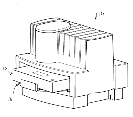
As best seen in FIGS. 7 and 8, adapter 10 of the present invention preferably is a
separate enclosed unit designed to be supported m~.h~nically a(lja~nt to surgical console
12. While any suitable surgical console 12 may be used, the SERIES TW~Y
THOUSAND~ LEGACY(E~) PHAC~EMtJLSIFIER~ surgical console, m~mlfactllred by
25 Alcon Laboratories, Inc., Fort Worth, Texas, is pl~r~ d. Other suitable consoles are
described in U.S. Patent Nos. 5,249,121 (Laurn, et al.), 5,268,624 (Zanger), 5,392,653
(Zanger, et al.) and 5,417,246 (Perkins, et al.), the entire contents of which are
incorporated herein by reference. Adapter 10 may be supported on console 12 by any
2~756~
suitable method, such as slide out bail 14 on console 12 interacting with bottom enclosure
47, which is secured to mounting bracket 24 on adapter 10.
As best seen in FIGS 1, 2, 3, 5 and 7, adapter 10 contains platform 16 that
receives external cassette 18. One suitable cassette 18 is described in U.S. Patent No.
s 4,713,051 (Steppe, et al.) (hereinafter the "Steppe" cassette), but other suitable c~settes
18, such as those described in the patents listed above, may also be used in co~l~in~lion
with the present invention by the ~ro~liate modifications to adapter 10.
Adapter 10 includes all of the m~h~nical and electrical components necessary to
allow cassette 18 to be used in combination with console 12. For example, as seen in
o FIGS. 5 and 6, if cassette 18 is of a peristaltic pump design (such as the Steppe cassette),
then adapter 10 may contain motor 20 that rotates peristaltic pump roller head 22. If
cassette 18 is of a diaphragm or venturi design, then adapter 10 may contain a diaphragm
pump (not shown) or a venturi pump (not shown). Other components of adapter 10 may
include irrigation solenoid 28, vent solenoid 30 and purge valve 32. Purge valve 32
communicates with cassette 18 through port 34 and allows monitoring of the aspiration
pressure within cassette 18. Irrigation solenoid 28 pinches the irrigation lines (not shown)
within cassette 18 to control the flow of irrigation fluid to the surgical site. Vent solenoid
30 pinches the vent line (not shown) within c~sette 18 to control the aspiration pressure
within cassette 18. A more complete discussion of the operation of Steppe-type cassettes
18 is contained in U.S. Patent No. 4,713,051.
While the above discussion relates to the use of a Steppe-type cassette 18, it will
be appreciated that other suitable mechanical and electrical controls may be used in
adapter 10. For example, adapter 10 may include the devices described in U.S Patent
Nos. 5,387,088 (Knapp, et al.), 5,328,456 (Horiguchi, et al.) and 5,230,614 (Zanger, et al.),
the entire contents of which are incorporated herein by reference.
Adapter 10 operates under the control of signals generated by PCB 42, which is
mounted on bracket 44 within adapter 10. PCB 42 pl~r~l~bly contains an INIEL(~) 80196,
but other suitable microprocessors may also be used. One suitable block diagram for PCB
42 is illustrated in FIG. 4.
As seen in FIGS. 3 and 4, communications, power and control signals are providedbetween adapter 10 and console 12 through a cable (not shown) conn~te~l to port 46 on
adapter 10. As a result, it is not necessary to duplicate in adapter 10 all of the control
6 0
circuitry, user int~f~ce controls and power supplies that are contained in console 12.
This description is given for purposes of illustration and explanation. It will be
a~ l to those skilled in the relevant art that ~ n~ and modifications may be made
to the invention described above without departing from its scope or spirit.