Language selection

Search

Patent 2187595 Summary

Third-party information liability

Some of the information on this Web page has been provided by external sources. The Government of Canada is not responsible for the accuracy, reliability or currency of the information supplied by external sources. Users wishing to rely upon this information should consult directly with the source of the information. Content provided by external sources is not subject to official languages, privacy and accessibility requirements.

Claims and Abstract availability

Any discrepancies in the text and image of the Claims and Abstract are due to differing posting times. Text of the Claims and Abstract are posted:

  • At the time the application is open to public inspection;
  • At the time of issue of the patent (grant).
(12) Patent: (11) CA 2187595
(54) English Title: ROLL DESIGN
(54) French Title: CONFIGURATION DE TAMBOUR
Status: Expired and beyond the Period of Reversal
Bibliographic Data
(51) International Patent Classification (IPC):
  • B30B 09/20 (2006.01)
  • F26B 13/28 (2006.01)
(72) Inventors :
  • SAALASTI, TIMO TAPIO (Finland)
(73) Owners :
  • FINBARK OY
(71) Applicants :
  • FINBARK OY (Finland)
(74) Agent: SMART & BIGGAR LP
(74) Associate agent:
(45) Issued: 2002-11-26
(22) Filed Date: 1996-10-10
(41) Open to Public Inspection: 1997-04-14
Examination requested: 1997-03-13
Availability of licence: N/A
Dedicated to the Public: N/A
(25) Language of filing: English

Patent Cooperation Treaty (PCT): No

(30) Application Priority Data:
Application No. Country/Territory Date
954892 (Finland) 1995-10-13

Abstracts

English Abstract

The invention relates to a drum press, in which the gap between the drum (1) andthe roll (2) is greater at the input end than at the output end. The gap may decrease continuously or stepwise. Most preferably the drum is cylindrical in shape and the front end of the roll is thinner than the rear end. The chief advantage of the device is that feeding is easier to arrange with more space at the input end. The device is applicable for instance in the pressing of bark, sludge or chemical pulp.


French Abstract

L'invention concerne une presse à tambour, dans laquelle l'espace entre le tambour (1) et le rouleau (2) est plus grand à l'extrémité d'entrée qu'à l'extrémité de sortie. L'espace peut diminuer de manière continue ou par étapes. De manière préférée entre toutes, le tambour est de forme cylindrique et l'extrémité avant du rouleau est plus mince que l'extrémité arrière. L'avantage essentiel de ce dispositif consiste en ce que l'alimentation est plus facile à agencer avec plus d'espace au niveau de l'extrémité d'entrée. Le dispositif peut être appliqué, par exemple, au pressage de l'écorce, de boues ou de pâte chimique.

Claims

Note: Claims are shown in the official language in which they were submitted.

4
CLAIMS:
1. A drum press comprising a drum with an input end
and an output end, and a press roll disposed inside the
drum, at least one of said drum and said press roll having
an axis and being rotatable thereabout, said drum and said
press roll defining a passage therebetween for receiving
material to be pressed, said passage extending continuously
from said input end to said output end wherein the space
between the drum and the press roll is greater at the input
end than at the output end.
2. A drum press as claimed in claim 1, in which the
roll has a smaller diameter at the input end than at the
output end.
3. A drum press as claimed in claim 1 or 2, in which
the drum is cylindrical.
4. A drum press as claimed in any one of claims 1 to
3, in which the roll is conical.
5. A drum press as claimed in any one of claims 1 to
3, in which the diameter of the roll increases stepwise from
the input end toward the output end.
6. A drum press as claimed in claim 1, in which the
distance of the roll from the drum is adjustable.
7. A drum press as claimed in claim 6, in which the
spacings between the drum and the press roll at said input
end and at said output end are adjustable independently of
each other.

5
8. A drum press as claimed in any one of claims 1 to 7,
wherein one of said drum and said press roll is positioned
eccentrically relative to the other of said drum and said press
roll.
9. Use of a drum press as claimed in any one of claims 1
to 8 for the pressing of bark, sludge or chemical pulp.
10. A method of pressing material in a drum press as
defined in any one of claims 1 to 8, comprising the step of
circulating the material around said drum to press said material
between said drum and said press roll several times.

Description

Note: Descriptions are shown in the official language in which they were submitted.


CA 02187595 1999-11-15
1
ROLL DESIGN
Technical Background
The invention relates to a drum press which is usable for
instance for pressing moist bark to make it suitable as a fuel.
The drum press has a rotating drum and inside this a prallel
eccentrically positioned press roll. As the drum rotates, the
material to be handled is pressed between the roll and the drum.
The material is usually fed at one end of the drum and removed
at the opposite end. The drum is usually perforated, so that
liquid may be discr.arged from the material to be pressed through
the drum mantle. for transferring the material, the drum or the
roll is usually inclined, or optionally deflectors inclined in
the material flow direction are provided inside the drum.
For example FI pate:nt specification 69207 discloses a drum press
operating according to the "multiple press method", in which
material circulates several times about the drum. The drum in
such a drum press usually has at least a length equal to its
diameter, or even longer. The roll diameter being great
relative to the drum diameter, there will be relatively little
space between the drum and the roll, and the feeding of
especially great material flows between the drum and the roll
will be awkward.
Description of the Invention
The chief purpose of the invention is to provide a drum press in
which the feeding c:an be arranged better than in known
solutions.
This purpose can be achieved by making the space between the
drum and the roll, i.e. the difference between the cross areas
of the drum and the roll, greater at the input end than at the

CA 02187595 2001-08-30
w
,; '66600-251
2
output end. The space may be continuously (e. g. linearly)
or stepwise decreasing. Most appropriately the drum is
cylindrical in shape and the front end of the roll is
narrower than the rear end.
According to the present invention there is
provided a drum press comprising a drum with an input end
and an output end, and a press roll disposed inside the
drum, at least one of said drum and said press roll having
an axis and being rotatable thereabout, said drum and said
press roll defining a passage therebetween for receiving
material to be pressed, said passage extending continuously
from said input end to said output end wherein the space
between the drum and the press roll is greater at the input
end than at the output end.
The main advantage of the invention is that the
feeding can be effectively carried out with great material
flows. Nevertheless, the material can be compressed into as
thin a mat as possible at the rear end of the drum, allowing
maximum dry-matter content to be achieved. Yet nor the size
nor the weight of the device need to be increased to achieve
these advantages.
The press in accordance with the invention can
primarily be used for dehydrating material containing water.
Pressing of bark, purification plant sludge, chemical pulp
or peat are typical objects of application.
A number of preferred embodiments of the invention
will be described in greater detail below with reference to
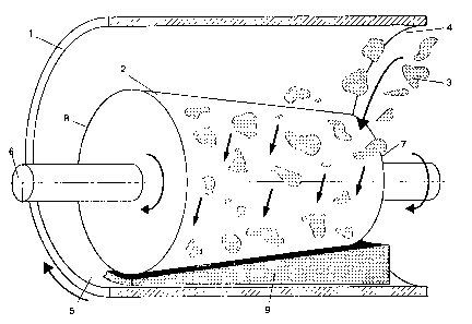
the accompanying drawings. In these, figure 1 shows a
lateral view of the drum press and figure 2 a lateral view
of a second drum press.

CA 02187595 2001-08-30
66600-251
2a
The main components of the press are a rotating
drum 1 and a press roll 2 rotating inside this. The drum is
perforated with holes, through which liquid is removed from
the material 3 to be squeezed. The roll can also be made
hollow and perforated, and then liquid is discharged also
through the roll. Material is introduced at the front end 4
of the drum. It circulates several times in the drum while
being compressed, and leaves the drum at rear end 5. The
drum can be used for instance for dehydrating moist bark.
The shaft or roll is mounted on bearings such that
the front end 7 and the rear end 8 of the roll can be lifted
and lowered independently of each other. Most preferably
the ends are mounted floatingly on bearings, for instance by
means of a hydraulic cylinder, so that the roll presses the
material under constant pressure regardless of the thickness
of the material layer. The roll 2 may be positioned
eccentrically within the drum, as shown in the figures.
The drum press can be devised such that either the
roll alone, or both the roll and the drum, or the drum
alone, are rotated. Power transmission can be accomplished
as desired. Techniques implemented in drum presses have
been described e.g. in patents FI 69207 and FI 90442.
Front end 7 of roll 2 has a diameter smaller than
the diameter of rear end 8 of the roll.
Roll 2 may initially be adjusted by means of a
stopper for instance in a position such that it does not
touch drum 1. As material 3 is first fed at the front end 4
of the

2187595
3
drum, it will lift the front end 7 of the roll as it gets between the drum and
the roll.
As the material proceeds, it will also lift the rear end 8 of the roll.
Between the
drum and the roll, the material flow will form a wedge-shaped mat of material
9,
which is removed at the rear end of the drum. The material progress can be
acted on
by means of the angle of inclination of the drum or with deflectors.
At the front end 4 of drum 1 there is plenty of space above the roll 2, which
facilitates the feeding arrangement. Moreover, the feeding procedure will be
reliable, given that even bulkier pieces of material will pass through the
large input
opening.
At the front end 4 of drum 1 there is plenty of space also below the roll, so
that mat
9 may have a relatively thick front end relative to its rear end. This allows
even a
great material flow to be compressed to a high dry-matter content. Despite
this, the
angle of inclination of the roll remains very close to its initial position,
which
facilitates pivoting arrangements. Nevertheless; the roll has relatively-large
play.
The supplementary space at the front end 4 of drum 1 also reduces wear;
because a
thick mat of e.g. sandy bark will not be in violent contact with the
components
above the roll. Wear of the feed device is also reduced, because the material
does
not have to be introduced in the drum with great force.
In the drum press illustrated in figure 2, roll 2' has a constant diameter at
front end
T, then the diameter grows stepwise at 10 and becomes constant again at rear
end 8'.
Thus, the thickness of material mat 9' also changes stepwise. When needed, the
number of steps may be greater. A stepwise varying gap between the drum and
the
roll is adequate in implementations where pressing is to be accomplished in
different steps under distinctly different pressures. An example of such an
implementation is pulp washing. A specific pulp washing process is described
e.g.
in FI patent specification 90442 (corresponding to PCT patent application
FI93/00452).
The invention can also be accomplished for instance such that the drum
diameter is
greater at the front end than at the rear end.

Representative Drawing
A single figure which represents the drawing illustrating the invention.
Administrative Status

2024-08-01:As part of the Next Generation Patents (NGP) transition, the Canadian Patents Database (CPD) now contains a more detailed Event History, which replicates the Event Log of our new back-office solution.

Please note that "Inactive:" events refers to events no longer in use in our new back-office solution.

For a clearer understanding of the status of the application/patent presented on this page, the site Disclaimer , as well as the definitions for Patent , Event History , Maintenance Fee  and Payment History  should be consulted.

Event History

Description Date
Time Limit for Reversal Expired 2016-10-11
Letter Sent 2015-10-13
Inactive: Office letter 2010-02-26
Inactive: Office letter 2010-02-24
Inactive: Reversal of will be deemed expired status 2009-12-04
Inactive: Payment - Insufficient fee 2009-12-04
Letter Sent 2009-10-13
Inactive: IPC from MCD 2006-03-12
Grant by Issuance 2002-11-26
Inactive: Cover page published 2002-11-25
Inactive: Final fee received 2002-08-28
Pre-grant 2002-08-28
Notice of Allowance is Issued 2002-03-12
Letter Sent 2002-03-12
Inactive: Approved for allowance (AFA) 2002-03-01
Amendment Received - Voluntary Amendment 2001-08-30
Inactive: S.30(2) Rules - Examiner requisition 2001-06-27
Amendment Received - Voluntary Amendment 2000-09-08
Inactive: S.30(2) Rules - Examiner requisition 2000-03-14
Amendment Received - Voluntary Amendment 1999-11-15
Inactive: S.30(2) Rules - Examiner requisition 1999-05-14
Inactive: Application prosecuted on TS as of Log entry date 1997-07-31
Inactive: Status info is complete as of Log entry date 1997-07-31
Application Published (Open to Public Inspection) 1997-04-14
Request for Examination Requirements Determined Compliant 1997-03-13
All Requirements for Examination Determined Compliant 1997-03-13

Abandonment History

There is no abandonment history.

Maintenance Fee

The last payment was received on 2002-09-17

Note : If the full payment has not been received on or before the date indicated, a further fee may be required which may be one of the following

  • the reinstatement fee;
  • the late payment fee; or
  • additional fee to reverse deemed expiry.

Patent fees are adjusted on the 1st of January every year. The amounts above are the current amounts if received by December 31 of the current year.
Please refer to the CIPO Patent Fees web page to see all current fee amounts.

Owners on Record

Note: Records showing the ownership history in alphabetical order.

Current Owners on Record
FINBARK OY
Past Owners on Record
TIMO TAPIO SAALASTI
Past Owners that do not appear in the "Owners on Record" listing will appear in other documentation within the application.
Documents

To view selected files, please enter reCAPTCHA code :


To view images, click a link in the Document Description column. To download the documents, select one or more checkboxes in the first column and then click the "Download Selected in PDF format (Zip Archive)" or the "Download Selected as Single PDF" button.

List of published and non-published patent-specific documents on the CPD .

If you have any difficulty accessing content, you can call the Client Service Centre at 1-866-997-1936 or send them an e-mail at CIPO Client Service Centre.


Document
Description 
Date
(yyyy-mm-dd) 
Number of pages   Size of Image (KB) 
Description 2001-08-29 4 178
Claims 2001-08-29 2 47
Representative drawing 2002-02-28 1 24
Abstract 1997-03-03 1 14
Description 1997-03-03 3 168
Drawings 1997-03-03 2 78
Claims 1997-03-03 1 31
Description 2000-09-07 4 182
Claims 2000-09-07 2 50
Claims 1999-11-14 2 53
Description 1999-11-14 4 181
Representative drawing 1997-08-26 1 34
Reminder of maintenance fee due 1998-06-10 1 111
Commissioner's Notice - Application Found Allowable 2002-03-11 1 166
Notice of Insufficient fee payment (English) 2009-12-03 1 91
Maintenance Fee Notice 2015-11-23 1 170
Correspondence 2002-08-27 1 35
Fees 1999-09-12 1 40
Fees 2009-09-23 1 40
Correspondence 2009-12-03 1 24
Correspondence 2010-02-23 2 33
Correspondence 2010-02-25 1 13