Sélection de la langue

Search

Sommaire du brevet 2187595 

Énoncé de désistement de responsabilité concernant l'information provenant de tiers

Une partie des informations de ce site Web a été fournie par des sources externes. Le gouvernement du Canada n'assume aucune responsabilité concernant la précision, l'actualité ou la fiabilité des informations fournies par les sources externes. Les utilisateurs qui désirent employer cette information devraient consulter directement la source des informations. Le contenu fourni par les sources externes n'est pas assujetti aux exigences sur les langues officielles, la protection des renseignements personnels et l'accessibilité.

Disponibilité de l'Abrégé et des Revendications

L'apparition de différences dans le texte et l'image des Revendications et de l'Abrégé dépend du moment auquel le document est publié. Les textes des Revendications et de l'Abrégé sont affichés :

  • lorsque la demande peut être examinée par le public;
  • lorsque le brevet est émis (délivrance).
(12) Brevet: (11) CA 2187595
(54) Titre français: CONFIGURATION DE TAMBOUR
(54) Titre anglais: ROLL DESIGN
Statut: Périmé et au-delà du délai pour l’annulation
Données bibliographiques
(51) Classification internationale des brevets (CIB):
  • B30B 09/20 (2006.01)
  • F26B 13/28 (2006.01)
(72) Inventeurs :
  • SAALASTI, TIMO TAPIO (Finlande)
(73) Titulaires :
  • FINBARK OY
(71) Demandeurs :
  • FINBARK OY (Finlande)
(74) Agent: SMART & BIGGAR LP
(74) Co-agent:
(45) Délivré: 2002-11-26
(22) Date de dépôt: 1996-10-10
(41) Mise à la disponibilité du public: 1997-04-14
Requête d'examen: 1997-03-13
Licence disponible: S.O.
Cédé au domaine public: S.O.
(25) Langue des documents déposés: Anglais

Traité de coopération en matière de brevets (PCT): Non

(30) Données de priorité de la demande:
Numéro de la demande Pays / territoire Date
954892 (Finlande) 1995-10-13

Abrégés

Abrégé français

L'invention concerne une presse à tambour, dans laquelle l'espace entre le tambour (1) et le rouleau (2) est plus grand à l'extrémité d'entrée qu'à l'extrémité de sortie. L'espace peut diminuer de manière continue ou par étapes. De manière préférée entre toutes, le tambour est de forme cylindrique et l'extrémité avant du rouleau est plus mince que l'extrémité arrière. L'avantage essentiel de ce dispositif consiste en ce que l'alimentation est plus facile à agencer avec plus d'espace au niveau de l'extrémité d'entrée. Le dispositif peut être appliqué, par exemple, au pressage de l'écorce, de boues ou de pâte chimique.


Abrégé anglais

The invention relates to a drum press, in which the gap between the drum (1) andthe roll (2) is greater at the input end than at the output end. The gap may decrease continuously or stepwise. Most preferably the drum is cylindrical in shape and the front end of the roll is thinner than the rear end. The chief advantage of the device is that feeding is easier to arrange with more space at the input end. The device is applicable for instance in the pressing of bark, sludge or chemical pulp.

Revendications

Note : Les revendications sont présentées dans la langue officielle dans laquelle elles ont été soumises.


4
CLAIMS:
1. A drum press comprising a drum with an input end
and an output end, and a press roll disposed inside the
drum, at least one of said drum and said press roll having
an axis and being rotatable thereabout, said drum and said
press roll defining a passage therebetween for receiving
material to be pressed, said passage extending continuously
from said input end to said output end wherein the space
between the drum and the press roll is greater at the input
end than at the output end.
2. A drum press as claimed in claim 1, in which the
roll has a smaller diameter at the input end than at the
output end.
3. A drum press as claimed in claim 1 or 2, in which
the drum is cylindrical.
4. A drum press as claimed in any one of claims 1 to
3, in which the roll is conical.
5. A drum press as claimed in any one of claims 1 to
3, in which the diameter of the roll increases stepwise from
the input end toward the output end.
6. A drum press as claimed in claim 1, in which the
distance of the roll from the drum is adjustable.
7. A drum press as claimed in claim 6, in which the
spacings between the drum and the press roll at said input
end and at said output end are adjustable independently of
each other.

5
8. A drum press as claimed in any one of claims 1 to 7,
wherein one of said drum and said press roll is positioned
eccentrically relative to the other of said drum and said press
roll.
9. Use of a drum press as claimed in any one of claims 1
to 8 for the pressing of bark, sludge or chemical pulp.
10. A method of pressing material in a drum press as
defined in any one of claims 1 to 8, comprising the step of
circulating the material around said drum to press said material
between said drum and said press roll several times.

Description

Note : Les descriptions sont présentées dans la langue officielle dans laquelle elles ont été soumises.

CA 02187595 1999-11-15
1
ROLL DESIGN
Technical Background
The invention relates to a drum press which is usable for
instance for pressing moist bark to make it suitable as a fuel.
The drum press has a rotating drum and inside this a prallel
eccentrically positioned press roll. As the drum rotates, the
material to be handled is pressed between the roll and the drum.
The material is usually fed at one end of the drum and removed
at the opposite end. The drum is usually perforated, so that
liquid may be discr.arged from the material to be pressed through
the drum mantle. for transferring the material, the drum or the
roll is usually inclined, or optionally deflectors inclined in
the material flow direction are provided inside the drum.
For example FI pate:nt specification 69207 discloses a drum press
operating according to the "multiple press method", in which
material circulates several times about the drum. The drum in
such a drum press usually has at least a length equal to its
diameter, or even longer. The roll diameter being great
relative to the drum diameter, there will be relatively little
space between the drum and the roll, and the feeding of
especially great material flows between the drum and the roll
will be awkward.
Description of the Invention
The chief purpose of the invention is to provide a drum press in
which the feeding c:an be arranged better than in known
solutions.
This purpose can be achieved by making the space between the
drum and the roll, i.e. the difference between the cross areas
of the drum and the roll, greater at the input end than at the

CA 02187595 2001-08-30
w
,; '66600-251
2
output end. The space may be continuously (e. g. linearly)
or stepwise decreasing. Most appropriately the drum is
cylindrical in shape and the front end of the roll is
narrower than the rear end.
According to the present invention there is
provided a drum press comprising a drum with an input end
and an output end, and a press roll disposed inside the
drum, at least one of said drum and said press roll having
an axis and being rotatable thereabout, said drum and said
press roll defining a passage therebetween for receiving
material to be pressed, said passage extending continuously
from said input end to said output end wherein the space
between the drum and the press roll is greater at the input
end than at the output end.
The main advantage of the invention is that the
feeding can be effectively carried out with great material
flows. Nevertheless, the material can be compressed into as
thin a mat as possible at the rear end of the drum, allowing
maximum dry-matter content to be achieved. Yet nor the size
nor the weight of the device need to be increased to achieve
these advantages.
The press in accordance with the invention can
primarily be used for dehydrating material containing water.
Pressing of bark, purification plant sludge, chemical pulp
or peat are typical objects of application.
A number of preferred embodiments of the invention
will be described in greater detail below with reference to
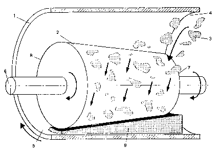
the accompanying drawings. In these, figure 1 shows a
lateral view of the drum press and figure 2 a lateral view
of a second drum press.

CA 02187595 2001-08-30
66600-251
2a
The main components of the press are a rotating
drum 1 and a press roll 2 rotating inside this. The drum is
perforated with holes, through which liquid is removed from
the material 3 to be squeezed. The roll can also be made
hollow and perforated, and then liquid is discharged also
through the roll. Material is introduced at the front end 4
of the drum. It circulates several times in the drum while
being compressed, and leaves the drum at rear end 5. The
drum can be used for instance for dehydrating moist bark.
The shaft or roll is mounted on bearings such that
the front end 7 and the rear end 8 of the roll can be lifted
and lowered independently of each other. Most preferably
the ends are mounted floatingly on bearings, for instance by
means of a hydraulic cylinder, so that the roll presses the
material under constant pressure regardless of the thickness
of the material layer. The roll 2 may be positioned
eccentrically within the drum, as shown in the figures.
The drum press can be devised such that either the
roll alone, or both the roll and the drum, or the drum
alone, are rotated. Power transmission can be accomplished
as desired. Techniques implemented in drum presses have
been described e.g. in patents FI 69207 and FI 90442.
Front end 7 of roll 2 has a diameter smaller than
the diameter of rear end 8 of the roll.
Roll 2 may initially be adjusted by means of a
stopper for instance in a position such that it does not
touch drum 1. As material 3 is first fed at the front end 4
of the

2187595
3
drum, it will lift the front end 7 of the roll as it gets between the drum and
the roll.
As the material proceeds, it will also lift the rear end 8 of the roll.
Between the
drum and the roll, the material flow will form a wedge-shaped mat of material
9,
which is removed at the rear end of the drum. The material progress can be
acted on
by means of the angle of inclination of the drum or with deflectors.
At the front end 4 of drum 1 there is plenty of space above the roll 2, which
facilitates the feeding arrangement. Moreover, the feeding procedure will be
reliable, given that even bulkier pieces of material will pass through the
large input
opening.
At the front end 4 of drum 1 there is plenty of space also below the roll, so
that mat
9 may have a relatively thick front end relative to its rear end. This allows
even a
great material flow to be compressed to a high dry-matter content. Despite
this, the
angle of inclination of the roll remains very close to its initial position,
which
facilitates pivoting arrangements. Nevertheless; the roll has relatively-large
play.
The supplementary space at the front end 4 of drum 1 also reduces wear;
because a
thick mat of e.g. sandy bark will not be in violent contact with the
components
above the roll. Wear of the feed device is also reduced, because the material
does
not have to be introduced in the drum with great force.
In the drum press illustrated in figure 2, roll 2' has a constant diameter at
front end
T, then the diameter grows stepwise at 10 and becomes constant again at rear
end 8'.
Thus, the thickness of material mat 9' also changes stepwise. When needed, the
number of steps may be greater. A stepwise varying gap between the drum and
the
roll is adequate in implementations where pressing is to be accomplished in
different steps under distinctly different pressures. An example of such an
implementation is pulp washing. A specific pulp washing process is described
e.g.
in FI patent specification 90442 (corresponding to PCT patent application
FI93/00452).
The invention can also be accomplished for instance such that the drum
diameter is
greater at the front end than at the rear end.

Dessin représentatif
Une figure unique qui représente un dessin illustrant l'invention.
États administratifs

2024-08-01 : Dans le cadre de la transition vers les Brevets de nouvelle génération (BNG), la base de données sur les brevets canadiens (BDBC) contient désormais un Historique d'événement plus détaillé, qui reproduit le Journal des événements de notre nouvelle solution interne.

Veuillez noter que les événements débutant par « Inactive : » se réfèrent à des événements qui ne sont plus utilisés dans notre nouvelle solution interne.

Pour une meilleure compréhension de l'état de la demande ou brevet qui figure sur cette page, la rubrique Mise en garde , et les descriptions de Brevet , Historique d'événement , Taxes périodiques et Historique des paiements devraient être consultées.

Historique d'événement

Description Date
Le délai pour l'annulation est expiré 2016-10-11
Lettre envoyée 2015-10-13
Inactive : Lettre officielle 2010-02-26
Inactive : Lettre officielle 2010-02-24
Inactive : Renversement de l'état sera réputé périmé 2009-12-04
Inactive : Paiement - Taxe insuffisante 2009-12-04
Lettre envoyée 2009-10-13
Inactive : CIB de MCD 2006-03-12
Accordé par délivrance 2002-11-26
Inactive : Page couverture publiée 2002-11-25
Inactive : Taxe finale reçue 2002-08-28
Préoctroi 2002-08-28
Un avis d'acceptation est envoyé 2002-03-12
Lettre envoyée 2002-03-12
Inactive : Approuvée aux fins d'acceptation (AFA) 2002-03-01
Modification reçue - modification volontaire 2001-08-30
Inactive : Dem. de l'examinateur par.30(2) Règles 2001-06-27
Modification reçue - modification volontaire 2000-09-08
Inactive : Dem. de l'examinateur par.30(2) Règles 2000-03-14
Modification reçue - modification volontaire 1999-11-15
Inactive : Dem. de l'examinateur par.30(2) Règles 1999-05-14
Inactive : Dem. traitée sur TS dès date d'ent. journal 1997-07-31
Inactive : Renseign. sur l'état - Complets dès date d'ent. journ. 1997-07-31
Demande publiée (accessible au public) 1997-04-14
Exigences pour une requête d'examen - jugée conforme 1997-03-13
Toutes les exigences pour l'examen - jugée conforme 1997-03-13

Historique d'abandonnement

Il n'y a pas d'historique d'abandonnement

Taxes périodiques

Le dernier paiement a été reçu le 2002-09-17

Avis : Si le paiement en totalité n'a pas été reçu au plus tard à la date indiquée, une taxe supplémentaire peut être imposée, soit une des taxes suivantes :

  • taxe de rétablissement ;
  • taxe pour paiement en souffrance ; ou
  • taxe additionnelle pour le renversement d'une péremption réputée.

Les taxes sur les brevets sont ajustées au 1er janvier de chaque année. Les montants ci-dessus sont les montants actuels s'ils sont reçus au plus tard le 31 décembre de l'année en cours.
Veuillez vous référer à la page web des taxes sur les brevets de l'OPIC pour voir tous les montants actuels des taxes.

Titulaires au dossier

Les titulaires actuels et antérieures au dossier sont affichés en ordre alphabétique.

Titulaires actuels au dossier
FINBARK OY
Titulaires antérieures au dossier
TIMO TAPIO SAALASTI
Les propriétaires antérieurs qui ne figurent pas dans la liste des « Propriétaires au dossier » apparaîtront dans d'autres documents au dossier.
Documents

Pour visionner les fichiers sélectionnés, entrer le code reCAPTCHA :


Pour visualiser une image, cliquer sur un lien dans la colonne description du document. Pour télécharger l'image (les images), cliquer l'une ou plusieurs cases à cocher dans la première colonne et ensuite cliquer sur le bouton "Télécharger sélection en format PDF (archive Zip)" ou le bouton "Télécharger sélection (en un fichier PDF fusionné)".

Liste des documents de brevet publiés et non publiés sur la BDBC .

Si vous avez des difficultés à accéder au contenu, veuillez communiquer avec le Centre de services à la clientèle au 1-866-997-1936, ou envoyer un courriel au Centre de service à la clientèle de l'OPIC.


Description du
Document 
Date
(aaaa-mm-jj) 
Nombre de pages   Taille de l'image (Ko) 
Description 2001-08-29 4 178
Revendications 2001-08-29 2 47
Dessin représentatif 2002-02-28 1 24
Abrégé 1997-03-03 1 14
Description 1997-03-03 3 168
Dessins 1997-03-03 2 78
Revendications 1997-03-03 1 31
Description 2000-09-07 4 182
Revendications 2000-09-07 2 50
Revendications 1999-11-14 2 53
Description 1999-11-14 4 181
Dessin représentatif 1997-08-26 1 34
Rappel de taxe de maintien due 1998-06-10 1 111
Avis du commissaire - Demande jugée acceptable 2002-03-11 1 166
Avis de paiement insuffisant pour taxe (anglais) 2009-12-03 1 91
Avis concernant la taxe de maintien 2015-11-23 1 170
Correspondance 2002-08-27 1 35
Taxes 1999-09-12 1 40
Taxes 2009-09-23 1 40
Correspondance 2009-12-03 1 24
Correspondance 2010-02-23 2 33
Correspondance 2010-02-25 1 13