Note: Descriptions are shown in the official language in which they were submitted.
'187712
PATENT APPLICATION
1750 (203-1573)
APPARATUS AND METHOD FOR REMOVING TISSUE
BACKGROUND
1. Technical Field
The present disclosure relates to apparatus and
method for removal of tissue from within a patient's body.
More particularly, the present disclosure relates to
apparatus and method for percutaneous tissue removal.
2. Description of the Related Art
Numerous surgical instruments have been developed
for performing minimally invasive surgical procedures.
Such procedures greatly reduce recovery time for the
patients in comparison to conventional open surgical
procedures. Minimally invasive instruments also minimize
damage to tissue surrounding the operative site. The
enormous success of such instruments in procedures such as
gall bladder removal and hernia repair has led to increased
development of minimally invasive instruments for other
operative procedures as well.
One area where minimally invasive instruments
have begun to be utilized is in performing biopsies of
suspect breast tissue to determine whether the tissue is
malignant or benign. As is quite often the case, lesions
within the breast are non-palpable, therefore, early
diagnosis of suspect lesions in a patient's breast, which
may be cancerous, has been greatly enhanced through the
development of imaging machines, for example, stereotactic
CA 02187712 2004-12-24
2
mammography imaging systems (hereafter referred to as
"stereotactic machines"). In such machines, an elongated
prone supporting examining table for x-ray mammography is
provided with a central breast receiving aperture, through
which the patient's pendulant breast is exposed to a
horizontal beam of x-rays from a source which is angularly
movable through an arc centered on the patient's breast
permitting x-ray projection through more than 360 degrees
around the patient's body. An example of such a
stereotactic machine is disclosed in 1I.S. Patent No.
5,289,520 which issued on February 22, 1994 to Pellegrino
et aI.
Fine needle biopsy is also facilitated by
stereotactic machines. In such procedures, doctors can
take advantage of the precision instrument positioning and
suspect tissue position locating capax>ilit:ies of the
machine's imaging systems, to precisely insert a biopsy
needle and retrieve a tissue sample.
However, minimally invasive instrumentation to
remove target tissue to avoid open surgical techniques or
potentially even mastectomy is not readily available. The
present disclosure provides minimally invasive apparatus
which are relatively easy to use and are inexpensive to
manufacture and assemble. The present disclosure also
provides methods for removing target tissue using such
minimally invasive instrumentation.
w.. .. .x_ .. r. ~..~r wr,. ~~~ .w~~.,,.m~,...w~:,~ ~~~~,~
._~.ay~a~~.~~.~~~~~~.A~..
21 X7712
3
SUMMARY
The present disclosure provides a surgical
instrument for cutting tissue, which includes a housing, a
cutting element movable between a retracted position
disposed substantially within the housing and a deployed
position extending outwardly from the housing, a guide
member configured and dimensioned to direct orientation of
the cutting element, operatively connected to the housing
and defining a longitudinal axis, the guide member movable
from a first orientation wherein the longitudinal axis of
the guide member is aligned with a longitudinal axis of the
housing to a second orientation wherein the longitudinal
axis of the guide member is oriented at a predetermined
angle relative to the longitudinal axis of the housing.
In a preferred embodiment the cutting element is
arcuately shaped. Alternatively and/or additionally, the
cutting element may be a composite of a plurality of
individual elements joined together. Also the instrument
may include a plurality of cutting elements and a plurality
of guide members. In such an embodiment, the plurality of
guide members are preferably pivotably deployable. A
cutting surface is preferably formed on at least one edge
of the blade.
The instrument may also include a tissue
retaining member positioned adjacent the guide member. In
a preferred embodiment, the tissue retaining member is
helically shaped such that upon rotation the tissue
retaining element spirals through tissue which it contacts.
CA 02187712 2004-12-24
4
The tissue retaining member may be fixedly mounted relative to
the housing. Alternatively, the tissue retaining member may
include a pair of graspers or like structure.
Another feature which may be provided on the
instrument is an actuator operatively connected to the guide
member and movable from a first position to a second position
to selectively effect movement of the guide member from the
first orientation to the second orientation. The actuator may
be rotatably mounted relative to the housing.
A separate actuator may be provided which is
operatively connected to the cutting element and movable from
a first position to a second position to selectively effect
movement of the cutting element from the retracted position to
the deployed position, This actuator ma.y be slidably mounted
relative to the housing.
In accordance with one embodiment of the present
invention there is provided a surgical instrument for cutting
tissue. The instrument includes a handle portion and a cutting
element operatively associated with the handle portion and
movable between a retracted position and a deployed position.
A guide member is configured and dimensioned to direct
orientation of the cutting element and is operatively
associated with the handle portion and defines a longitudinal
axis. The guide member is movable from a. first position
wherein the longitudinal axis of the guide member is aligned
with a longitudinal axis of the handle portion to a second
position wherein the longitudinal axis of the guide member is-
oriented at a predetermined angle relative to the longitudinal
axis of the housing. A tissue retaining member is positioned
adjacent the guide member and adapted to engage tissue such
that the tissue is retained adjacent the guide member.
In accordance with another embodiment of the present
invention the surgical instrument has a housing and a cutting
blade movable between a retracted position disposed
CA 02187712 2004-12-24
4a
substantially within the housing wherein t:he cutting blade
assumes a first configuration and a deployed position extending
outwardly from the housing wherein the cutting blade assumes
a,second configuration different from the first configuration.
A guide member is configured and dimensioned to direct
orientation of the cutting blade and is operatively connected
to the housing and defines a longitudinal axis. The guide
member is movable from a first orientation wherein the
longitudinal axis of the guide member is aligned with a
longitudinal axis of the housing to a second orientation
wherein the longitudinal axis of the guide member is oriented
at a predetermined angle relative to the longitudinal axis of
the housing.
In accordance with a further embodiment of the
present invention there is provided a su.rgi.cal instrument for
cutting tissue where the surgical instrument has a housing and
a plurality of cutting elements movable between a retracted
position disposed substantially within the housing and a
deployed position extending outwardly from the housing. A
plurality of guide members are configured and dimensioned to
direct orientation of the plurality of cutting elements. The
guide members are operatively connected to the housing and
define a longitudinal axis. The plurality of guide members are
movable from a first orientation wherein the longitudinal axis
of at least one of the plurality of guide members is aligned
with a longitudinal axis of the housing, to a second
orientation wherein the longitudinal axis of the at least one
guide member is oriented at a predetermined angle relative to
the longitudinal axis of the housing.
In accordance with a yet further embodiment of the
present invention there is provided a surgical instrument for
cutting tissue where the instrument has a handle portion and
a cutting blade operatively associated with the handle portion
and movable between a retracted position wherein the cutting
_. ... . e.r . * , . ..... _ Qe 2H..:~Ok:~ /uirv~~~M v .,YShPn e..:Apiit~,f
~5~~' ~t.~&R' ~a~Nkt ...-3=N'~ y~,R&~3.~ts~_-~--~~ ~a«.~,.- . . . . - ?~- .
CA 02187712 2004-12-24
4b
blade assumes a first configuration and a deployed position
wherein the cutting blade assumes a second configuration
different from the first configuration. A guide member is
configured and dimensioned to direct orientation of the cutting
blade and is operatively associated with the handle portion and
defines a longitudinal axis. The guide member is movable from
a first position wherein the longitudinal axis of the guide
member is aligned with a longitudinal axis of the handle
portion to a second position wherein the longitudinal axis of
the guide member is oriented at a predetermined angle relative
to the longitudinal axis of the housing. A tissue retaining
member is positioned adjacent the guide member and is adapted
to engage tissue such that the tissue is retained adjacent the
guide member.
In accordance with a further embodiment, the
surgical instrument has a handle portion and a plurality of
cutting elements operatively associated with the handle portion
and movable between a retracted position and a deployed
position. A plurality of guide members are provided, the
guide members being configured and dimensioned to direct
orientation of the plurality of cutting elements. The guide
members are operatively associated with the handle portion and
define a longitudinal axis. At least one of the plurality of
guide members is movable from a first position wherein the
longitudinal axis of the at least one guide member is aligned
with a longitudinal axis of the housing to a second position
wherein the longitudinal axis of the at least one guide member
is oriented at a predetermined angle relative to the
longitudinal axis of the housing. A tissue retaining member
is positioned adjacent the plurality of guide members and is
adapted to engage tissue such that the tissue is retained
adjacent the guide member.
In accordance with another embodiment of the present
invention there is provided a surgical instrument for cutting
v., "x.~..zi5r BAH,~$d.o,yh~ d'.sR~4-~~ww'.iiT~7;~2R"MeYq4isL,
Y=.~~~y~~tp~pb~539°OY 'W~siw,~99tF4~:7t~441Rb'1r~-'tt'trfi~w e...
,.Wtyypq,J s~s~3; ..,~>"~.
M. ~:A#,~~nmn~sem wu~. mwr. ... ~..H.,.ra.....,n."
CA 02187712 2004-12-24
4c
tissue where the surgical instrument includes a housing and a
cutting element movable between a retracted position disposed
substantially within the housing and a deployed position
extending outwardly from the housing. A guide member has a
passageway therethrough to direct orientation of the cutting
element through the passageway: The guide member is operatively
connected to the housing and defines a longitudinal axis. The
guide member is movable from a first orientation wherein the
longitudinal axis of the guide member is aligned with a
longitudinal axis of the housing to a second orientation
wherein the longitudinal axis of the guide member is oriented
at a predetermined angle relative to the longitudinal axis of
the housing.
In accordance with a further embodiment of the
present invention there is provided a surgical instrument for
cutting tissue, which comprises: a housing and a flexible
cutting blade movable between a retracted position wherein the
flexible cutting blade assumes a first configuration disposed
substantially within the housing and a deployed position
wherein the flexible cutting blade assumes a second
configuration extending outwardly from the housing. A guide
member is provided, the guide member being configured and
dimensioned to direct orientation of the cutting edge,
operatively connected to the housing and defining a
longitudinal axis. The guide member is movable from a first
orientation wherein the longitudinal axis of the guide member
is aligned with a longitudinal axis of the housing to a second
orientation wherein the longitudinal axis of the guide member
is oriented at a predetermined angle relative to the
longitudinal axis of the housing.
In accordance with a yet further embodiment of the
present invention there is provided a surgical instrument for
cutting tissue. The instrument has a housing and a flexible
cutting blade movable between a retracted position disposed
_... . ,... _..,, ..,. . r n t3, P."r..Lt1"e~.FS~ShR_3riFAau k;de~e~Ck37k4<sr
> N7tR .,VAA. si(MiF,,,v%1'..;TWJ'nCCn:5. ayy, ._..w, ~..."_
_.._....._._.._..~...____._.~ .._.... ..-
X#0 "w~W~73mt~~y .315u? ~W . : ;AnR~~>txonP°~~ ~T~.. -.
CA 02187712 2004-12-24
4d
substantially within the housing along an arcuate path wherein
the cutting blade assumes a second configuration different from
the first configuration and a deployed position extending
outwardly from the housing. The cutting blade defines a cutting
edge formed along at least one side thereof and is rotatable
about a central longitudinal axis of the surgical instrument.
A guide member is configured and dimensioned to direct
orientation of the cutting element and is operatively connected
to the housing and defines a longitudinal axis. The guide
member is movable from a first orientation wherein the
longitudinal axis of the guide member is aligned with a
longitudinal axis of. the housing to a second orientation
wherein the longitudinal axis of the guide member is oriented
at a predetermined angle relative to the longitudinal axis of
the housing.
In accordance with a still further embodiment of the
present invention there is provided a surgical instrument for
cutting tissue, which includes a housing and a guide member
fixedly connected to a distal end of the housing and having a
passageway therethrough and having a longitudinal axis. A
portion of the guide member is movable from a first orientation
wherein the longitudinal axis of the guide member is aligned
with a longitudinal axis of the housing to a second orientation
wherein the longitudinal axis of the guide member is oriented
at a predetermined angle relative to the longitudinal axis of
the housing. An elongated cutting blade is slidable through
the passageway of the guide member between a .retracted position.
disposed substantially within the housing and a deployed
position extending outwardly from the housing. The housing
includes an actuator actuable to move the elongated cutting
blade between the retracted and deployed positions.
A method for surgically removing tissue is also
provided and includes the steps of inserting an instrument into
an incision formed at the operative site, deploying a blade
scp; .~~y,.pv ,u: .>44 ,'~';:°w~..~~p,"-
.°~yi:~":,~»t!øit~p'Ra~e: ,. ..~.~..»f.v..v.
CA 02187712 2004-12-24
4e
guide at an angle relative to a longitudinal axis of the
instrument, deploying a cutting element from a retracted
position to an exposed position such that the cutting element
is guided by the blade guide, moving the cutting element
through a predetermined path such that a section of tissue is
separated from the surrounding tissue, and removing the cut
tissue from the surrounding tissue.
20
_ ~~811~,~
BRIEF DESCRIPTION OF THE DRAWINGS
Various embodiments are described herein with
reference to the drawings, wherein:
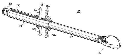
FIG. 1 is a perspective view of one embodiment of
5 the tissue removing instrument of the present disclosure;
FIG. 2 is a perspective view with parts separated
of the embodiment of FIG. 1;
FIG. 3 is a perspective view with parts separated
of the cutting blade subassembly
FIG. 4 is a cross-section view taken along
section line 4-4 of FIG. 3;
FIG. 5 is a cross-section view taken along
section line 5-5 of FIG. 3;
FIG. 6 is a perspective view with parts separated
of the composite blade assembly of the embodiment of FIG.
1;
FIG. 7 is a side view of the composite blade
assembly;
FIG. 8 is an enlarged view of the indicated area
of detail of FIG. 7;
FIG. 9 is a perspective view of the composite
cutting blade assembly;
FIG. 10 is a perspective view of the distal end
of the cutting blade guide assembly;
FIG. 11 is a perspective view with parts
separated of the cutting blade guide actuator;
FIG. 12 is a partial cross-section view taken
along section line 12-12 of FIG. 11;
2181712
6
FIG. 13 is a perspective view of the tissue
removing instrument being introduced into a patient;
FIG. 14 is a side view of the tissue removing
instrument in an initial configuration;
FIG. 15 is a cross-section view taken along
section line 15-15 of FIG. 14;
FIG. 16 is an enlarged view of the indicated area
of detail in FIG. 15;
FIG. 17 is a further perspective view of the
instrumentation in use illustrating deployment of the blade
guides;
FIG. 18 is a side view of the instrument
illustrating deployment of the blades' guides;
FIG. 19 is a cross-section view taken along
section line 19-19 of FIG. 18;
FIG. 20 is an enlarged view of the indicated area
of detail shown in FIG. 19;
FIG. 21 is a further perspective~view of the
instrument in use illustrating deployment of the cutting
blades of the tissue removing instrument;
FIG. 22 is a view similar to FIG. 18, which shows
deployment of the cutting blades;
FIG. 23 is a cross-section view taken along
section line 23-23 of FIG. 22;
FIG. 24 is an enlarged view of the indicated area
of detail shown in FIG. 23;
z~ $~~~z
FIG. 25 is a further perspective view of the
instrument in use illustrating rotational cutting of the
blades; and
FIG. 26 is an enlarged view of the distal end of
the instrument with the severed tissue contained therein.
DETAILED DESCRIPTION OF THE PREFERRED EMBODIMENTS
Referring initially to FIGS. 1 and 2, one
embodiment of an instrument for removing target tissue in
accordance with the present disclosure is designated by
reference numeral 100 throughout several views. Instrument
100 is particularly adapted for minimally invasive
insertion into tissue immediately adjacent target tissue,
isolating the target tissue from the surrounding tissue,
cutting the tissue and removing the tissue from the
patient. It will be understood by those skilled in the
art, however, that the embodiments of the tissue removing
instrument described herein, although directed to removal
of breast tissue, may also be utilized for removing
targeted tissue from other areas of a patient's body as
well.
Generally, instrument 100 includes a housing or
handle portion 110, an elongated tubular body portion 112
and a cutting head assembly 114. Except where noted
otherwise, the materials utilized in the components of the
instrument generally include such materials as
polycarbonate for housing sections and related components,
and stainless steel for components which transmit forces.
2181712
8
One preferred polycarbonate material is available from
General Electric under the trademark LEXAN. Radiolucent
materials are also preferably utilized, as appropriate, for
components which will be adjacent the target tissue so as
not to interfere with imaging.
Handle 110 is formed from handle half-sections
116 and 118 which are preferably molded to have
predetermined contoured regions for housing the various
components of instrument 100 as well as facilitating the
instrument's operation. Handle half-sections may be joined
by any suitable techniques,_such as snap fit connection,
bonding, ultrasonic welding or by suitable adhesives. Grip
portions 120 and 122 are provided on handle half-sections
116 and 118, respectively. Grip portions 120 and 122
preferably extend transversely away from a longitudinal
axis of instrument 100 and are preferably contoured to be
gripped by a single finger of the user. Handle half-
sections 116 and 118 are provided with cut-out regions 126
and 128, respectively, so as to define elongated
longitudinal slot 130 when the handle half-sections are
joined.
Elongated tubular portion 112 is secured between
the distal ends of handle half-sections 116 and 118,
preferably by bores 132 formed on the inner wall portions
of handle half-sections 116 and 118 being inserted in bores
134 formed near the proximal end of elongated tubular
member 112. A blade guide assembly 136 is provided and is
a subassembly of cutting head assembly 114. Blade guide
2187~i ~
9
assembly 136 is secured to the distal end of elongated
tubular member 112, for example by flexible finger portions
138 having lip portions 140 which engage slots 142 formed
near the distal end of elongated tubular member 112.
A cutting blade subassembly 144, which makes up a
second subassembly of cutting head assembly 114, is
slidably positioned within elongated tubular member 112.
Actuator 146 is rotatably disposed within a longitudinal
passageway formed in cutting blade assembly 144 as will be
described further herein.
Referring now to FIG. 2 in conjunction with FIGS.
3-5, cutting blade assembly 144 is preferably provided with
a grip 148 at the proximal end which includes contoured
portions 149 to facilitate a positive gripping by the user
upon actuation of instrument 100. A shaft 150 extends from
grip 148 and, as noted above, preferably forms a
longitudinal passageway 152 extending therethrough to
receive actuator 146. Shaft 150 is preferably formed of a
series of monolithically formed U-shaped longitudinal
channel sections 154 and is provided with raised guide
portions 156 and guide rails 158 to maintain the centrally
disposed position of shaft 150 within elongated tubular
member 112. This stabilization of shaft 150 is
particularly important during reciprocating sliding
movement of shaft 150 within elongated tubular member 112.
A series of blades 160 are preferably preformed to have a
predetermined curved configuration. Preferably the blades
are made from either all stainless steel or a composite of
218771
stainless steel and a shape memory alloy. In the
embodiment illustrated in FIG. 3, three such blades are
provided and are secured to the base portion 162, for
example by pins 166 being inserted through mounting holes
5 formed on base 162 and passing through mounting holes 168
formed near the proximal ends of blades 160.
Referring to FIGS. 6-9, blades 160 are preferably
formed as a composite of a multiple layers of individual
blade portions, such as blade portions 160a, 160b and 160c
10 being formed of the same configuration and dimensions. For
example, the blade portions may be formed by stamping out
from a sheet material or by other suitable known processes.
Blade portions 160a, 160b, and 160c are preferably united
by conventional techniques, such as bonding, welding, snap
fit, adhesives or the like.
Blade guide assembly 136 is formed of individual
blade guides 174 being pivotably mounted to a base 176, for
example by pins 178 passing through transverse mounting
bores formed on blade guides 174. Blade guides 174 are
further provided with longitudinal slots 180 (as best seen
in FIG. 16). Longitudinal slots 180 serve to direct blades
160 through blade guides 174 during actuation of the
instrument. Also provided on blade guide assembly 136 is a
helically shaped tissue retaining member 182 which has a
transversely extending leg portion 183 which is friction
fit (interference fit) in an opening 184 formed near the
distal end of blade guide assembly 136. Tissue retaining
member 182 facilitates retaining the severed tissue in
2187712
11
position at the distal end of instrument 100 during removal
of the instrument from the patient.
Referring to FIGS. 11 and 12, blade guide
assembly 136 is operated by actuator 146 which includes an
elongated shaft 186 having a knob 188 secured to the
proximal end of the shaft by, for example, pin 189. A
threaded portion 190 is provided and extends from the
distal end of knob 188 to facilitate relative reciprocating
longitudinal movement of shaft 186 with respect to handle
110 by threaded engagement of threaded portion 190 with nut
192 (FIG. 2). Nut 192 is held fixed between handle half-
sections 116 and 118 preferably by being seated in a molded
portion, such as molded section 194. A pusher block 196 is
provided and preferably has three flat surfaces so as to
form a substantially triangular shaped cross-section such
that the flat edges at the distal end of pusher block 196
bias against bearing surfaces 197 formed on blade guides
174 upon distal movement of actuator 146. This movement
facilitates the pivotal deployment of blade guides 174.
Shaft 186 is preferably provided with a conically shaped
end portion 198 which mates with a seat portion 200 which
is conformed to the conical shape of end portion 198 and is
formed in the proximal end surface of pusher block 196 to
facilitate sliding contact between the two pieces. This
sliding contact facilitates longitudinally reciprocating
movement of pusher block 196, which does not rotate with
respect to blade guide assembly 136. Pusher block 196 is
~~87712
12
slidably positioned in a correspondingly shaped triangular
opening formed in base 176 of blade guide assembly 136.
In operation, as illustrated in FIGS. 13-26,
instrument 100 is inserted into the pendulant breast of the
patient either through an incision formed at the site of
the target tissue or through a trocar cannula inserted
adjacent the target tissue 212. The patient's breast may be
positioned in a pendulant fashion, for example by the
patient lying prone on a conventional examination table
having a breast-receiving aperture formed thereon or on
such a table provided with an imaging machine, e.g., a
stereotactic machine.
FIGs. 14-16 illustrate the initial configuration
of instrument 100 upon insertion into the patient. In
particular, blade guides 174 are shown in their fully
retracted position aligned longitudinally with elongated
tubular member 112 to facilitate insertion of the
instrument into the patient. As shown in FIGS. 17-20, once
instrument 100 is positioned at the desired location, blade
guides 170 are deployed to the desired angle by rotating
knob 188 in a clockwise fashion as indicated by arrow "B"
in FIG. 17 and arrow "D" in FIG. 18. Upon such rotational
movement of knob 188, blade guides 174 deploy radially
outward as indicated by arrows "C" in FIG. 17 and arrow "F"
in FIG. 20. This deployment is facilitated by the
threading of threaded portion 190 and nut 192 causing
distal movement of shaft 186 as indicated by arrow "E" in
FIG. 20. Shaft 186 urges pusher block to push against
2187112
13
bearing surfaces 197 thereby pivoting blade guides 174
outwardly. Blade guides 174 are preferably deployed to a
predetermined angle "~", with respect to central
longitudinal axis "L" as shown in FIG. 20. One
particularly effective angle of deployment relative to the
central longitudinal axis "L" has been found to be
approximately 25°.
Blades 160 are deployed by moving grip 148 in a
distal direction as indicated by arrows "G" in FIGS. 21 and
22. In this manner, blades 160 exit the distal ends of
blade guides 174, indicated by arrows "J" in FIGS. 23 and
24, at an initial angle o~ relative to the central
longitudinal axis "L" of instrument 100. The preformed
curvature of blades 160 causes the blades to travel through
a predetermined arc slicing through the tissue and to
converge at a point spaced from the distal end of
instrument 100 thus, surrounding the target tissue 212.
With blades 160 in the fully deployed position, the user
then rotates instrument 100 in the clockwise fashion as
indicated by arrows "I" in FIG. 25. Preferably instrument
100 is rotated at least slightly greater than 120° for the
embodiment shown having three blades 160 to form a complete
cut of the tissue surrounding the target tissue. This
rotational motion of instrument 100 causes blades 160 to
rotate in a clockwise fashion such that cutting edges 172
cut away a solid section of tissue enclosed by blades 160.
As instrument 100 is rotated, helically shaped
tissue retaining member 182 rotates spirally through the
z~~~~lz
14
target tissue 212 to secure the tissue to instrument 100 as
shown in FIGS. 25 and 26. With the target tissue 212
firmly retained at the distal end of instrument 100 within
blades 160, instrument 100 may be removed from the
patient's body. In certain instances, it may be desirable
for blades 160 to be retracted by the user, i.e., by
pulling back upon grip 148 and rotating knob 188 in a
counterclockwise fashion, to realign blade guides 174 with
the central longitudinal axis "L" of instrument 100 to
facilitate removal of the instrument from the patient.
It will be understood that various modifications
may be made to the embodiments disclosed herein.
Therefore, the above description should not be construed as
limiting, but merely as an exemplification of a preferred
embodiment. Those skilled in the art will envision other
modifications within the scope and spirit of the claims
appended hereto.