Note: Descriptions are shown in the official language in which they were submitted.
218~a44
Device for Monitoring a Predetermined
Level of a Liquid in a Container
The invention relates to a device for monitoring a predeter-
mined level of a liquid in a container comprising an ultrasonic
transducer fitted on the outer surface of the container wall at
a measurement point situated at the height of the level to be
monitored and which, when excited by an alternating voltage
pulse having a given transmission frequency, transfers an
ultrasonic transmission pulse to the container wall and con-
verts ultrasonic vibrations, generated by reflected echo
pulses, into electrical reception signals that are transferred
to an evaluation circuit which depending on whether echo
signals are present or missing, determines whether the
measurement point is covered by the liquid or not.
In such a device, known for example from the PCT publication
WO 95/12804, monitoring the level is based on the following
phenomena: when the measurement point is covered by the liquid
ultrasonic waves are emitted into the liquid from the container
wall due to the ultrasonic transmission pulse generated by the
ultrasonic transducer, these waves propagating in the liquid
and returning, following reflection at the opposing container
wall, as an echo signal to the point on the container wall at
which the ultrasonic transducer is fitted. The container wall
ultrasonic vibrations generated by the echo signal are
converted by the ultrasonic transducer into an electrical
alternating signal which is applied to the evaluation circuit.
Thus, the evaluation circuit receives an electrical echo pulse
in a time interval following emission of the transmission pulse
which corresponds to the transit time of the ultrasonic waves
in the liquid in travelling to the opposing container wall and
back again. From the appearance of the echo pulse in this time
interval following the transmission pulse the evaluation
B
218744
circuit thus determines that the measurement point is covered
by the liquid and it indicates that the level to be monitored
is attained or exceeded. When, on the other hand, the measure-
ment point is not covered by the liquid, it instead being in
contact with the air above the liquid level, the evaluation
circuit receives no echo pulse in the same time interval
following emission of a transmission pulse. This is due
primarily to the emission of ultrasonic waves in air being very
small as a result of the large difference in the acoustical
impedances of the container wall and the air. Should never-
theless a weak echo be detected, it would appear substantially
later due to the large difference in the speeds of sound in
liquids and air. From the absence of the echo pulse in the
anticipated time of reception the evaluation circuit determines
that the measurement point is not covered by the liquid and it
indicates that the level to be monitored in the container is
not attained.
This known method is not safe from errors. Namely, in the
absence of the echo pulses the system is unable to determine
whether this is really due to the level to be monitored not
being attained, or whether it is due to some other cause. For
example, a defect in circuit components, an open circuit or
similar faults will also result in no echo pulses being
detected, even though the measurement point is covered by the
liquid. It may also be the case that the conditions for
propagation of the ultrasonic waves are temporarily disturbed,
for instance, due to the formation of air bubbles during a
filling procedure. In such cases again no echo pulses would be
detected and the evaluation circuit would indicate that the
level to be monitored in the container has not been attained,
even though in actual fact the measurement point is covered by
the liquid.
The object of the invention is to provide a device of the
aforementioned kind which exhibits high error detection
reliability.
.._ 2187844
3
This is achieved according to the invention in that the
ultrasonic transducer is excited by a transmission frequency
which equals the thickness resonant frequency of the container
wall and in that in the evaluation circuit also the ultrasonic
vibrations generated by the after-vibration of the container
wall after the end of the transmission pulse are detected in
order to establish whether the measurement point is covered by
the liquid or not.
In the method according to the invention detection is based on
the fact that the thickness vibrations of the container wall
fail to instantly cease at the end of the transmission pulse,
they instead gradually dying out due to the after-vibration of
the container wall. The duration of the after-vibration depends
on whether the measurement point on the container wall is
covered by liquid or not. In the case of a covered measurement
point the vibrations are more strongly attenuated than when the
measurement point is not covered, they thus dying out quicker.
The after-vibration of the container wall is converted by the
ultrasonic transducer into an electrical alternating signal
which is likewise applied to the evaluation circuit. When the
evaluation circuit determines in a certain time interval after
the end of the transmission pulse that the signal originating
from the after-vibration is missing, it recognizes therefrom
that the measurement point is covered by the liquid, i.e. that
the level to be monitored has been attained or exceeded. When,
in contrast, in the same time interval after the end of the
transmission pulse the signal originating from the after-
vibration is present, then it determines that the measurement
point is not covered by the liquid, i.e. that the level to be
monitored has not been attained.
The two signals detected by the evaluation circuit, namely the
echo signal and the after-vibration signal, are complementary
to each other to a certain degree: when the measurement point
is covered, the echo signal is present, but the after-vibration
signal is missing; when the measurement point is not covered,
the after-vibration signal is present, but the echo signal is
2187844
missing. Thus, for each of these two states a signal value
exists which furnishes a positive and reliable indication as to
the level. When one of the two signals is missing due to a
faulty status of the container or sensing device, but the other
signal is present, then the existing signal is still a correct
indication of the level. When, by contrast, the level has the
status in which also the other signal, having no fault as such,
is missing, then the simultaneous absence of both signals
indicates that an error status exists. As soon as it is defined
which of the two signals is in error, sensing can be continued
with the other signal alone, the error detection reliability
still being the same as with conventional sensing devices.
When, of course, both signals are missing due to a faulty
status of the container or the sensing device, then this error
status is also indicated by the simultaneous absence of both
signals.
These advantageous properties are achieved at slight additional
expense since almost all of the components of the excitation
and evaluation circuitry are used in common in obtaining the
two signals. Experience has shown that the excitation of the
container wall at its thickness resonant frequency is an
optimum not only for obtaining the after-vibration signal but
also for obtaining the echo signal.
Advantageous embodiments and further aspects of the invention
are characterized in the sub-claims.
Further features and advantages of the invention are evident
from the following description of an example embodiment with
reference to the drawings in which:
Fig. 1 is a schematic illustration for explaining the
monitoring of predetermined levels of a liquid in a
container,
Fig. 2 is a perspective view of an embodiment of the
ultrasonic sensor used in the invention,
218744
Fig. 3 is a longitudinal section through the ultrasonic sensor
of Fig. 2 when attached to a flat container wall,
Fig. 4 is a cross-section through the ultrasonic sensor of
Fig. 2 when attached to a cylindrical container wall,
Fig. 5 is a section view of the ultrasonic transducer used in
the ultrasonic sensor of Figs. 2 to 4,
Fig. 6 is a plan view of a mounting sleeve used in the ultra-
sonic transducer of Fig. 5,
Fig. 7 is a section view of the mounting sleeve of Fig. 6,
Fig. 8 is a perspective view of the mounting sleeve of Figs. 6
and 7,
Fig. 9 is a section view of the empty transducer housing of
the ultrasonic transducer of Fig. 5,
Fig. 10 is a view of the outside of the diaphragm formed by the
bottom of the transducer housing of Fig. 9,
Fig. il is the block diagram of an embodiment of the excitation
and evaluation circuitry of the ultrasonic sensor and
Fig. 12 shows signal time plots for explaining how the
excitation and evaluation circuit of Fig. il
functions.
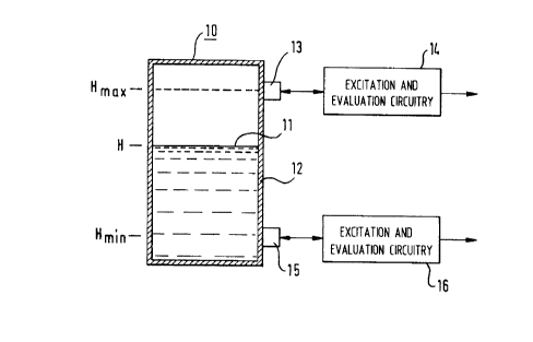
Fig. 1 shows a container 10 which is filled up to a level H
with a liquid 11. The level H at which the surface of the
liquid 11 is located above the bottom of the container 10, is
the momentary level in the container. The level is required not
to exceed a maximum level Hmax and not to drop below a minimum
level Hmin~ Each of these limit values of the level is also
termed "limit level".
218784 ~
6
Attached to the outer surface of the container wall 12 for
monitoring the upper limit level Hmax is a level sensor 13
which is connected to an excitation and evaluation circuitry
14. Attached to the outer surface of the container wall 12 for
monitoring the lower limit level Hmin is a level sensor 15
which is connected to an excitation and evaluation circuitry
16. Each of the two sensors 13 and 15 is configured so that
with the aid thereof it can be defined through the container
wall 12 whether the liquid 11 in the container 10 is at the
level of the sensor 13 and 15, respectively, or not. For this
purpose each of the two sensors 13 and 15 is conf figured as an
ultrasonic sensor which is able, when excited by an electrical
alternating voltage pulse furnished by the corresponding
excitation and evaluation circuitry 14 and 16, respectively, to
send an ultrasonic pulse to the container wall 12 and to
convert received ultrasonic signals into electrical alternating
voltage signals which are transferred to the circuitry 14 and
16, respectively. The circuitry 14 and 16, respectively,
evaluates the received signals and provides at the output a
signal which indicates whether the level in the container 10
lies above or below the limit level to be monitored. To
establish this it is thus not necessary to provide an opening
in the container wall 12 or to introduce the sensor into the
interior of the container 10. It is for this reason that the
sensors 13 and 15 are also not in direct contact with the
liquid 11.
The two sensors 13 and 15 as well as the associated electronic
circuitries 14 and 16, respectively, are configured absolutely
identical. Accordingly, in the following the description
relates merely to the sensor 13 and the circuitry 14, this
description applying just the same to the sensor 15 and the
circuitry 16.
Fig. 2 shows a perspective view of the sensor 13, and the Figs.
3 and 4 show section views of the sensor 13 secured to the
container wall 12. Fig. 3 shows a longitudinal section of the
sensor 13 for the case that the container wall is flat, and
218784.x.
Fig. 4 shows a transverse section through the sensor for the
case that the container wall is cylindrical. The excitation and
evaluation circuitry 14, which in Fig. 1 is illustrated
separately from the the sensor 13 for the sake of clarity, is
assembled together with the sensor 13 in the embodiment
illustrated in Figs. 2 to 4.
The sensor shown in Fig. 2 consists of a sensor block 20,
containing all components of the ultrasonic sensor and the
excitation and evaluation circuitry, and of an adapter 21 which
serves to secure the sensor block 20 to containers of differing
shape and size as well as of differing materials. The sensor
block 20 has a sensor housing 22 which is closed off by a cover
23 secured to the sensor housing 22 by means of screws 24. The
sensor block 20 is secured to the adapter 21 by means of screws
26 which pass through holes in the protuberances 27 on the
narrow sides of the sensor housing 22 and are screwed into
tappings in corresponding protuberances 28 on the adapter 21.
After having released the two screws 26 the complete sensor
block can be removed from the adapter 21 secured to the
container wall 12. Vice-versa for fitting a sensor, the adapter
21 is secured without the sensor block 20 to the desired
location of a container wall by suitable means and subsequently
the sensor block 20 with the ultrasonic sensor assembled ready
for operation is mounted on the adapter 21 and secured by means
of the screws 26. A terminal block 29 projecting from one side
of the sensor housing 22 permits connecting the circuitry
accommodated in the sensor housing 22 to outer connecting
leads.
The adapter 21 is a plastics moulding substantially comprising
a plate 30, the contour of which corresponds to the contour of
the sensor housing 22, i.e. in the example shown, rectangular.
Molded around the plate 30 is a frame 31 which is provided on
the side facing the container wall with a groove 32 into which
a seal 33 is inserted. On the longitudinal sides of the adapter
21, which in the case of a cylindrical container 10 rest on the
container wall 12 along the generatrices, the frame 31 has a
218144
8
consistent height. On the transverse sides which in the case of
a cylindrical container 10 rest on the container wall 12 along
the periphery, the frame 31 includes a recess 34 in the shape
of a circular arc as is evident in Fig. 2 on the front
transverse side thereof. The radius of curvature of the recess
34 corresponds to the radius of the container wall 12 of a
container 10 having the smallest diameter at which the adapter
21 is to be attached. When the ultrasonic sensor 13 is intended
for containers, the nominal width (diameter) of which amounts
to at least 200 mm, the radius of curvature of the recess 34 is
thus 100 mm.
The seal 33 is configured so that its sealing surface intended
for contact with the container wall lies in a plane when the
adapter 21 is not yet applied to the container wall 12 and thus
the seal 33 is still to change shape. So that this requirement
is satisfied the seal 33 has a consistent height along the
longitudinal sides of the frame 31, while its height in the
region of each transverse side increases in keeping with the
shape of the recess 34 in the shape of a circular arc towards
the center. As evident from the Figs. 3 and 4 the seal 33 is
preferably configured with two sealing lips 35, between which a
notched recess 36 exists. The sealing lips 35 are relatively
low along the longitudinal sides of the frame 31 (Fig. 4) and
the depth of the notched recess 36 is at this location
correspondingly small, whereas along the transverse sides of
the frame 31 the height of the sealing lips 35 and the depth of
the notched recess 36 increase to the same extent as the height
of the seal 33. Since the section plane of the sectioned view
of Fig. 3 passes through the locations at which the recesses 34
are deepest, the sealing lips 35 have in this section view a
maximum height and the notched recesses 36 a maximum depth.
When the adapter 21 is secured to a flat container wall 12
(Fig. 3) the sealing lips 35 are pressed together in the region
of the recesses 34 to the same extent as in the region of the
straight longitudinal sides of the frame 31, i.e, relatively
slightly, whereas when the adapter 21 is secured to a
-2187844
cylindrical container wall 12 (Fig. 4), the sealing lips change
shape more in the region of the recesses 34 than in the region
of the straight longitudinal sides of the frame 31, i.e. all
the more, the smaller the radius of curvature of the container
wall is. This more pronounced change in shape is made possible
by the greater height of the sealing lips 35 and the greater
depth of the notched recess 36 in this region. In all cases,
however, the sealing lips 35 are in sealing contact with the
container wall along the entire periphery of the adapter 21.
The section view of Fig. 3 shows a first possibility of
securing the adapter 21 to the container wall 12: welded to the
container wall 12 are stud bolts 37 which protrude through the
openings of bushes 38 formed integrally with the plate 30 of
the adapter 21. Screwed onto the ends of the stud bolts 37
protruding from the bushes 38 are nuts 39 which tension the
plate 30 while pressing the seal 33 together against the
container wall 12. If required, spacers protruding downwards to
the container wall 12 may be formed on the plate 30 which
determine a defined spacing of the plate 30 from the container
wall 12 and thus a defined position of the adapter 21 as
regards the container wall 12.
In the left-hand half of Fig. 4 another way of securing the
adapter 21 to the container wall 12 is illustrated. For this
purpose one leg of an angular bracket 41 formed of heavy gauge
sheet metal is inserted in a side slot 40 provided in the
middle of each longitudinal side of the adapter 21 and secured
therein by a screw 42. The other leg of the angular bracket 41,
which is upswept at a right angle, is bent hook-shaped at the
end. This hook-shaped bent end clasps a rail 43 which is welded
to the container wall 12 and it is clamped firmly in place to
the rail 43 by means of at least one~screw 44. This kind of
fastening permits defining the position at which the sensor 13
is to be applied to the container 10 by simple means and, where
necessary, to subsequently change the position by shifting the
adapter 21 along the rail 43.
23292-93
2187844
In conclusion, it is shown in the right-hand half of Fig. 4
that it is also possible to secure the adapter 21 by means of a
clamping strap 49 placed around the container. For this purpose
an angular bracket 41 is inserted in each of the slots 40 on
both sides of the adapter 21 and hook-shaped brackets are
hooked onto the bent upper end of the upswept legs of the two
angular brackets 41, these brackets being provided at the ends
of the clamping strap 49 placed around the container as is
illustrated in the right-hand half of Fig. 4 for one of the two
angular brackets. Such a clamping strap fastening provides an
even greater freedom of choice in selecting the location to
apply the sensor 13 to the container l0 and has additionally
the advantage that no intervention needs to be undertaken on
the container itself. Hooking the clamping strap 49 into place
at the two upper ends of the upswept legs of the angular
bracket 41 results in the points at which the force exerted by
the clamping strap 49 is applied lie relatively high on the
adapter 21. This is of advantage because particularly in the
case of containers having a large radius of curvature the
components of the force pressing against the container
significantly increase with the height of the point of
application.
The stud bolts 37 or the rails 43 may be secured to the
container wall 12 instead of by welding also by adhesive
bonding, this type of securement of the adapter 21 also being
suitable for containers of a plastics material.
The sensor housing 22 is divided into two spaces 46 and 47 by a
transverse wall 45. In the outer space 46 facing away from the
container wall 12 the excitation and evaluation circuitry 14 is
accommodated which in the usual way is made up of electronic
components which are mounted on a circuit board 48. In the
inner space 47 facing the container wall 12 and the adapter 21
the components of the ultrasonic sensor 13 are fitted, to which
in particular an electroacoustical transducer 50 belongs which
serves to convert an alternating voltage pulse furnished by the
excitation and evaluation circuitry into an ultrasonic pulse
2187844
which is transferred to the container wall 12, and to convert
ultrasonic vibrations which it receives from the container wall
12 into an electrical alternating voltage which is transferred
to the excitation and evaluation circuitry.
The electroacoustical transducer 50 is illustrated in more
detail in Fig. 5. It contains as the active component a piezo-
electric element 51 which in the known way is a slice of a
piezoelectric crystal on both sides of which metallizations are
applied which serves as electrodes. When an alternating voltage
is applied to the electrodes, the piezoelectric crystal is
excited to produce physical vibrations at the frequency of the
alternating voltage, and when physical vibrations are transferred to
the piezoelectric crystal it produces between the electrodes an
alternating voltage having the frequency of the physical
vibrations. In Fig. 5 the electrodes are not illustrated since
due to the minute thickness of the metallization as compared to
the thickness of the piezoelectric crystal they are not
visible.
The piezoelectric element 51 is arranged in the interior of a
pot-shaped transducer housing 52 and is in contact with the
bottom 53 of the transducer housing 52 which simultaneously
forms the diaphragm of the ultrasonic transducer 50. The
transducer housing 52 is made. of a plastics material.
On the side of the piezoelectric element 51 facing away from
the diaphragm 53 a circuit board 54 is arranged which carries
the components of a circuit serving to couple the piezoelectric
element 51 to the excitation and evaluation circuitry 14. The
circuit board 54 is located spaced away from the piezoelectric
element 51, and the space between the circuit board 54 and the
piezoelectric element 51 is filled with a potting compound 55
which is filled in fluid condition and then solidifies. The
side of the piezoelectric element 51 facing away from the
diaphragm 53 is covered by a disk 56 of a closed-pore foamed
material which prevents the potting compound 55 from coming
into direct contact with the piezoelectric element 51. Also the
B
12 ~ ~ 18 7$,~ 4
space above the circuit board 54 is filled up to such a level
with the potting compound 55 that all circuit components
mounted on the circuit board 54 are embedded in the potting
compound 55. The potting compound 55 is prescribed for reasons
of explosion-protection, it in addition effecting dampening of
ultrasonic waves emitted to the side opposite the diaphragm 53.
To facilitate installing the piezoelectric element 51 and the
circuit board 54, as well as encapsulating these parts, a
mounting sleeve 60 is provided which is illustrated in more
detail in the Figs. 6, 7 and 8. The mounting sleeve 60 is a
molding of a plastics material which is shown in Fig. 6 in the
plan view, in Fig. 7 in longitudinal section along the broken
line A-A of Fig. 6 and in Fig. 8 in a perspective view. The
mounting sleeve 60 has a widened cylindrical section 61, a
narrowed cylindrical section 62 of smaller diameter and a
conical section 63 between the two cylindrical sections 61 and
62. The outer diameter of the widened cylindrical section 61
corresponds to the inner diameter of the pot-shaped transducer
housing 52, and the inner diameter of the narrower cylindrical
section 62 corresponds to the diameter of the piezoelectric
element 51. The narrower cylindrical section 62 and the conical
transition section 63 are divided into six segments 64 by
cutouts. At each segment 64, a paw 65 protruding radially
inward is formed at the transition between the cylindrical
section 61 and the conical section 63. Below each paw 65 an
abutment nose 66 is formed which extends downwards only over a
part of the height of the cylindrical section 62 and protrudes
only slightly downwards radially. At the transition between the
conical section 63 and the widened cylindrical section 61 a
shoulder 67 is formed. In the wall of the widened cylindrical
section 61 at each of two positions diametrally opposed to each
other by cutouts a flexible latch 68 is formed, the free end of
which protrudes slightly inwards and is located a distance away
from the shoulder 67 which corresponds to the thickness of the
circuit board 54. A rib 69 formed on the periphery of the
widened cylindrical section 61 engages a corresponding groove
in the transducer housing 52, as a result of which the mounting
2187844
13
sleeve 60 is prevented from turning in the transducer housing
52.
The described configuration of the mounting sleeve 60 permits
simple, speedy and precise assembly of the components of the
ultrasonic transducer 50 outside of the transducer housing 52.
The piezoelectric element 51 with the disk 56 of a closed-pore
foamed material placed thereon is introduced into the narrowed
cylindrical section 62 from underneath until the piezoelectric
element 51 comes up against the ends of the abutment noses 66,
thus precisely defining the radial and axial position of the
piezoelectric element 51 in the mounting sleeve 60. The
diameter of the foamed material disk 56 is somewhat smaller
than the diameter of the piezoelectric element 51 and
corresponds to the spacing between two abutment noses 66
located diametrally opposed to each other, and the thickness of
the foamed material disk 56 corresponds to the height of the
abutment noses 66. Accordingly, the paws 65 locate on the upper
side of the foamed material disk 56 when the piezoelectric
element 51 is introduced to abutment in the mounting sleeve 60,
and the abutment noses 66 locate on the periphery of the foamed
material disk 56. As a result of this the radial and axial
position of the foamed material disk 56 is precisely defined in
the mounting sleeve 60, and the foamed material disk 56 is
maintained by the paws 65 in close contact with the upper side
of the piezoelectric element 51.
The circuit board 54 is circular and has a diameter correspon-
ding to the inner diameter of the widened cylindrical section
61 of the mounting sleeve 60. It is introduced from above into
the widened cylindrical section 61 until it rests on the
shoulder 67. During insertion the latches 68 are forced
outwards by the peripheral edge of the circuit board 54 until
the peripheral edge of the circuit board 54 has passed the ends
of the latches 68. Then, due to their elasticity, the latches
68 snap back inwards so that they clasp the upper side of the
circuit board 54 and hold the latter firmly on the shoulder 67,
as a result of which the position of the circuit board 54 is
2~~7844
14
fixed in the axial and radial direction in the mounting sleeve
60. The mounting sleeve 60 is then ready for being installed in
the transducer housing 52. For this purpose a drop of a hot-
curable adhesive is first applied to the bottom 53 of the
transducer housing 52, and subsequently the mounting sleeve 60
is inserted into the transducer housing 52 until the
piezoelectric element 51 comes into contact with the bottom 53,
the adhesive thereby being distributed in a thin layer between
the surfaces of the piezoelectric element 51 and the bottom 53
facing each other. The adhesive is then hardened by being
heated, the mounting sleeve 60 being weighted down by a weight
so that a defined layer of adhesive is attained. The layer of
adhesive ensures the contact between the piezoelectric element
51 and diaphragm of the ultrasonic transducer 50 formed by the
bottom 53 and it prevents the formation of a layer of air
between these parts.
The potting compound 55 is then filled into the mounting sleeve
60 from above. This potting compound flows through openings
provided therefor in the circuit board 54 also into the space
between the circuit board 54 and the foamed material disk 56.
The foamed material disk 56 prevents the potting compound 55
from coming into contact with the upper side of the piezo-
electric element 51. The paws 65 which force the edge of the
foamed material disk 56 onto the upper side of the piezo-
electric element 51 prevent the potting compound 55 from
creeping between the foamed material disk 56 and the piezo-
electric element 51.
Serving installation of the pot-shaped transducer housing 52 in
the sensor housing 22 is a mounting part 70 having a flange 71
on which a guide bush 72 is formed. The transducer housing 52
is pushed into the guide bush 72 , the inner diameter of which
corresponds to the outer diameter of the transducer housing 52
so that the transducer housing 52 is a sliding fit in the guide
bush 72. The collar 57 on the transducer housing 52 prevents
the transducer housing 52 from emerging from the guide bush 72.
In the open end of the transducer housing 52 a spring cup 73 is
2187844
inserted which in turn features a collar 74 supported by the
end of the transducer housing 52. The spring cup 73 receives
the one end of a coil compression spring 75. Running around the
edge of the flange 71 is a collar 76, the inner diameter of
which corresponds to the outer diameter of a carrier tube 77
formed on the transverse wall 45.
Prior to attaching the mounting part 70 to the carrier tube 77
a connecting lead 78, which is soldered to the circuit board 54
and is intended to connect the ultrasonic transducer 50 to the
excitation and evaluation circuitry 14, is inserted through a
tube socket 79 standing off from the transverse,wall 45 to the
opposing side. On the flange 71 a sealing ring 80 is placed to
which the outer edge of an annular cuff 81 is secured, the
inner edge of which is connected to an elastic ring 82 placed
around the transducer housing 52. Then, the collar 76 is placed
over the carrier tube 77 and the flange 71 is secured by means
of screws 83 which are screwed into the thickened wall sections
of the carrier tube 77 and of which one is to be seen in Fig.
4. The coil compression spring 75 is dimensioned so that it is
compressed between the spring cup 73 and the transverse wall 45
to achieve a desired pretension when the mounting part 70 is
secured to the carrier tube 77.
Following this, the connecting lead 78 can be soldered to the
terminals provided on the circuit board 48, and the outer space
46 Can be filled with a potting compound practically up to the
level of the tube socket 79. The tube socket 79 prevents
potting compound from flowing into the inner space47 .
The sensor block 20 is now fitted ready for operation and it
can be secured to the adapter 21. For this purpose the guide
bush 72 is inserted through an opening in the plate 30 of the
adapter 21 so that the bottom of the transducer housing 52,
i.e. the diaphragm 53 of the ultrasonic transducer 50, is in
contact with the outer surface of the container wall 12. When
the sensor block 20 is moved in the direction of the adapter
21, the transducer housing 52 is firmly held by the container
23292-93
21884 ~
wall 12 so that it is shifted into the guide bush 72, as a
result of which the spring 75 is further compressed. Once, in
conclusion, the sensor block 20has been secured to the adapter
21 by means of the screw 26, the diaphragm 53 is urged against
the container wall 12 by the force defined by the spring 75.
It will be appreciated from comparing the Figs. 3 and 4 that in
applying the sensor 13 to a flat container wall 12 (Fig. 3) the
ultrasonic transducer 50 protrudes further from the guide bush
72 than in the case of a curved container wall 12 (Fig. 4), the
contact of the diaphragm 53 with the container wall 12 being
assured in each case by the force defined by the spring 75.
For satisfactory functioning of the ultrasonic sensor and
achieving a good efficiency it is a substantial requirement
that a good acoustical coupling exists, on the one hand,
between the piezoelectric element 51 and the diaphragm 53 and,
on the other hand, between the diaphragm 53 and the container
wall 12, it being particularly a substantial requirement that
no layers of air exist between these parts since these would
result in high jumps in the acoustical impedance on the way
from the piezoelectric element 51 to the container wall 12 and
back. The preferred embodiment of the diaphragm 53 with which
this good acoustical coupling can be achieved will now be
explained on the basis of Figs. 9 and 10.
It is evident from the section view of the transducer housing
52 in Fig. 9 that on the inside of the diaphragm 53 a
depression 85 is formed around the periphery which surrounds
the active diaphragm region 86 on which the piezoelectric
element 51 rests. As already explained, for preventing any air
layer whatsoever between the piezoelectric element 51 and the
active diaphragm region 86 prior to the mounting sleeve 60
being inserted into the transducer housing 52, an adhesive is
applied to the exposed surface of the piezoelectric element 51
which, when the piezoelectric element 51 is pressed on the
active diaphragm region 86 on insertion of the mounting sleeve
60, is distributed between the surfaces facing each other of
v
..~.. 17 .~ 218 ~ 8 ~ 4
these two parts. The depression 85 serves to receive excess
adhesive displaced from the space between the piezoelectric
element 51 and the active diaphragm region 86. Preferably a
hot-curable adhesive is used, since this does not lose its
properties even at high operating temperatures.
On the outside of the diaphragm 53 a series of protuberances 87
is formed, arranged in a circular ring coinciding roughly with
the periphery of the active diaphragm region 86 (Fig. 10) . In
the example illustrated the protuberances 87 have the form of
round pimples. The annular region 88 of the diaphragm 53
located outside of the ring of protuberances 87 is slightly
recessed with respect to the diaphragm surface 89 located
within the ring. On the inside of the diaphragm 53 a depression
90 is evident in Fig. 9 which serves to receive the solder
junction through which a connecting lead is connected to the
electrode of the piezoelectric element 51 located on the
diaphragm. A correspondingly flared protuberance 91 is located
on the outer surface of the diaphragm 53 opposite to this
depression.
In fitting the sensor 13 to the container wall 12, i.e. in the
example as previously described in fitting the sensor block 20
to the adapter 21, a coupling layer is inserted between the
diaphragm 53 and the container wall 12, this coupling layer
being of a material which prevents the formation of an air
layer between the diaphragm 53 and the container wall 12 and
provides a good acoustical coupling between the diaphragm and
the container wall. The protuberances 87 which come into direct
contact with the container wall 12 determine the thickness of
the coupling layer.
A material suitable for the coupling layer is, for instance,
the silicone gel commercially available under the tradename
*.
blacker SilGe1 612. This is a 2-component silicone rubber which
after mixing of the two components solidifies into a very soft,
gel-like vulcanized material by additive cross-linking. This
material is after mixing of the two components initially very
* trade-mark
218844
thin which is unfavorable since it poses the risk of flowing
away prematurely when applied to the diaphragm surface 89,
prior to the diaphragm 53 being placed on the container wall
12. This is why the silicone gel is reinforced preferably by
the admixture of glass fibers, for example in a proportion of
50~ by volume. These glass fibers may have a diameter of 30 um
and a length of 400 lam . Due to the glass fibers the viscosity
of the silicone gel is increased so that premature flow off is
prevented. In addition to this the glass fibers also enhance
the acoustical impedance of the coupling layer which is
favorable since it then approaches the acoustic impedance of
the plastics diaphragm 53.
When mounting the diaphragm 53 on a flat container wall 12
excess material of the coupling layer is able to be displaced
through the spaces between the protuberances 87. For this
reason it is not advisable to provide a closed ring as a spacer
for determining the thickness of the coupling layer.
When the diaphragm 53 is mounted on a cylindrical container
wall 12, contact materializes between the protuberances 87 and
the container wall 12 substantially only along a generatrix of
the container. The only aspect important for proper functioning
of the ultrasonic sensor is the situation existing along this
line of contact; in this case, too, the protuberances 87
determine the thickness of the coupling layer along this line
of contact.
It is a substantial requirement for the good coupling achieved
by the coupling layer between the diaphragm 53 and the
container wall 12 that the diaphragm is made of a plastics
material, because the acoustical impedance of the plastics
diaphragm and that of the coupling layer are of the same order
of magnitude so that no large jumps in impedance materialize.
This permits using a relatively thick coupling layer. The
thicker the coupling layer the better is the thermal and
physical stability of the sensor. Upwardly the thickness of the
coupling layer is limited by the fact that its thickness
B
2187~~~~.
19
resonance is required to be above the ultrasonic frequency
applied. When using the aforementioned glass-fiber reinforced
silicone gel the thickness of the coupling layer and thus the
height of the protuberances may amount to about 0.2 mm.
Since the diaphragm 53 is part of the transducer housing 52,
the complete transducer housing 52 must be made of a plastics
material which is suitable for the diaphragm 53. One
substantial requirement on the material of the diaphragm is
that the dynamic glass transition point, i.e. the temperature
at which the plastics material makes the transition from the
crystalline phase into the amorphous phase, is to be above the
highest operating temperature occuring. Particularly good
results have been obtained with polyether etherketone (PEEK).
Fig. 11 shows a simplified block diagram of the excitation and
evaluation circuitry 14. The ultrasonic transducer 50 is
depicted symbollically by a circuit block.
A control circuit 100 controls all functions of the various
circuit components. Belonging thereto is a frequency synthe-
sizer circuit 102 which generates an electrical alternating
voltage having the frequency which the ultrasonic signal
generated by the ultrasonic transducer 50 is required to have.
This frequency is determined by a control signal which is
applied by the control circuit 100 to a control input of the
frequency synthesizer circuit 102.
The output of the frequency synthesizer circuit 102 is
connected to the signal input of a transmission pulse gate 104
which at its control input receives from the control circuit
100 an opening pulse every time the ultrasonic transducer 50 is
required to generate an ultrasonic pulse. The transmission
pulse gate 104 is opened by the opening pulse so that the
alternating voltage generated by the frequency synthesizer
circuit 102 is applied to the ultrasonic transducer 50 for the
duration of the opening pulse.
20 2187~4~'~
At the receiving end the terminal of the ultrasonic transducer
50 is connected to the input of an envelope generator 110 which
contains in a series arrangement a high-pass filter 112, an
amplifier 114, a rectifier 116 and a low-pass filter 118. The
high-pass filter 112 passes only frequencies above the lower
working frequency of the ultrasonic transducer 50. The
amplifier 114 amplifies the output signal of the high-pass
filter 112 for no-problem rectification. By means of the
rectifier 116 and the output low-pass filter 118 the envelope
signal of the alternating voltage signal furnished by the
ultrasonic transducer 50 is formed.
One substantial feature of the excitation and evaluation
circuitry of Fig. 11 consists of the transmission frequency
generated by the frequency synthesizer circuit for excitation
of the ultrasonic transducer 50 being precisely equal to the
thickness resonant frequency of the container wall 12 at which
the ultrasonic sensor 13 is fitted. This thickness resonant
frequency may be the fundamental frequency of the thickness
resonance or, in the case of thick container walls, in which
this fundamental frequency would be ,too low, the second order
of resonance. The plots of Fig. 12 show the envelope signal
received at the output of the envelope generator 110 under this
assumption. The plot A of Fig. 12 shows the envelope signal H
as a function of time t for the case that the level in the
container 10 lies above the level to be monitored by the
ultrasonic sensor, so that the measurement point, i.e. the
point on the container wall 12 at which the ultrasonic sensor
is fitted, is covered by the liquid 11. This corresponds to the
status of the sensor 15 in Fig. 1. Plot B of Fig. 12 shows the
envelope signal H as a function of the time t for the case that
the level in the container 10 lies below the level to be
monitored by the ultrasonic sensor, so that the measurement
point is not covered by the liquid 11. This corresponds to the
status of the sensor 15 in Fig. 1.
In plot A the transmission pulse S is illustrated which begins
at time t0 and ends at time tl. Due to the transmission pulse,
218784
21
excitation of the container wall 12 occurs at the point at
which the ultrasonic transducer 50 transfers ultrasonic
vibrations to produce thickness vibrations at the natural
resonant frequency which gradually build up as illustrated by
the dashed line. The transmission pulse is required to be so
long that the thickness vibrations achieve the stationary
condition prior to the end of the transmission pulse. The
thickness vibrations do not cease instantly at the end of the
transmission pulse at time tl, they instead dying off gradually
due to the after-vibration of the container wall. The envelope
signal H thus contains subsequent to the end of the trans-
mission pulse S the envelope N of the after-vibration of the
container wall 12. Since, however, the container wall 12 at the
point of vibration is dampened by the liquid by which it is
covered, the dying off occurs relatively quickly so that at the
time t2, which is located relatively shortly behind the time
tl, it is substantially terminated and after this time t2
practically no further envelope signal caused by the after-
vibration exists.
The container wall vibrating at the thickness resonance also
radiates ultrasonic waves into the interior of the container.
Since the vibrating measurement point is covered by the liquid,
the ultrasonic waves are propagated in the liquid so that they
attain the opposite container wall where they are reflected.
The reflected ultrasonic waves arrive as an echo signal at the
point at which the ultrasonic sensor is fitted, and they are
transferred via the container wall to the ultrasonic transducer
50 which converts them into an electrical signal which is
applied to the input of the envelope generator 110. This is why
the envelope E of the echo signal reflected at the opposite
container wall appears in the envelope signal output by the
envelope generator 110 at time t5. Experience has shown that
this echo signal is obtained as an optimum when the
transmission frequency corresponds to the thickness resonant
frequency of the container wall.
218784.
22
The plot B of Fig. 12 also shows the transmission pulse S which
begins at time t0 and ends at time tl, as well as the envelope
N of the after-vibration of the container wall 12. Since the
vibrating measurement point of the container wall 12 is not
covered by the liquid it is dampened less strongly than in the
case of plot A, so that the thickness resonant vibrations of
the container wall die out slower. The envelope N of the after-
vibration thus has still a considerable height at time t2 at
which it has practically disappeared when the measurement point
is covered.
In contrast, no echo signal E exists in the envelope signal H
of the plot B at the time t5, this being due primarily to the
fact that the emission of ultrasonic waves in air is very
slight due to the large difference in the acoustical impedances
of the container wall and of air. Should nevertheless a weak
echo be detected, it would occur substantially later than at
time t5 due to the great difference of the speed of sound in
liquids and in air.
The phenomena explained on the basis of the plots A and B are
evaluated in the excitation and evaluation circuitry of Fig. il
to determine whether the measurement point of the container
wall 12 is covered by liquid or not.
For this purpose the envelope signal H furnished by the
envelope generator 110 is applied in parallel to an integrator
120 and a peak detector 122. The integrator 120 is controlled
by a control signal furnished by the control circuit 100 so
that it, following each emittance of a transmission pulse S,
integrates the envelope signal H in a time window F1 between
the times t2 and t3. The peak detector 122 is controlled by a
control signal furnished by the control circuit 100 so that it
establishes the peak value of the envelope signal H in a time
window F2 between the times t4 and t6 which contains the time
t5 of the echo signal E.
298~8e~4
23
Integration of the envelope signal H in the time window F1
enhances the reliability in determining whether an after-
vibration exists after the time t2 or not, as compared to a
simple sensing of the envelope signal at a time which lies
behind the time t2. It will be appreciated from comparing the
plots A and B of Fig. 12 that the integral of the envelope
signal H in the time window F1 in the case of plot B is quite
considerably larger than in the case of plot A, even if in the
last case sporadic disturbances were to occur in the time
window F1. The integrator 120 provides at the output an analog
signal I which indicates the value of the integral.
The time window F2 is necessary because the time t5 of the echo
signal E may vary due to differing speeds of sound in the
liquid. Changes in the speed of sound may result in the same
liquid due to changes in temperature. In addition, differing
speeds of sound may exist when other liquids are filled into
the container. The time window F2 is selected so that under all
existing conditions the echo signal lies in this time window.
The peak detector 122 provides at the output an analog signal P
which indicates the peak of the envelope signal H established
in the time window F2.
The output of the integrator 120 is connected to the input of
an analog-to-digital converter 128 via a switch 124. The output
of the peak detector 122 is also connected to the input of the
analog-to-digital converter 128 via a switch 126. The two
switches 12~ and 126 can be opened and closed by control
signals furnished by the control circuit 100. The output of the
analog-to-digital converter 128 is connected to a
microprocessor 130.
In the microprocessor 130 the digitized output signals of the
integrator 120 and the peak detector 122 are evaluated
according to the following criteria:
- signal I is greater than an assigned threshold value:
measurement point not covered;
v
24 2187844
- signal I is smaller than the assigned threshold value:
measurement point is covered;
- signal P is greater than an assigned threshold value:
measurement point is covered;
- signal P is smaller than the assigned threshold value:
measurement point not covered.
Accordingly, for each of the two states "uncovered" and
"covered" a positive signal value ("signal present") and a
negative signal value ("signal missing") exist:
- in the "uncovered" status signal I is present, while signal P
is missing;
- in the "covered" status signal P is present, while signal I
is missing.
Monitoring the level is thus achieved with high error detection
reliability. As long as only one of the two signals I and P
exceeds the assigned threshold value in each case, it is
assured that the monitored level is correctly determined. When
none of the two signals I and P exceeds the assigned threshold
value, or if both signals I and P exceed the assigned threshold
value at the same time, it is evident that an error exists.
The microprocessor 130 furnishes the result of the signal
evaluation to the control circuit 100 which accordingly outputs
a signal at an output 100a which indicates whether the level in
the container lies above or below the level to be monitored, or
whether an error status exists.
As indicated above, the transmission frequency generated by the
frequency synthesizer circuit 102 needs to correspond as
accurately as possible to the thickness resonant frequency of
the container wall 12. This thickness resonant frequency
2187844
depends on the material and the thickness of the container
wall. For containers of metal or glass having a wall thickness
between 2 mm and 15 mm the evaluated thickness resonant
frequency is in the range of about 0.6 MHz to 2 MHz, for
plastics containers having the same wall thickness the range is
0.3 MHz to 0.6 MHz. Furthermore, the thickness resonant
frequency for a covered measurement point is somewhat different
to the thickness resonant frequency for an uncovered
measurement point. In conclusion, the thickness resonant
frequency changes in operation particularly as a function of
the temperature.
For these reasons the thickness resonant frequency of the
container wall is established with the measurement point
covered and uncovered and memorized in the control circuit 100
prior to putting the measurement device into operation. These
resonant frequencies correspond to the maximum peak value
signal P in the covered condition or the maximum integral
signal I in the uncovered condition. In addition, the thickness
resonant frequencies are corrected in operation at certain time
intervals in a specific range about the frequencies found in
setting up the measurement device.
The criterion for correcting the frequency used for the
integral measurement is a maximum integral signal I, the
criterion for correcting the frequency used for the peak value
measurement is a maximum peak value signal P. When the
frequency values established in this way deviate by more than a
certain tolerance threshold from the memorized frequency values
the memorized frequency values are correspondingly corrected.
For taking into account the differing thickness resonant
frequencies for a covered and an uncovered measurement point
the measurement is made preferably in consecutive transmission
periods alternatingly with the one or the other memorized
thickness resonant frequency.
2181844
26
In a transmission period the control circuit 100 prompts
excitation of the ultrasonic transducer 50 at the transmission
frequency corresponding to the resonant frequency with the
maximum integral signal I. At the same time the control circuit
100 opens the switch 126 so that an output signal P of the peak
detector 122 in this transmission period is not evaluated. If
the measurement point is in reality not covered, the peak
detector 122 would in any case furnish no useful output signal
in this transmission period, whereas if the measurement point
is covered the output signal of the peak detector 122 would not
be an optimum. If, on the other hand, the transmission
frequency has the value at which the integrator 120 furnishes
the optimum output signal, then the measurement point is in
reality not covered.
In the next transmission period the control circuit 100 prompts
excitation of the ultrasonic transducer 50 at the transmission
frequency corresponding to the resonant frequency with the
maximum peak value signal P, and it opens the switch 124 while
switch 126 is closed. Accordingly, in this transmission period
the output signal I of the integrator 120 is not evaluated. If
the measurement point is in reality covered, the integrator 120
would in any case furnish no useful output signal in this
transmission period, whereas if the measurement point is not
covered the output signal of the integrator 120 would not be an
optimum, because it was not made at the correct thickness
resonant frequency. If, on the other hand, the transmission
frequency has the value at which the peak detector 122
furnishes the optimum output signal, then the measurement point
is in reality covered.
These two transmission periods are repeated alternately, this
achieving that the microprocessor 130 receives output signals
from the integrator 120 in the uncovered condition and from the
peak detector 122 in the covered condition which are usable in
each case (i.e. exceeding the assigned threshold value) as
obtained at the correct thickness resonant frequency.
2187844
In this operating mode with alternating transmission frequen-
cies too, the error detection reliability as explained above
remains assured, i.e. an error being present when in the two
consecutive transmission periods the two signals I and P do not
exceed their assigned threshold values or the two signals I and
P exceed their assigned threshold values.
If, due to an indicated error status, it is established that
either obtaining the after-vibration signal by the integrator
120 or obtaining the echo signal by the peak detector 122 is
missing or defective, monitoring the level can be continued
with the aid of the other signal in each case, by the switch
124 and 126 assigned respectively to the faulty signal
remaining continually open. Although the enhanced error
detection reliability as described above is then missing, the
measurement device still operates with the same error detection
reliability as for known measurement assemblies. The same
procedure may be used if sensing one of the two signals for a
specific material is not possible. Thus, the measurement device
is highly versatile in use without necessitating changes in
design.
Since in the device as described above the ultrasonic trans-
ducer 50 is excited at a thickness resonant frequency of the
container wall 12, the piezoelectric element 51 must be
configured so that it operates satisfactorily at the thickness
resonant frequency used in each case. Disk-shaped piezoelectric
elements exhibit two vibration modes, namely thickness
vibrations and radial vibrations having differing resonant
frequencies. The radial vibrations are not suitable for the
described application, however, because they cannot be
practically transferred via the plastics diaphragm 53 and the
soft coupling layer so that the energy of radial vibrations is
to be viewed as a loss. In the case of conventional solid
ceramic piezoelectric elements, for example of lead-zirconate
titanate (PZT) the radial vibrations are very pronounced and
can only be separated from the thickness vibrations with
difficulty. Accordingly, the radial vibrations prove to be a
v
2 ~$ ~8~ 4
28
disturbance particularly in the after-vibration range. In
particular, however, the useful frequency ranges of con-
ventional piezoelectric elements occupy a very narrow band,
whereas in the device as described above the piezoelectric
elements, depending on the wall thickness and the material of
the container, need to be operated at frequencies in the range
of 0.3 MHz to 2 MHz. When employing conventional piezoelectric
elements this would mean that practically for each container a
precisely adapted piezoelectric element would need to be
provided. This would obviously be highly unfavorable both for
reasons of production and stocking and as regards an efficient
mounting of the level monitoring device.
To get round these difficulties, use is thus made of a piezo-
electric element 51 which consists of a porous piezoelectric
ceramic having a type 3-3 connectivity.
The term "connectivity" was introduced by R.E. Newnham to
characterize the structures of multi-phase solids and also
applied to composite electroceramics (R.E,Newnham "Composite
Electroceramics, Ferroelectrics 1986, Vol. 68, pages 1-32). The
connectivity designates the spatial directions in a three-
dimensional right-angled system of coordinates in which the
components of each phase are fully connected to each other, 0
meaning that the components of each phase are fully connected
to each other in no spatial direction, 1 that the components of
each phase are fully connected to each other in only one
spatial direction, and so on. Thus "3-3 connectivity" means
that in the case of a two-phase solid the components of each of
the two phases are fully connected to each other in all three
spatial directions.
In the paper "Dielectric, elastic and piezoelectric properties
of porous PZT ceramics" by W. Wersing, K. Lubitz and J. Mohaupt
in Ferroelectrics 1986, Vol. 68, pages 77-97 the term
connectivity is also applied to porous ceramics which are
viewed as being two-phase solids in which the one phase is
formed by the ceramic material and the other phase by the
B
29 ~ 2 ~~ ~ 8
pores. Thus, in the case of a porous ceramic having a type
3-3 connectivity both the ceramic and the pores are fully
connected to each other in all three spatial directions.
Using a porous piezoelectric element 51 having the type 3-3
connectivity eliminates more or less all of the aforementioned
problems. For one thing the radial vibration modes are more
strongly dampened than with conventional piezoelectric
elements, the piezoelectric element behaving almost like a pure
thickness resonator. For another, the acoustical impedance is
closer to that of the plastics diaphragm 53 and the coupling
layer inserted between the diaphragm 53 and the container wall
12 as a result of which a better matching is achieved. Most of
all, however, the piezoelectric element is considerably wider
in band than a conventional piezoelectric element, thus making
it possible to cover the complete frequency range from 0.3 MHz
to 2 MHz with three to four piezoelectric elements.
However, the porosity of the piezoelectric element 51
necessitates a few special precautions, especially as regards
the potting compound 55 with which the space on the side of the
piezoelectric element 51 facing away from the diaphragm 53 is
filled. In the case of conventional piezoelectric elements the
encapsulation serves, on the one hand, to prevent cavities
forming and to encapsulate the electrical and electronic
components for reasons of explosion protection, and, on the
other, to provide acoustics attenuation on the side of the
piezoelectric element facing away from the diaphragm 53. For
the porous ceramic piezoelectric elements employed according to
the invention encapsulation for acoustical reasons would not be
necessary; however, the requirement remains to provide
encapsulation for reasons of explosion protection. This
requirement necessitates a potting compound which will easily
flow on being ffilled so that even small cavities and gaps are
filled out; preferably a fluid silicone potting compound of the
type~Sylgard 170 is used. There is, however, the contrary
requirement that the potting compound must not penetrate into
the pores of the piezoelectric element and alter the properties
* trade-mark
D
2187844
of the latter to disadvantage. Moreover, an acoustical
insulation of the potting compound from the piezoelectric
element is necessary to prohibit undesirable resonances and a
prolonged after-vibration. This requirement necessitates a
spatial separation of potting compound and piezoelectric
element, here again care must be taken, however, that no
cavities materialize in which an explosive gas may accumulate.
These requirements which contradict each other in part are
satisfied in the example embodiment as described above by the
following measures:
- inserting the disk 56 of closed-pore foamed material between
the piezoelectric element 51 and the potting compound 55;
- preassembling the piezoelectric element 51 and the foamed
material disk 56 in the mounting sleeve 60 outside of the
transducer housing 52.
The disk 56 for separating the piezoelectric element 51 from
the potting compound 55 preferably consists of a closed-pore
foamed silicone material, this being temperature-resistant and
preventing a penetration of the potting compound during the
hardening phase. Due to preassembly in the mounting sleeve 60
it is assured that the foamed material disk 56 is maintained,
even after insertion of the mounting sleeve 60 in the trans-
ducer housing 52, in sealing contact with the piezoelectric
element 51 by the paws 65 so that creepage of the potting
compound between the foamed material disk and the piezoelectric
element is prevented.
Due to the high impedance jumps, on the one hand, between the
piezoelectric element 51 and the foamed material disk 56 and,
on the other, between the foamed material disk 56 and the
potting compound 55, the closed-pore foamed silicone material
transfers no ultrasound, as a result of which the required
acoustical insulation is achieved. Moreover, the pliant foamed
silicone material adapts to the solder joint at the adjoining
B
218744
31
electrode of the piezoelectric element 51 and it surrounds the
connecting leads.