Note: Descriptions are shown in the official language in which they were submitted.
2187855
- 1 -
METHOD AND DEVICE FOR SECURING COMPUTERS
This invention relates to securing computers and is particularly
concerned with both physical security of computers and security of data
5 stored therein.
BACKGROUND OF THE INVENTION
Methods and devices for securing computers are well known.
Typically, the prior art addresses either physical security of the computer
10 through lock or alarm systems or security of data stored on the computer
through password protection.
There have been a few proposals that address both physical and data
security in a single apparatus. For example, Reinke et al, in U.S. Patent
4,908,608 teach a security device with an alarm device. The software
15 program, which activates the alarm device, is used like a key to enable and
disable the alarm. Optionally, a password can be established, allowing a
user owning the password, to enable and disable the alarm device. The
alarm password entry may prevent unauthorized access to the computer.
However, the operation of the alarm device depends upon the computer
20 being booted. Thus, anyone having knowledge of the presence of such a
device, could interrupt boot up the computer from the hard drive and
continue from a disk-drive to edit the AUTOEXEC.BAT and CONFIG.SYS
files to defeat the password feature.
In fact any security system relying on the AUTOEXEC.BAT file during
25 boot-up of an IBM compatible computer can be circumvented.
This problem has been recognized in a prior art device.
McClung et al, in U.S. Patent No. 4,951,249 teach a computer
security system for protecting the computer software from unauthorized
30 use. During boot-up of the computer the scheme replaces the keyboard
address and diskette address with addresses stored in ROM thereby locking
out these devices. When unauthorized use of the keyboard or diskette
insertion are attempted the boot-up routine ignores such and continues into
2187855
.
- 2 -
the security program. Because the keyboard is locked out, this device
requires an additional input device for an authorized user to login. A card
reader is used, together with a personal identification number (PIN) to
achieve this. Once the correct user has been thereby identified a password
5 procedure is used to allow access to the computer. While this system may
be effective at preventing overriding during boot-up, it requires an addition
input device and user cards. Hence, it is more costly and may require more
complex administrative support.
10 SUMMARY OF INVENTION
An object of the present invention is to provide an improved method
and device for securing computers.
In accordance with an aspect of the present invention there is
provided a device for securing a computer comprising means for interfacing
15 with the computer via a bus internal to the computer, means for monitoring
status of the computer and for establishing an alarm condition responsive
to a change in status, means for powering the device during intervals where
the computer is in an off state, means for interrupting normal start-up of the
computer during a basic input/output system portion thereof, and means for
20 accepting a password from a user to continue normal start-up of the
computer.
In accordance with another aspect of the present invention there is
provided a method of securing a computer comprising the steps of providing
storage for a stored password, during start-up of the computer, upon
25 addressing by the computer, initiating a program requesting input of the
password, comparing the password input to the stored password, and
allowing completion of start-up of the computer to continue if the password
input matches the password stored.
In accordance with a further aspect of the present invention there is
30 provided a device for securing a computer comprising a microcontroller, a
plurality of security sensors connected to the microcontroller, an alarm
output connected to the microcontroller, an interface connected to the
2187855
,
- 3 -
microcontroller for communicating with an internal bus in the computer, a
basic input and output system (BIOS) program store connected to the
microcontroller and the interface, a memory decoder connected to the
interface, the microcontroller and the BIOS program store, a non-volatile
store for security parameters and passwords, and a power circuit for
powering the device during intervals when the computer is off.
Advantages of the present invention include combining physical
security of the computer with data security and providing password
protection that cannot be bypassed by an informed user.
BRIEF DESCRIPTION OF THE DRAWINGS
The present invention will be further understood from the following
description with reference to the drawings in which:
FIG. 1 illustrates, in a block diagram, a computer security device in
accordance with an embodiment of the present invention;
FIG. 2a illustrates, in a step chart, the microcontroller software flow
for the computer security device of FIG. 1;
FIG. 2b illustrates, in a step chart, the microcontroller tasks for the
computer security device of FIG. 1; and
FIGS. 3a - 3e illustrate, in a step chart, a method of securing a
computer through password verification during booting-up the computer in
accordance with an embodiment of the present invention, using the
computer security device of FIG. 1.
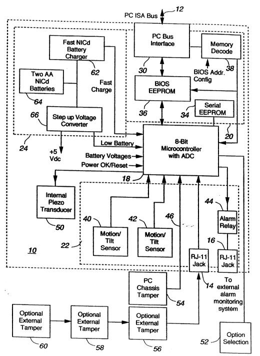
Referring to FIG. 1 there is illustrated in the block diagram a computer
security device in accordance with an embodiment of the present invention.
The computer security device includes a computer card 10 having a PC ISA
bus 12 and two RJ-11 jacks 14 and 16. The computer card 10 includes a
microcontroller 18, a computer subcircuit 20, an alarm subcircuit 22 and a
power subcircuit 24. The computer subcircuit 20 includes a PC bus
interface 30, a nonvolatile memory, serial EEPROM 34, a BIOS program
EPROM 36, and an address selector 38. The alarm subcircuit 22 includes
motion/tilt detectors 40 and 42, an alarm relay 44 connected to RJ-11 jack
21878~S
- 4 -
16, an input line connected to RJ-11 jack 14. In addition the computer card
includes an internal piezo transducer 50. Optional connection to an external
alarm monitoring system is provided through the RJ-11 jack 16. A PC
chassis tamper sensor 54 is connected via the line 46 and optional external
tampers 56, 58 and 60 are connected serially through the RJ-11 jack 14.
The microcontroller 18 on the computer card 10 provides secure and
independent firmware based access control. The microcontroller 18 also
provides a multi-channel analog to digital converter at a lower cost than
discrete components. The microcontroller 18 provides the following
1 0 functions:
Processing sensor lines as analog levels determining alarm and
tamper states;
Filtering of sensor inputs to provide a measure of false alarm
rejection;
Secure password verification in combination with BIOS
program;
Piezo transducer control, timed alarm blast, warning blast, low
battery chirp;
Read and act on option selection by jumper;
Drive external alarm system relay interface; and
Power supply monitoring.
An example of a suitable microcontroller is a Microchip 1 6C74
incorporating 4 Kbytes of ROM and 192 bytes of RAM, an onboard 8 input
8 bit ADC, parallel 8 bit slave port, PWM module, a power up timer, a
25 oscillator start-up timer, a watchdog timer, and communications ports.
The computer subcircuit 20 and the microcontroller 18 handle the
data security of the computer security device. In the computer subcircuit
20, the microcontroller 18 communicates with the PC ISA bus 12 via the PC
bus interface 30. The PC bus interface 30 includes the hardware interface
30 to the ISA bus in the computer, that is bus drivers and latches necessary for an ISA bus interface. The PC bus interface may be implemented, for
example by four 74ALS245 octal bus transceivers.
2187855
.
- 5 -
The serial EEPROM 34 stores security parameters and passwords for
secure access to the computer under the control of the microcontroller 18
and the BIOS EEPROM 36. The serial EEPROM 34 holds the current
password(s), security parameters associated with each level of password
5 and a real time count to support a limitation on password re-try. This
information is not accessible from the PC bus for security reasons. There
is no way to read out the password data from the PC under any
circumstances. An example of a suitable serial EEPROM is a 1024-bit
Microchip 24LC01 configured as 128x8.
The BIOS EPROM 36 provides the program used during start-up of the
computer to require the entry of a correct password and allows changing of
passwords and security parameters, depending upon the security level of the
password entered. The BIOS EPROM 36 is memory mapped so that it
executes upon boot-up of the computer. Its programming requires a basic
15 password entry sequence to be correctly completed before resuming and
completing the boot-up process. The code supports a password edit
function.
Using a BIOS program affords a high level of security because
execution of this code cannot be interrupted or bypassed by an informed
20 user. The BIOS program allows a hierarchy of several levels of operator,
each with different capabilities.
The address selector 38is used, prior to installation of the computer
card 10, to assign a computer device address for the computer card 10.
The computer device address, which must be unique within the computer,
25 ensures that the computer card 10 is addressed during the BIOS portion of
startup of the computer. The address selector 38 uses a jumper block to
enable the user to select different card addresses for compatibility with a
wide variety of computers and configurations. Address decoding may be
provided by, for example a Generic Array Logic (GAL) device, 16V8, that
30 decode the BIOS address into user selectable 4000 H segments starting at
C8000 H through DCOOO H.
The alarm subcircuit 22 provides the alarm sensor inputs to the
2187855
- 6 -
microcontroller 18. The motion/tilt sensors 40 and 42 are oriented
orthogonally to provide for either horizontal or vertical direction of the
computer. On initialization, the microcontroller 18 senses which switch is
"on" and which is "off". Any subsequent change in these state results in
5 an alarm condition. The alarm relay 44 is a form C relay contact closure and
is provided to interconnect the computer card 10 to a locally monitored
security system.
Tilt/motion sensors 40 and 42 detect tilting and course movements
of the PC chassis typical of those experienced during unit relocation, are
10 included on the circuit card. Two sensors are planned to detect movement
conveniently and tilt in two axes, respectively. Sensors 40 and 42 are
based on a mercury contact switch principle.
The PC chassis tamper sensor 54 is provided to ensure that access
to the computer hardware is detected. A combined switch contact-based
15 and mercury switch sensor is contemplated.
Two RJ-11 jacks 14 and 16 are accessible at the rear of the computer
for optional sensor or system interconnections. The first is provided to
connect to a series string of peripheral tamper sensors for protecting
keyboard, protector external devices. The second is the interface to an
20 external alarm monitoring system. The internal piezo transducer or
sonalert device is the main source of alarm indication once a sensor detects
an alarm condition.
The power subcircuit 24 includes a battery charger 62, two AA NiCd
batteries 64 and a step-up converter 66. The battery charger 62 is
25 connected to the +5V power lead of the PC ISA bus 12 and provides a
charge indicator signal to the microcontroller 18 and power to the NiCd
batteries 64 and to the step-up converter 66.
The battery charger 62 is included to re-charge the NiCd batteries 64
when the computer is in the AC on state. An example of a suitable battery
30 charger is a Benchmarq 2003.
The step-up converter 66 has a +5V DC output. The +5V DC
output powers the alarm card 10 when the computer is in an "off "
2187855
- 7 -
condition. The piezo or sonalert voltage, provided by a separate 9 V battery
(not shown in Fig. 1), powers the internal piezo transducer or sonalert when
the computer is in an "off" condition. The step-up converter 66 provides a
low battery indication signal to the microcontroller 18. The step-up
5 converter 66 steps the battery voltage from a nominal 2.4 V up to a higher
voltage of 5 V for digital component function during AC off operation. It
does not produce a higher voltage for the piezo transducer or sonalert.
Many of these devices require higher drive voltages to achieve the full sound
output level, hence a separate 9 V battery is provide for this purpose. An
10 example of a suitable step-up converter is a Maxim 856.
Two AA NiCd batteries 64 are included in a battery holder on the
computer card 10 for operation in the powered down state of the computer.
It is estimated that these batteries would operate the system for one month
1 5 without recharging.
The option selector 52 is in the form of option set-up jumpers. These
jumpers allow set-up of the features and modes of operation of the
computer security device. Selectable functions may include the following
features:
Hardware disable of the different sensor elements when they
are not used;
Long or short time limit on alarm audio (e.g., 5 min or 30 min.);
Silent operation, for those utilizing the alarm system
interconnect;
BIOS disable for those wanting only component security, not
data security;
Enable unsuccessful password (5) timeout feature, 30 min.
delay to retry;
For security reasons, these jumpers are only read by the
30 microcontroller upon entry of the highest level (Administrator) password,
thus preventing the possibility of a user or supervisor disabling the system.
These features are hardware keyed by the option selector 52 for some
2187855
.
- 8 -
installations. Many of these same features are security parameters
selectable as software options, as described hereinbelow in regard to Figs.
3a through 3e.
Operation of the computer security device of Fig.1 is described with
reference to Figs. 2a and b and 3a through e.
In operation, the microcontroller 18 when powered up performs
several actions as represented by the step chart of Fig. 2a. Once
operational, the microcontroller 18 performs several tasks as shown in Fig.
2b. As represented by step 1, the microcontroller 18 periodically measures
the external tamper sensor input, RJ-11 14 and reports any deviation via the
piezo transducer 50 and the alarm relay 44. An analog to digital converter
is provided in the microcontroller 18 for analog inputs. The A/D converter
digitizes alarm sensor input. The sensor input signal is then digitally filteredto reject false alarm conditions. As represented by step 2, the
microcontroller 18, via the analog inputs measures the battery voltages
under load when the computer is powered up or reset or when instructed to
do so by the BIOS program. As represented by step 3, the microcontroller
18, through inputs configured as state change interrupts for the
microcontroller, monitors the low battery indication from the step up
converter 66, the tilt/motion sensors 40 and 42, and chassis tamper sensor
54 and reports any deviation via the piezo transducer 50 and the alarm relay
44. As represented by step 4, the microcontroller 18, via the serial link 32
checks the status of the serial EEPROM as required, and may correct if
possible. As represented by step 5, the microcontroller 18, loads the serial
EEPROM with default parameters if instructed to do so by the BIOS program
or from hardware.
Referring to Figa. 3a through 3e there is illustrated a step chart a
method of securing a computer in accordance with an embodiment of the
present invention. The method relies upon password verification during
booting up of the computer, in particular the basic input output system
(BIOS) portion thereof, using the computer security device of Fig. 1.
As described hereinabove, the address selector 38 is set to provide
J 2187855
9
the computer security device, as embodied in the computer card 10, a
physical device address for the computer during BIOS boot-up. When the
computer card 10 is addressed an internal BIOS program, stored in the BIOS
EEPROM 36 is initiated, as represented by step 1.0 of Fig. 3a. The
remaining steps of the internal BIOS program are self-explanatory from Figs.
3a-3e.
While the present embodiment uses five (5) retries during password
entry and verification, this number may be chosen to be any desired number.
Preferably, a hierarchy of password protection is provided. For
example, a three-level password hierarchy has a user password level, a
supervisor password level, and an administration password level. Each level
of password has an associated capability set. For example, the following
capabilities may be associated with each password level:
1 5 User
This is a simple access code that, when correctly entered, allows the
normal processes in the computer boot sequence to complete. This access
code allows unrestricted use of the computing facilities but maintains the
integrity of the other security features. The user level only allows changing
the password. In the present embodiment a User password consists of a
four (4) alphanumeric characters.
SuPervisor
Entry of a password defined as supervisory level results in a simple
text based menu bar appearing. Available functions are:
Edit User or Supervisor password
Disable internal motion and peripheral sensors
Enable internal motion and peripheral sensors
Lists current sensor status, enable, disable, alarm and tamper
states
-- 2187855
- 10-
Continue boot sequence
When correctly entered, the internal motion/tilt sensors are disabled, until
' the computer is reset or turned off, at which time the sensors are re-
5 enabled. In the present embodiment a Supervisor password consists of a
five (5) alphanumeric characters.
Administrator
Entry of the Administrator level password results in a text based menu bar
appearing which has enhanced features. Available functions are:
Edit User, Supervisoror Administrator password
Disable internal motion & tamper and peripheral sensors
Enable internal motion & tamper and peripheral sensors
List current sensor status, enable/disable, alarm and tamper
~ states
View security system diagnostic reports
Change security parameters, such as number of peripheral
sensors, enable/disable of warning chirp, low battery chirp,
password entry and choosing password time-out period, alarm
duration, menu language
Continue boot up sequence
When correctly entered, the internal motion/tilt sensors are disabled, until
the computer is reset or turned off, at which time the sensors are re-
enabled. In the present embodiment a Administrator password consists of
a six (6) alphanumeric characters.