Note: Descriptions are shown in the official language in which they were submitted.
FAsTEr~G DEVICE ;2
D.N.41 -95
FIELD OF 'IHE I~VENTIO~
The present invention relates to fasteners in general and more particularly to
fasteners that are used to pull and secure two members together.
BACKGROUND OF 'I~IE INVENTION
There are a number of fasteners commercially available which are operable to pull
and secure together two members. for example two panels. The panels may be portable
enclosures, packing cases, instrument cases, transit cases, folding table. trunks, and other
packages, to narne a few. Generally, such fasteners consist of two separate elements,
each of which is att~ch~d to one of the panels. For inct~nre, one panel may be acont~iner lid and the other panel the con~iner body. Such fasteners may be used to
obtain a tight seal and may be used to Compless a gasket positioned between the two
panels. Examples of such f~cteners are disclosed in U.S. Patent Nos. 2,820,995,
2,853,751, 2,853,752, 4,090,727, and 4,746,151.
One particular problem observed with prior art fasteners is that many are large in
confilguration which severely limit the types of applications in which such fasteners can be
used. For inct~nre, such fasteners are not suitable for use in applications where there is
onl,~ a limited area in which the fastener can be mounted. Further, many such fasteners
are often times considered too "industrial looking" for use in applications where
appearance ~f the fastener is an illll)o~ consideration. For example, one such fastener
is shown in U.S. Patent No. 2,820,995 to Earnest Schleuter which describes a spring
loaded link lock 0 fastener comprising a hasp member 36 mounted on a spring member
31, which in turn is mounted to a bracket 16 secured to first panel 10. A slide plate
member 42 is received within the hasp member 36 which is extended or withdrawn by
rotation of a bolt 60, in order to engage a keeper 48 secured to a second panel 12 for
l~t~hing together of the respective panels. The spring member 31 in addition to f~ctening
the hasp member 36 to the bracket 16 also provides additional yielding force which
.~'
.. . . . .
2 ~ ~009
oper~tes to secure the panels in the latched position.
Another problem observed in prior art fasteners is that the amount of extension or
"grip range" of the fastener is limited. For example. in the U.S. Patent No. '.820~995
the hasp member 36 is adapted to be extended a specific amount by rotation of the bolt 60
for engaging the keeper ~8. Similarly. in U.S. Patent No. ~.090.7'7 to ~ier~n Busch
and Cuyler Hoen and reassi_ned to the ~csivn~e of the present invention. a hasp or slide
member 40 is provided which is extended a specific amount through rotation of three
interlocking disc members 50, 55. and 61 for eng~ging a keeper 10. However, in many
applications, the amount of extension or "grip range" provided by the hasp or slide
member is not sufficient. For instance~ one example is in applications where thicker
gaskets are desired to be utilized which would position the keeper beyond the "grip
range" of the latch.
Still another problem identified in the prior art is related to the mechanical
strength of the device. For example. in U.S. Patent No. 4,090,727, as noted above the
slide member 40 during operation is displaced through rotation of the three disc members
50, 55, and 61. In this configuration, the disc member 50 is positioned seated within an
opening 37 of a sleeve member 31 and is connected to the rem~ining two disc members
55, 61 by a rivet 70. In addition, the disc members 50 and 55 are each provided with a
boss exte~ ing from their upper surfaces and which extend into a corresponding openin~
in the disc members 55 and 61. respectively, for positioning the disc members relative to
each other. In operation the three disc members are rotatable about the rivet 70 in order
to extend or withdrawal the slide member 40. One disadvantage is that the disc member
50 may be dislodged from its seated position within the opening 37 of the sleeve member
31, reducing the overall strength of the latch and possibly leading to damage of the
various components or complete failure of the device. Further, another drawback is that
the rotation of the disc members in order to operate the latch can become more difficult
due to increased frictional resict~nce. Another disadvantage is that the lower disc
member 50 and middle disc member 55 may separate and release the connection between
the boss and co,~ )onding opening between the disc members also res-llting in latch
failure. Generally, such problems in latch operation can occur from excessive loads
2 1 88009
exerted on the device. for example. ~. hich can occur during operaliOn of the device as the
disc members are rotated or when under load. or from contact directly on the latch itself.
The present invention has been developed in view of the fore oing and to
overcome the deficiencies of the prior an.
SUMI~IARY OF T~IE I~VENTION
The present invention provides a fastener adapted to be secured to a firct member
for f~¢ening a keeper secured to a second member. In accordance with the presentinvention, the fastener comprises a base member, a sleeve member connected to the base
member, and a slide member received within the sleeve member to be extended or
withdrawn. The sleeve member is included with an opening into which a carn means is
received for rotatable movement. A cam member is also provided e~tentling from the
cam means and into a carn opening provided in the slide member. The fastener also
in~ des a turning means which is adapted to rotate the cam means so as to move the cam
member within the cam opening in order to extend or withdrawal the slide member. Tbe
f~cten~r may also include a biasing means confined within the base member in order to
bias the sleeve member relative to the base member as the slide member is f~ctenPA with
the keeper. In addition. the fastener may include means for increasing the amount of
extension or withdrawal of the slide member. Further. the fastener may include means
for re!~ ing the carn means within the opening provided in the sleeve member. The
fastener may also include a cam means of increased strength.
It is an object of the present invention to provide a novel fastener.
It is a another object of the present invention to provide a fastener of compactdesign and which provides a sufficient amount of force in order to secure two panels in a
latched position.
It is another object of the present invention to provide a fastener having increased
"grip range" of its slide member.
2~ &8009
It is still another objecl of the presem invemion to provide a tastenef which isadapted to retain a cam mechanism in a seated position within a sleeve member during
operation.
It is still another object Ot the present invention to provide a tastener having a cam
nlecll~nicrn of increased stren_th and durability.
These and other objects or the present invention will be more readilv apparent
from the following description and ~tt~ched drawings.
BRIEF DESCRIPI'ION OF THE DRAWINGS
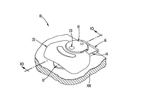
Fig. 1 is a perspective view of a fastener in accordance with an embodiment of the
present invention, shown mounted to a ponion of a panel.
Fig. 2 is an exploded view of the fastener shown in Fig. 1.
Fig. 3 is a front view of a sleeve member shown in Fig. 2.
Fig. 4 is a top plan view of a first disc member of Fig. 2.
Fig. 5 is a left side elevational view of the first disc member of Fig. ~.
Fig. 6 is a top plan view of a second disc member of Fig. 2.
Fig. 7 is a left side elevational view of the second disc member of Fig. 6.
Fig. 8 is a top plan view of a third disc member of Fig. 2.
Fig. 9 is a left side elevational view of the third disc member of Fig. 8.
Fig. 10 is a sectional view of the fastener of Fig. 1 taken along the line 10-10.
Fig. 11 is an embodiment of a keeper adapted to be engaged by the fastener of
Fig. 1.
Fig. 12 is an exploded perspective view of a fastener in accordance with anotherembodiment of the present invention.
Fig. 13 is a top plan view of a second disc member of Fig. 12.
Fig. 14 is a left side elevational view of the second disc member of Fig. 13.
Fig. 15 is a bottom plan view of a third disc member of Fig. 12.
Fig. 16 is a left side elevational view of the third disc member of Fig. 15.
Fig. 17 is a fastener in accordance with another embodiment of the present
invention.
21 &8009
Fi 18 is a tOp plan vieu of a first disc member of Fig. 17.
Fig. 19 is a sectional view of the fastener of Fig. 17 and is taken along a line 10-
10 shown in Fig. 1.
Fig. 20 is a top plan view ot' another embodimem of a first disc member of Fig.
17.
Fig. 21 is a left side elevational view of the first disc member ot' Fig. '0.
Fig. 22 is a top plan view of another embodiment of the first disc member of Fig.
17.
Fig. 23 is a left side elevational view of the first disc member of Fig. 22.
Fig. 24 is a bottom plan view of another embodiment of a first and second disc
member of Fig. 17.
Fig. 25 is a left side elevational view of the first and second disc member of Fig.
24.
Fig. 26 is a top plan view of the first and second disc member of Fig. 24.
Fig. 27 is bottom plan view of another embodiment of the first and second disc
member of Fig. 24.
Fig. 28 is a left side elevational view of the first and second disc member of Fig.
27.
Fig. 29 is a top plan view of the first and second disc member of Fig. 27.
Fig. 30 is a side elevational view of a fastener in accordance with another
embodiment of the present invention. shown mounted to a panel.
Fig. 31 is a top plan view of a base member of Fig. 30.
Fig. 32 is a side elevational view of the base member of Fig. 31.
Fig. 33 is a sectional top plan view taken along the line 33-33 of Fig. 30.
Fig. 34 is a front elevational view of a biasing means of Fig. 30.
Fig. 34a is a right side elevational view of the biasing means of Fig. 34.
Fig. 35 is a sectional front elevational view taken along the line 35-35 of Fig. 30.
Fig. 36 is a top plan view of another embodiment of a biasing means of Fig. 30.
Fig. 37 is a sectional side elevational view taken along the line 37-37 of Fig. 36.
Fig. 38 is a top plan view of another embodiment of a biasing means of Fig. 30.
Fig. 39 is a sectional side elevational view of the biasing means of Fig. 38.
Fig. 40 is a top plan view of another embodiment of a biasing means of Fig. 30.
21 ~8009
Fig. ~1 is a sectional side elevationai ~iew laken along the line 41-~1 of Fig. ~0.
Fig. 42 is a top plan view of anolher embodiment of a biasing means of Fig. 30.
Fig. 43 is a sectional side elevational view ot' the biasing means of Fi 42.
Fig. 41 is a top plan view of another embodiment of a biasing means ot' Fig. 30.Fig. 15 is a sectional side elevational ~iew of the biasing means of Fi~
Fig. 46 is a top plan v iew of another embodiment of a biasing means of Fig. 30.Fig. ~7 is a sectional elevational view of the biasing means taken along the line
47-47 of Fig. 46.
Fig. 48 is an embodiment of a base member adapted to receive the biasing means
of Fig. 46.
Fig. 49 is an exploded perspective view of a fastener in accord~nce with anotherembodiment of the present invention.
Fig. 50 is a top plan view of a base member of Fig. 49.
Fig. 51 is a front elevational view of a biasing means of Fig. 49.
Fig. 52 is a top plan view of the biasing means of Fig. 51.
Fig. 53 is a sectional side elevational view of the fastener of Fig. 49 and taken
along the line 10-10 of Fig. 1.
Fig. 54 is a top phn view of another embodiment of a biasing means of Fig. 49.
Fig. 55 is a sectional side elevational view taken along the line 55-55 of Fig. 54.
Fig. 56 is a front elevational view of the biasing means of 54.
DETAILED DESCRIPTION OF THE PREFERRED E~IBODIMEl~TS
Referring now to the drawings in detail. wherein like reference numerals indicate
like elements throughout the several views, there is shown in Fig. 1 a perspective view of
a f~ctener in accordance with one embodiment of the present invention. The fastener 10
as shown includes, as portions thereof, a base member 12, a sleeve member 14, a slide
member 16, a cam means 18, a cam member 20, and a turning means 22. The portionsof the fastener 10 will be described in more detail in the following paragraphs.
As shown in Fig. 1, the fastener 10 is adapted to be connected to a first member100. As in-lic~ttoA earlier. the first member can comprise a panel, closure or the like,
2 1 ~8009
such as the body portion of a container. The attachment of the fastener 10 to the first
member 100 is accomplished bv the base member 12. The base member 1' is ~ttached to
the first panel 100 by means of screws or other suitable fastener. such as an adhesive. As
best seen in the exploded view of Fig. 2. in the present embodiment. the base member 12
includes a bottom plate having holes 24 therethrough for attachment to the first panel 100
by a pair of screws (not shown). The base member 12 may also have opposing side
portions 26 and 28 at respective opposite sides of the bottom portion of the base member
12. The side portions 26 and 28 each have a hole therethrough, respectively 30 and 32,
through which an elongated pin 34 is secured. The pin 34 in the present embodiment has
a head at one of its ends. positioned on the outside of the side portion 26. and a peened-
over portion, positioned on the outside of the opposite side portion 28.
The sleeve member 14 has, as integral portions thereof, an upper surface 38, a
lower surface 40, a central portion 42 and a connecting portion which, in the present
embodirnent, comprises a turned-over elongated tubular portion 44. The shank of the pin
34 fits within the tubular portion 44 so that the sleeve member 14 is hinged and rotatable
about the pin 34. Hinge means comprising the pin 34, and tubular portion 44 permits
pivotal motion of the sleeve member 14 relative to the base member 12.
As best illustrated in the front view of Fig. 3, the sleeve member 14 also includes
a sleeve, which in this embodiment is comprised of two turned-over side edge flanges
forming sleeve portions 46 and 48 on its opposite sides. the internal faces of which form
a guide way. As shown in Fig. 2, the sleeve member 14. at its centIal portion 42,
in~ludes a central circular opening SO therethrough which, in the present emboliimpnt~ is
cenlc~c;d at a raised boss portion 52 and has an im~,in~ry center. The sleeve member 14
also may include a channel 53 in its lower surface 40 extending from the opening SO to
the front end thereof, as is best seen in Fig. 3.
The slide member 16 fits and slides within the two side sleeve portions 46 and 48
of the sleeve member 14. The slide member 16 may be moved longit~l-lin~lly within the
slide formed by the sleeve portions 46 and 48. As shown in Fig. 2, the slide member 16
is a generally rectangular member which is subst~nti~lly ra~iused at one end to forrn a
-
2 1 880û9
hook-like lip portion 5~ The flat portion Ot the slide member 16 has an elon ated cam
opening 56 therethrough. .~ second Qenerally U-shaped opening 58 mav also be provided
through the flat portion of the slide member 16 which forms a Rexible and resilient
tongue 60 having a small raised boss 6~ adjacent its end. The boss 6~ rides within the
channel 53 as the slide member 16 is moved lon_itudinallv within the sleeve member 14
The cam means 18 is received within the opening 50 of the sleeve member 14 for
rotatable movement therein. and the cam member 20 extends from the cam means 18 and
into the cam opening 56 of the slide member 16. the details of which will be more fully
described below.
The turning means 22. in this embodiment. comprises a handle having inwardly
protruding and opposed fingers 64 and 66 which are subsl~..l;~lly square in cross-section
and fit within the carn means 18, in the manner hereinafter described. for providing
rotation of the cam means 18.
In accordance with the present invention, the carn means 18 preferably comprisesat least one disc member. such as the type in U.S. Patent Nos. 2,820.995 and 2,853,751
or, more preferably, two or more disc members, such as the type in U.S. Patent No.
4.090,727 in which a series of three stacked and interconnected disc members areprovided. For purposes of illustration. in the presenl embodiment the cam means 18 is
shown in Fig. 2 comprising the three disc members 68, 70 and 72.
The first disc member 68 as is shown in Fig. 4 is round in top view and its
diameter is preferably slightly less than the di~met~r of the opening 50 in the sleeve
member 14 in order to be fit within the sleeve member opening 50. The first discmember 68 preferably has a pair of holes 74 and 76 and a small protruding boss 78. In
addition, the first disc member 68 may also include an optional indent~tion 80 on its side
opposite boss 78 and aligned therewith, as shown in dotted line in the side view of Fig. 5.
In this embodiment. the boss 62 on tongue 60 of the slide member 16 removably fits in
hole 76 as a detent when the slide member 16 is withdrawn. As shown in Fig. 4, the
hole 76 is round in shape and extends through the disc member 68, however, the hole 76
2 1 88009
can also comprise an indentation which does not extend through the disc member 68.
Also. the position of the hole 76 may valv depending on the position of the boss 62 of the
slide member 16 or. alternatively. the hole 76 may be elimin~tPcl where the boss 62 is no
provided or the boss 62 may be adapted to engage the indentation 80 so that the hole 76
is not required. In addition. the hole 71 in the present embodiment is substantially round
in configuration. however. it should be understood that other shapes of tlle hole 74 can
also be utilized.
The second disc member 70 as shown in Fig. 6 is also round in top view and
preferably has a slightly largely diameter than the diameter of the first disc member 68.
In this embodiment, the second disc member 70 rides on top of the boss 52 of the sleeve
member 14 and not within the opening S0. The second disc member 70 has a hole 82which is of the same configuration as the hole 74 in the present embodiment. however,
this is not lecluir~d. The second disc member 70 also is in~ ded with a small raised boss
84 and a small in-lent~tion 86 behind the boss 84, as shown in dotted line in the side view
of Fig. 7. The boss 78 of the first disc member 68 fits within the in~lPnt~tion 86 of the
second disc member 70. Alternatively, the small inderlt~tic)n 86 can also comprise a hole
e~ctenfling completely through the second disc member 70. The second disc member 70
as shown in Fig. 6 also inclu(les opposile side in~lentations 88 and 90 into which are
received the fingers 64 and 66 of the turning means 22.
The third disc member 72 as shown in Fig. 8 is preferably of a sufficiently
flexible material such as spring metal. for example. sheet metal of spring steel. and
includes a hole 92 which, in the present embodiment, is of the same diameter as the holes
74 and 82, however, this is not required. The third disc member 72 also includes a
smaller hole 94 or, alternatively an inclent~tion, which the boss 84 of the second disc
member 70 fits. In addition, preferably the third disc member 72 is bent slightly along
its central axis between the holes 92 and 94, as is best seen in the side view of Fig. 9.
The third disc member 72 holds the turning means 22 in position and exerts spring
pressure on the subst~nti~lly square fingers 64 and 66 to tend to restore the turning means
to either a flat or raised position.
2188009
- .
The interloclcinP ot the three disc members 68. ,0 and 72. so that they rotate
together as a unit. is accomplished by the bosses 78 and 84 v. hich fit in indent~tion 86
and hole 94. respectively. as is shown in the sectional ~iew of Fig. 10 taken alon~ the
line 10-10 of Fig. 1.
The cam member 20 as shown in FiV. ' in the present embodiment comprises a
rivet having a head 98 and a generally elon~ated shank 104. As best seen in Fig. 10, the
enlarged rivet head 98 is sufficiently large so that its diameter is greater than the width of
the elongated cam opening 56 of the slide member 16, which prevents the rivet from
being pulled through the opening 56. The shank 104 of the rivet protrudes through the
opening 56 and also protrudes through the aligned holes 74. 82 and 92 through the three
disc members. The top of the rivet opposite the head 98 is peened-over and forms an
enlarged head above the hole 92 in the third disc member to hold the three disc members
68, 70 and 72 together. When the turning means 22 is rotated, the cam member 20 will
move within the cam opening 56 of the slide member 16 and rotated about the ima~in~ry
center of the ol)ening 50 of the sleeve member 14, which will extend or withdrawal the
slide member 16 a predetermined amount, as will be described in detail below. Asshould be understood, the cam member in accordance with the present invention may also
be secured to the first disc member without also extçn-iing through it where, for example,
the cam member is not required for connection of the disc members or where only one
disc member comprises the cam means.
The portions of the fastener 10 described above may be manufactured by
conventional techni~ es and of commercially available materials, such as stamped from
sheet metal.
In acco.dance with the present invention. means are provided for increasing the
predetemmined amount of extension or withdrawal of the slide member 16. In the present
embodiment, the increasing means is provided through the interaction of the first disc
member 68 and the cam member 20. Specifically, the hole 74 through the first disc
member 68 is positioned closer to the perimeter than to the center of the first disc
member 68 which, in tum, also positions the shank 104 of the cam member 20 closer to
2 1 88009
the perimeter of the first disc member 68 than to its center. The operation of which will
be described in the following paragraph.
In operation, starting with the slide member 16 in its extended position, the sleeve
member 14 is rotated about the hinge means in order for the hook-like lip portion 54 of
the slide member 16 to come into engagement with a keeper 102, which is secured to a
second member 103, for example, the second member 103 may be a portion of a lid of a
cont~iner. As is shown Fig. 11, the keeper 102 comprises a keeper plate portion which is
secured to the second member 103 by suitable f~ctening means and a curved turned-over
hook-like keeper lip portion. In this embo~limçnt, the flat keeper plate portion is provided
with two holes therethrough in order for f~ctening to the second member 103 by means of
screws or other f~ctening devices. The keeper 102 may also comprise an extrusion or
other shaped keeper. Aher the slide member 16 engages the keeper 102, the turning
me~ans 22 is rotated clockwise, if viewed looking directly down upon the latch. The carn
member 20 is also turned clockwise about the im~gin~ry center of the three disc
mem~rs, with the disc members being aligned so that their centers lie on a common
im~in~ry line. The rivet shank 104 of the cam member 20 pushes on the cam opening
56 and cams the withdrawal of the slide member 16 within the guide-ways of the sleeve
portions 46 and 48 of the sleeve member 14. At the end of the tun~ing motion, the slide
member 16 is completely withdrawn in the position illustrated in Fig. 10 and the boss 62
of the slide member 16 moves into the in~ent~tion 78 of the first disc member 68. Due
to the position of the rivet shank 104 being closer to the perimeter than to the center of
the first disc member 68, the ~ict~nt~e of travel of the slide member 16 within the guide-
ways of the sleeve portions 46 and 48 is increased as the slide member 16 is moved by
the cam member 20 into the completely withdrawn position from its extended position.
In the completely withdrawn position, the hook-like end portion of the keeper 102 is
fastened with the hook-like lip portion 54 of the slide member 16.
To unlock the fastener 10 the operation is reversed, specifically, the tu~ing means
22 is rotated counterclockwise, thus causing the rivet shank 104 of the cam member 20 to
rotate and thereby cam the slide member 16 to its extended position and also turn the
in~nt~tion 78 away from the boss 62. Similar to the locking procedure noted above, due
21 ~8009
-
to the position of the rivet shank 104 bein~ closer tO the perimeter than to the center of
the first disc member 68, there is an increase in the distance of travel of the slide member
16 within the sleeve ponions 46 and 48 as the slide member 16 is moved by the cam
member 20 into its e.Ytended position from its completely withdrawn position.
Another example of a multiple disc member cam means in relation to the fastener
10 is illustrated in Fig. 12. In this embodiment, the cam means 18 is shown comprising
the three disc members 68A, 70A and 72A. The first disc member 68A as shown
corresponds in configuration to the disc member 68 set forth above and will not be further
described herein for this reason.
The second disc member 70A as shown in Fig. 13 is preferably of a sufficiently
flexible material, such as sheet metal of spring steel, and includes a slot 82A therethrough
which, in this embodiment, is suhst~nti~lly radiused in configuration. The slot 82A in
operation corresponds to the hole 82 of the disc member 70 described above for receiving
the cam member. The second disc member 70A also includes a se~ ond slot 86A which is
substantially radiused in configuration is this embodiment. The slot 86A corresponds to
the inrient~tion 86 of the disc member 70 in its operation for receiving the boss exten-lin~
from the first disc member. The second disc member 70A preferably also includes a hole
84A round in shape and a pair of opposile side extensions 88A and 90A subst~nti~lly
square in shape. In addition, preferably the second disc member 70A is bent slightly
along its central axis bisecting slots 82A and 86A, as is shown in the side view of Fig.
14.
The third disc member 72A as shown in Fig. 12 is round in top view and includes
a hole 92A therethrough which is round in shape in this embodiment and which
corresponds to the hole 92 of the disc member 72 described above for receiving the cam
member. The disc member 72A also includes a downwardly extenlling flange 43A at its
perimeter which includes a pair of opposite side in~ientations 88B and 90B (only 90B is
visible in Fig. 12) which are subst~nti~lly square in shape in this embo~im~nt, into which
fit the subst~ntially square fingers of the turning means and side e~lensions 88A and 90A
of the second disc member 70A. The side infi~nt~tions 88B and 90B of the third disc
12
2 1 88009
member 72A holds the turning means in position and the side extensions 88A and 90A of
the second disc member 70A exerts spring pressure on the substantially square fingers to
tend to restore the turning means to either a flat or raised position. The third disc
member 72A is also included with a small raised boss 94A exten~ling from its lower
surface which fits within the hole 84A of the second disc member 70A, as is shown in the
bottom and side views of Figs 15 and 16.
The interlocking of the three disc members 68A, 70A and 72A so that they rotate
together as a unit, is accomplished by the boss 78A of the first disc member 68A and the
boss 94A of the third disc member 72A which fit in slot 86A and hole 84A of the second
disc member 70A, respectively. The rem~ining operation of the three disc members 68A,
70A and 72A corresponds to that described above with respect to the disc members 68,
70 and 72.
Another aspect of the present invention is to provide means for ret~ining a cam
mech~ni~m within the opening of a sleeve member as the carn mech~ni~m is rotated. In
order to illustrate this feature of the present invention, reference is made to Fig. 17 which
illustrates an exploded perspective view of a fastener 110 which incorporates one
embodiment of a cam means in accoldanoe with the present invention. For reasons of
clarity, the portions of the fastener 110 which col~ ond to portions described in relation
to the fastener 10 will b~, described using the same number ~esign~tions beginninE with
100. Similar to that described above in relation to the fastener 10, the cam means in
accordance with this aspect of the present invention preferably comprises at least one disc
member and, more preferably, two or more disc members, such as the types illustrated in
Figs. 2 and 12. As sho~vn in Fig. 17, for purpose of this illustration the cam means 118
comprises the three disc mçrnbers 168, 170 and 172 which are similar to the discmembers 68, 70 and 72 described in relation to the fastener 10. The differences in the
disc members 168, 170 and 172 are in the configuration of the first disc member 168 and
the positions of the holes 174, 182 and 192 which receive the cam member 120.
Specifically, the first disc member 168 in this embodiment is provided having means for
en~aging the lower surface 140 of the sleeve member 114 proximate the opening 150 of
the sleeve member 114 when the disc member 168 is mounted. As illustrated in Fig. 17,
2 1 8800~
the eng~ging means in this embodiment comprises a flange 175 which extends radially
outward from the perimeter of the first disc member 168 adjacent its lower disc surface.
Preferably, the flange 175 extends a predetermined amount around the perimeter of the
first disc member 168 and, in the present embodiment, the flange 175 as shown in the top
plan view of Fig. 18 extends entirely around the perimeter of the first disc member 168.
The flange 175 defines an area of increased diameter of the first disc member 168, which
operates to retain the cam means 118 within the opening 150 of the sleeve member 114
through its engagement with the i~side edge of the cam opening 150 and the sleeve lower
surface 140. Specifically, as shown in the section~l view of Fig. 19 taken along the same
line shown in Fig. 10, an upper surface 177 of the flange 175 is positioned adjacent, but
not necessarily in engagement with, the lower surface 140 of the sleeve member 114
when the cam means 118 is mounted. In this embodiment, as shown in Fig. 17,
mounting is accomplished by inserting the first disc member 168 up from the bottom of
the sleeve member 114 and through the opening 150 from the direction of the lower
surface 140 to the upper surface 138. Similar to that described above in relation to the
fastener 10, the three disc members 168, 170 and 172 are intel~onnected by the cam
member 120 extPn-ling through the aligned holes 174, 182 and 192 extending through the
disc members. Further, in the present embodiment, as shown in Fig. 18 the position of
the hole 174 for the first disc member 168 is closer to the perimeter than to the center of
the disc member 168, however, it should be understood that this is not required.Specifically, the position of the hole 174 through the first disc member 168 can be
provided at any location: for instance, at any position extending from the center to the
perimeter of disc member 168. Similarly, the same would apply with respect to the
rem~inin~ disc mPmbers 170 and 172 which are positioned so as to be aligned with the
hole 174 e~en~ling through the first disc member 168. In addition, as indicated earlier in
relation to the first disc member 68. the position of the hole 176 may also be varied or
alternatively elimin~tecl in the first disc member 168.
In operation, the upper surface 177 of the flange 17~ is adapted to engage the
lower surface 140 of the sleeve member 114 which m~int~inc the position of the cam
means 118 and also acts as a bearing surface. As indicated earlier, in prior art devices,
the first disc member can be dislodged from its position within the slide member when
21 8~009
the latch is under load. Generally, in the prior art devices, dislodgement of the first disc
member was found to most likely occur at the end opposite of the location of the cam
member. In the present invention, the engagement between the flange 175 and the lower
surface 140 of the slide member 114 will prevent dislodgement of the first disc member
168 in situations where dislodgement would have occurred in the prior art devices.
The rem~ining portions and operation of the fastener 110 is the same to that
already recited in connection with the fastener 10 and, for the sake of brevity, will not be
described in co~nection with the present embodiment.
In Figs. 20 and 21 is shown a second embodiment of a first disc member in
relation to the fastener 110. In this embodiment, the first disc member 268 is provided
with a single tab 275 which extends only partly around the perimeter of the first disc
member 268 and is positioned generally opposite the hole 274. As is shown, the tab 275
ten~ls approximately 45 degrees around the perimeter, however, it should be understood
that the tab 275 can extend either less or more around the perimeter of the first disc
member 268. Further, in the present embodiment, the position of the tab 275 is generally
opposite the hole 274 since, as in~icate~ earlier, dislodgement of the first disc member in
prior art devices is most likely to occur at the position of the disc member opposite the
cam memher. It should be understood, however, that the tab 275 can be provided at
other locations along the perimeter of the first disc member 268 where desired. Further,
in the present embodiment the tab 275 is shown being generally radiused in shape,
however, Ws is not required and the tab 275 may also be provided of other
configurations as well.
In Figs. 22 and 23 is shown still another embodiment of a first disc member in
relation to the raslener 110. In Ws embodiment, two tabs 375 and 376 are provided
e~ct~n~ling from the perimeter of the first disc member 368 generally opposite the hole
374. As shown, the tabs are spaced generally 45 degrees apart and are substantially
squ~re in configuration. In the present embodiment, while two tabs 375 and 376 are
shown, it should be understood that any number of tabs can be provided for the same
purpose, for exarnple 1, 2, 3, etc. Also, the tabs can be of any particular size or
2 1 88009
configuration, and positioned at any desired location or spacing from each other along the
perimeter of the disc member. For example, three tabs can be provided, with the first and
third tabs spaced approximately 180 degrees from each other and the second tab
positioned generally between the first and third tabs and opposite the cam member.
Further, the first and third tab members mav be configured similar to the tabs 375, 376
and the second tab member can be configured corresponding to the tab 275 It should be
understood that this example is given for illustration purposes only and in no way limits
the number of possible variations.
Mounting of the first disc members 268 and 368 described above may be
accomplished in the same manner as the first disc member 168 which is up from the
bottom of the sleeve member or, alternatively, downward into the sleeve member where
possible depending on the particular configuration of the tab portions.
As indicatecl earlier, another aspect of the present invention is to provide a cam
me~h~nicm of increased strength and durability. Specifically, in prior art devices where
more than one disc member is provided, such as in U.S. Patent No. 4,090,727, the disc
members can separate and di~connect from one another when the latch is under load,
possibly leading to failure of the device. For purpose of illustration, the present feature
will be described in relation to the fastener 10. With reference to Fig. 2, in accordance
with one embodiment, a cam means 418 is provided bv the combination of the third disc
member 72 with a disc member 468 which is in place of the disc members 68 and 70.
Advantageously, the disc member 468 is of one-piece in construction which over~o.~,es
the problems of the prior art in which multiple disc members would separate and
disconnect from one another. The specific configuration of the disc member 468 is best
seen in Figs. 24-26. In this embodiment, the first disc member 468 defines a lower disc
469 and an upper disc 471 which are integrally connecte~l to each other.
The lower disc 469 as shown in Fig. 24 is sllbst~nti~lly round in bottom view and
includes a hole 474 for receiving the cam member and an indentation 476. As shown in
Figs. 24 and 26, the hole 474 is subst~nti~lly round in configuration, however other
shapes may also be provided. The indent~tion 476 as shown may also coM~,.ise a hole
16
. .
- 2 1 88009
extending completely through the lower disc 469 or alternatively may be deleted. In this
embodiment, the boss on the tongue of the slide member removably fits in inr~e-ltation
476 as a detent when the slide member is withdrawn.
The upper disc 471 as shown in Fig. 26 is round in top view and. in this
embodiment, its diameter is greater than the diameter of the lower disc 469. The upper
disc 471 also includes a subst~nti~lly round cavity 489 through its mid section which
extends to the lower disc 469. In this embodiment, the upper disc 471 also includes four
support members 490 within its cavity 489 and engaging the lower disc 471 for
reinforcing the co~n~ction therebetween. The lower disc 469 as shown in Fig. 24 also
includes four inrlPntations 492 generally opposite the position of the four support members
490, however, the indentations 492 may be deleted where desired. The upper disc 471 is
also included with a pair of opposite side indent~tions 488B and 490B which, in this
embodiment, are substanti~lly square in shape and receive the subst~nti~lly square fingers
of the turning means. The disc member 468 can be manufactured by con~enlional
techniques and of commercially available materials, such as being extruded from metal.
In this emboc~iment, the hole 94 through the disc member 72 shown in Fig. 2 is not
required and may be deleted.
Mo~nting of the disc member 468 in this embodiment is accomrliche~i by insening
the lower disc 469 downward into the opening of the sleeve member until the upper disc
471 comes into engagement with the upper surface of the sleeve member. The rem~ining
operation is the same as that described earlier.
The cam means 418 in accordance with the present invention may also incorporate
one or both of the features described above; namely, means for increasing the
predete,~,-ined amount of extension or withdrawal of the slide member or means for
ret~ining the cam means within the opening of the sleeve member. Similar to thatdescribed above in relation to the factener 10, the increasing means can be provided
through the interaction of the cam membçr with the hole 474 through the lower disc 469;
in par~ticular, the position of the hole 474 being provided closer to the perimeter of the
lower disc 469 than to the center of the lower disc 469. In ad~liti~n~ the ret~inin~ means
2 ~ 8800q
-
can be provided through the interaction of the disc member 468 with the sleeve member,
similar to that described in relation tO the fastener 110. For purpose of illustration only,
in Figs. 27-29 is shown a disc member 468A which incorporates each of the foregoing
features. As should be understood, alternative embodiments may incorporate either one
of the two features hereinafter descnbed.
The lower disc 469A in this embodiment includes a single tab 475A which extends
only partly around the perimeter of the lower disc 469A and is positioned generally
opposite the hole 474A. It should be understood however that while a single tab 475A is
illustrated, one or more tabs can be provided of any desired configuration and positioned
at any desired location along the perimeter of the lower disc 469A, such as that described
above in relation to the disc members 268 and 368. In the present embodiment, the
interaction of the tab 475A with the bottom surface of the sleeve member operates to
retain the cam means 418A within the sleeve member opening. In addition, the
interaction of the upper disc 471A with the sleeve member provides an additionalmerh~nicm for ret~ining the position of the cam means 418A. Specifically, as shown in
Fig. 28 the lower surface 473A of the upper disc 471A is adapted to come into
engagement with the upper surface of the sleeve member as the cam means 418A is
rotated. Fu~her, as illustrated in Fig. 29, in the present emhodimP-nt the upper disc 471A
is provided with an inrl~nt~tion 491A adjacPnt the tab 475A, however it should be
understood that the in-~ntation 491A may be deleted where desired.
As shown in Figs. 27 and 29, the increasing means in this embodiment is providedby the lower disc 469A which includes a hole 474A positioned closer to the perimeter
than to the center of the lower disc 469A. In addition, the top disc member which is
illustrated by the disc m~mber 72 in Fig. 2 is accordingly provided with a hole 92 which
is positioned so as to be aligned with the hole 474A in order to accommodate receiving
the cam mPmhPr through each of the holes 474A and 92, respectively. As indicatedearlier, the inte.~.;lion of the cam member and the lower disc 469A provides an incrreased
amount of extension or withdrawal of the slide member as the cam means 418A is
rotated. The renl~ining features of the disc member 468A are the same as that recited
above with respect to the disc memh~r 468.
18
2 1 8800'~
Another aspect of the present invention is to provide a fastener of compact design
so that the fastener may be mounted in smaller areas but which will still provide suf~lcient
force in order to properly latch. In accordance with this feature of the present invention,
in Fig. 30 there is shown a side view of one embodiment of a fastener 510. Fastener 510
as shown includes, as portions thereof, a base member 512, a sleeve member 514, a
biasing means 515, a slide member 516, cam means 518, a cam member 520, and turning
means 522. In the present embodiment, the structure and operation of the slide member
516 and turning means 522 are the same as that described in relation to the fastener 10
and will not be described further herein for this reason. The cam means 518 and cam
member 520 may comprise any of the cam means 18, 118, 218, 318 or 418 and
associated cam members described above, or any prior art arrangements which are
adapted for this purpose, such as that described in the prior art patents noted earlier in the
background of the invention. For purposes of illustration, in the present embodiment, the
cam means 518 coll~s~onds to the cam means 218 and will not be described in further
detail for this reason.
The base member 512 as shown in the top view of Fig. 31, includes extending
upward from its bottom portion at least one and preferably two bosses 517 and 519. The
bosses 517 and 519 may also include a subst~nti~lly annular hook-shaped end portion, as
is shown in dotted line in the side view of Fig. 31 (only 519 is visible). In the present
embodiment, the bosses 517 and 519 are generally rectangular in shape and are formed
from a bent up section of the bottom portion of the base member 512. However, bosses
517 and 519 can be provided having any desired shape, or as separate members which are
7,tt~0hed to the bottom portion of the base member 512. In addition, any number of
bosses can be provided for the same purpose. The base m~mber 512 further includes two
in~linP~ generally elongat~d shaped-slots 530 and 532 provided through the opposing side
portions 526 and 528, respectively. In the present embodiment, the slots 530 and 532
extend with a downward slant of approximately 40~ to the bottom portion from near the
upper corners toward the front end. However, the slots 530 and 532 may be incline~ at
any desired angle; a preferable range is between 30~ and 50~.
19
21 88009
As shown in the sectional view of Fig. 33 taken along the line 33-33 of Fig. 30,the sleeve member 514 is pivotally connecte~ by hinge means to the base mçmber 512.
Similar to that described above in relation to the fastener 10, the hinge means COlllpli~S a
pin 534 and tubular portion 544 of the sleeve member 514. Further, the pin 534
preferably includes a head 536 at one of its ends and a peened-over portion 536A at the
opposite end, which are each positioned on the outside of the opposing side portions 526
and 528 through the slots 530 and 532 of the base member 512. In a~ ition~ the pin 534
is received within the tubular portion 544 for connection of the sleeve member 514. In
this embodiment, the tubular portion 544 does not extend the entire width of the sleeve
member 514, which is different from the arrangement with respect to the tubular portion
44 of the sleeve member 14. In particular, each of the opposing side portions of the
sleeve member 514 step inwardly proximate the tubular portion 544 which define
substantially square-shaped openings 550.
As shown in Fig. 34, the biasing means 515 in the present emt~1iment comprises
a torsion spring preferably co,..p-ised of metal, such as stainless steel, although other
suitable materials may also be used. The torsion spring 515 in the present embodiment
preferably comprises two wound portions 521 and 523, a generally U-shaped section 525
exten~linE between the wound portions 521 and 523, and a pair of end sections 527 and
529 e~ten~iinE from the opposite ends of the wound portions 521 and 523. Although not
shown, it should be understood that variations in the torsion spring 515 may be provided,
such as providing a difre~ent configuration of torsion spring, varying the number of
wound portions, varying the number of windings in each wound portion, to name a few.
The primary concideration is that the torsion spring 515 when mounted will be positioned
suhst~nti~lly within the exterior boundaries of the base m~mber 512, an example of which
is illuctrated in the present embo~liment
As illustrated in the sectional view of Fig. 35 taken along the line 35-35 of Fig.
30, the pin 534 when mounted fits within the two wound portions 521 and 523 and the U-
shaped portion 525 is in engagement with the two bosses 517 and 519 extending upward
from the bottom portion of the base member 512. As best seen in Fig. 33, the twowound portions 521 and 523 are positioned within the s~bst~nti~lly square-shaped
21 88009
-
openings 550 of the sleeve member 514. As shown in Fig. 35, preferably the opposing
end portions 527 and 529 of the torsion spring 515 extend in the direction of the front of
the base m~mber 512, and also may be positioned so as to bias against the opposing side
portions 526 and 528 and the bottom portion of the base member 512. Further, the end
portions 527 and 529 may also be slightly bent at its termin~ting ends, as shown in the
side view of Fig. 34a.
When the fastener 510 is in an Iml~tch~l position, preferably the pin 534 is
positioned against the upper most ends of the slots 530 and 532 near the upper corners of
the base member 512, as illustrated in Fig. 30.
In operation, when the fastener 510 is latched with the keeper, the force of thetorsion spring 515 is adapted to provide an additional l~tching force in order to secure the
panels together. As the slide m~mber 516 is withdrawn and latched with the keeper, the
pin 534 preferably moves against the bias of the torsion spring 515 downward in the slots
530 and 532 in the direction of the bottom portion of the base member 512. The wound
portions 521 and 523, due to the connection with the pin 534, are also moved in the same
direction of movement of the pin 534. Similarly, the opposing end portions 527 and 529
of the torsion spring 515 are moved fonvard toward the front edge 569 of the base
member 512 coinci~ing with the movement of the wound portions 521 and 523. The U-
~;h~ portion 525 of the torsion spring 515 is retained in position by the bosses 517 and
519 in order to prevent forward motion of the U-shaped portion 525. In the fully latched
position, preferably the pin 534 is positioned between the upper most ends and the lower
most ends of the slots 530 and 532. Generally, the position of the keeper relative to the
fastener 510 determines the position of the pin 534 within the slots 530 and 532 when the
fastener 510 is in a fully latched position. Further, the amount of force provided by the
fastener 510 may also be increased or decreased by varying the angle and/or the length of
the slots 530 and 532 within the base member 512. The particular configuration of the
keeper is the same as that earlier described in relation to the keeper 102.
When the r~t~,ner 510 is unlocked, the foregoing sequence is reversed and the
position of the pin 534 is moved by the bias of torsion spring 515 toward the upper most
2 1 û8009
....
ends of the slots 530 and 532.
Generally, the operation of fastener 510 described above is similar in o~.alion to
that shown in U.S. Patent No. 2,820,995. However, one advantage of the present design
is that the torsion spring 515 is entirely confined within the boundaries of the base
member 512. Specifically, the torsion spring 515 is positioned within the base member
512 between the two opposing side ponions 526 and 528. As indicated earlier, fasteners
of the type shown in U.S. Patent No. 2,820,995 incorporate spring arrangernents which
extend out away from the fastener itself which both increase the size of the fastener and
also affects the fasteners overall appearance. Rather, in the present embo~iment, since
the torsion spring 515 is confined within the exterior boundaries of the base member 512,
the overall size or "foot print" of the fastener is reduced, which both allows mounting of
the fastener in smaller areas and also improves the aesthetics of the device. Another
adv~ age is that the sleeve member 514 and the base member 512 are connected by the
pin 534 which also increases the overall strength characteristics of the fastener 510.
In Figs. 36 to 48 are illustrated alternative embodiments of the biasing means 515
described above. The cG....-~oi- feature in each of these embodiments is that the biasing
means is co~.r;.-~ within the boundaries of the base member. In order to simplify the
following description, only those portions which are different from that shown in Figs.
30-35 will be described.
In Figs. 36 and 37 is illustrated a first alternative embodiment of the biasing
means of Fig. 515. The biasing means in Ws embolimPnt comprises a resilient member
615 ~efinin~ a cantilever spring which extends upward from the bottom portion of the
base mçmber 612. In the present embodiment, preferably, the resilient member 615 both
extends from and is integral with the bottom portion of the base member 612, however,
the resilient mPmlxr 615 may also be provided as a separate element secured to the
bottom portion of the base member 612. Where the resilient member 615 is an integral
part of the base membPr 612, an advantage is that there is a reduction in the number of
co-.,~nenls of the r~ner. Further, in the present embodiment, preferably the resilient
member 615 is generally rectangular in configuration and is generally radiused along its
2 1 88009
entire length. The resilient member 615 may be formed by conventional techniques, such
as stamping or casting.
ln operation, the tubular portion of the sleeve member is adapted to come into
engagement with the resilient member 615 proximate its terminating end when the
fastener is latched. Preferably, the configuration of the sleeve member includes a tubular
portion 644 which extends the entire width of the sleeve member, which is similar to that
described in relation to the sleeve member 14 of the fastener 10.
Although not shown, the base member 612 may also be rotated 180~ in position to
provide an "outboard" arrangement. In this situation, operation of the latch would occur
is the sarne manner described above.
Figs. 3848 are alternate embo~im~ntc of which illustrate variations of the resilient
member 615 described above. Generally, Figs. 38-48 illustrate several variations in the
shape, configuration and number of resilient members provided in the base member. It
should be understood that the following embo~im~ntc are for example only and by no way
limit the possible variations which are within the scope and spirit of the invention.
In Figs. 38 and 39 is shown a resilient member 615A which is st-bst~nsi~lly V-
shaped.
In Figs. 40 and 41 is shown a resilient member 615B which is slightly narrower
and longer than the resilient member 615.
In Figs. 42 and 43 is illustrated a pair of resilient memberc 615C. Advantages of
this design are increased load capacity due to the additional resilient member, and the
position of two resilient members 615C also work to keep the sleeve member centered
during operation.
In Figs. 44 and 45 is illustrated a pair of generally sloped resilient members 615D
def~ning a beam type leaf spring configuration. Specifically, as best seen in the side view
2 1 ~8009
of Fig. 45, the resilient members 615D slope upward from the bottom portion of the base
member to approximately its mid portion, and then slope downward back in the direction
of the bottom portion of the base member. In operation, the tubular portion of the sleeve
member is adapted to engage the upward sloped curve of the resilient rnernbers 615D.
Additional advantages of this design are an increased load capacity and the double spring
arrangement also works to keep the sleeve member centered during operation.
In Figs. 46-48 the resilient member 615E comprises a sepa~te curved leaf spring,preferably of sufficiently resilient material, such as from spring steel materials, which is
retained to the base member 612 by eng~ging a slot 613 formed within the bottom
portion. Specifically the end portion 616 of the resilient member 615E is inserted into the
slot 613. The particular configuration of the resilient member 615E may also be varied
where desired, such as the shape of the curved portions. ln operation, the tubular sleeve
portion is adapted to engage the curved portion of the resilient member 615E.
Another embodiment of the biasing means 515 is shown in Fig. 49. In Fig. 49,
the differences of the fastener 710 from the fastener 510 shown in Figs. 30-35 are in the
configuration of the biasing means, sleeve member and base member, which will
hereinafter be described. For the sake of brevity, the similar portions will not be
described and are ~l~sign~ted by the same numbe~ shown in Fig. 30.
As shown in the exploded view of Fig. 49 and top view of Fig. 50, the base
member 712 includes e~ten~ing upward from its bottom portion at least one and
preferably a pair of bosses 717 and 719 which, as shown, may also be sloped rearward in
the direction of the slots 730 and 732 in the base member 712. ln this embodiment, the
bosses are generally rectangular in cross-section and formed from a bent up portion of the
base member 712. However, the bosses 717 and 719 may also be provided as separate
elements attached to the bottom portion of the base member 712 and of any suitable
cross-section.
The biasing means 715 in the present ernbo~liment is comprised of an el~ctomer
material which opelates as a conlp~s~ion spring. The el~torn~r material may co,,~ylise
2 1 ~8009
. ,
polyurethane, silicone, thermoplastic elastomer. urethane plastic. EDPM rubber or other
suitable materials. In the present emho~imPnt, as is illustrated in the front view of Fig.
51 and top view of Fig. 52, the el~tomer biasing means 715 is generally rectangular in
configuration and includes a generally radiused slot 716 formed in its upper end along its
longitudinal axis, which is adapted to engage the tubular portion 744 of the sleeve
member 714, as is shown in Fig. 53. Fig. ~3 is a sectional view similar to that shown in
Fig. 19. Further, preferably, the top surface of the elastomer biasing means 715 as
shown in Fig. 53 tapers downward from the radiused slot 716 and in the direction of its
front end. which in turn Pn~ePs the bosses 717 and 719 in order to pr~vent forward
motion of the elastomer biasing means 715. Funher, the biasing means 715 may also be
provided with at least one boss exten~ine from its lower surface which is received within
a cGll~spon~ling aperture formed in the bottom portion of the base member 712, which
provides an additional retaining force to forvard motion of the el~lo..l~r biasing means
715. In the present embodimpnt~ as best seen in Fig. 51, three bosses 718, each
generally rectangular in cross-section, are provided e~ten-lin~ from the lower surface and
arranged in two lines, with one boss in the middle of the back end and two bosses at each
corner in the front end of the el~tomer biasing means 715, and three corresponding
ape,~ s 720 are formed in the bottom portion of the base member 712 for receiving the
three bosses, as best seen in Fig. 50. However, it should be undel~lood that any nurnber
of bosses having any suitable cross-section and positioned at any location on the bottom
surface of the e~ u~l~er biasing means 715 can be provided which, in turn, are received
within co~l~spo~ ine apertures formed in the bottom portion of the base member 712. In
addition, the el~lo-..er biasing means 715 may also include in its upper surface opposing
downwardly ~lepped sections 722 adjacent its side portions which receive the opposing
sleeve portions of the sleeve member when the sleeve member is rotated. The el~orner
biasing meas 715 may also have a semi-circular cut-out 723 in its front end so as to allow
sufflcient clearance for the screw connection of the base member 712 through the hole
724.
As inrlic~tP~l earlier with respect to the torsion spring biasing means, the important
aspect of the el~lo...cr biasing means is that when mounted it will be positioned
svbst~nti~lly within the exterior bol,ndal;es of the base member. Therefore. it should be
2 1 8~009
understood that the biasing member /15 may also be of other configurations than that
shown without depaning from the spirit and scope of the present invention.
~ n operation, the elastomer biasing means 715 provides spring retention of the
sleeve member via the engagement of the tubular portion 7~4 with the curved ponion of
the elastomer biasing means 715. One advantage of the elastomer biasing means is that
increased load carrying capacity can be obtained over the prior art metallic spring designs
or the above-identified metallic biasing means designs. Further, the material, hardness or
shape of the el~lo.ner biasing means can be varied to either increase or decrease the
spring rate of the latch where desired.
In Figs. 54-56 is illustrated another embo~iment of the biasing means 715 shown
in Fig. 49. As shown in Fig. 54, the el~ctomPr biasing means 815 in this embo~iment is
also a generally rectangular member and includes within its upper surface a s-lbst~nti~lly
radiused slot 816 exten~line along its loneih~lin~l direction, similar to the slot 716
described above. However, one difference is that the el~ctomPr biasing means 815includes a pair of protrusions 870 at opposite ends of the generally radiused slot 816
which are provided with through holes which are adapted for receiving the pin 534 shown
in Fig. 49. Another difference from that shown in Fig. 49 is that the particularconfiguration of the sleeve member a~l~rted to be used with the biasing means 815
co~ ~nds to the configuration of the sleeve member 514 described above and shown in
Fig. 33, so that the tubular portion 544 would be positioned within the generally radiused
slot 816 between the two protrusions 870. The protrusions 870 in turn would be
positioned within the square-shaped openings 550 formed in the sleeve member 514. The
~"...~ ing portions of the biasing means 815 col,~spond to the biasing means 715described above. For example, the e~ ctn~er biasing means 815 may also include aspeci~lc mlmber of bosses ext~n~ling from its lower surface which are received within
cGl~e~onding a~llu~es forrned in the bottom portion of the base member similar to the
base member 712 described above. In addition, the base member may also include one or
more bosses which engage the biasing means 815, similar to the base member 712.
Further, the biasing means 815 may be co.,.p.;~ed of the variety of materials described in
relation to the biasing means 715, and be of alternate configurations than that shown.
26
~ -' 2183009
The operation of the elastomer biasing means 815 is similar to the operation of the
el~stornPric biasing means 715. The primary difference is that pin 534 operates to retain
the elastomer biasing means 815 through its engagement with the two pl~t,~sions 870.
Fur~her, an additional spring force is provided from the two protrusions 870.
In view of that set forth above, it should be understood that the present invention
possesses several advantages over conventional fasteners. One advantage is that the
present invention provides an increased extension of the slide member which enables the
present invention to be used in applications where a larger "grip range" is desired; for
example, where thicker gaskets are utilized the keeper is positioned at a greater ~ t~n~e
from the fastener.
Another advantage of the present invention is that the position of the cam
meçh~ni~m can be m~int~ined within the device which improves both the durability and
operation of the fastener over prior art devices. Specifically, in conventional fasteners the
cam me~h~nicm can be dislodged or otherwise tilted from its position within the opening
of the sleeve membçr which creates several problems with the device. One problem is
that damage of the con-ponents or possibly failure of the latch can occur due to a
reduction in strength. Another drawback is that ad.lition~l frictional resistance is cr~ated
in the cam mech~ni~m which makes it more difficult for an ope~lor to rotate the device
for latching or ~lnl~tching. The present invention insures that the cam mech~ni~m will be
retained in a planar relationship relative to the slide member so as to maintain the strength
characteristics of the latch and provide a smooth l~t~hing and unlatching operation as the
carn mech~ni~m is rotated. In addition, the cam ret~ining feature of the present invention
can be utilized with a variety of different cam arrangements, for example, thoseinco~ora~ing a single disc member or two or more disc members. In addition, the cam
ret~ining feature of the present invention may be combined with the feature of increased
"grip range" described above.
Another advantage of the present invention is that a novel cam arrangement is also
provided which overcomes certain problems of conventional multiple disc cam
alTange,..e.lls. In particular, conventional multiple disc cam arrange,lJen~ can separate
27
21 ~8009
when under load which mav allow the portions to ~ coslnçct from one another and lead to
failure of the device. The present invention provides an arrangement where an integral
disc member of reduced parts is provided which is rotated to operate the device. This
particular cam arrangement may also inco~ola~e the cam retaining feature and/or feature
of increased "grip range" noted above.
Another advantage of the present invention is that a fastener of compact design is
provided which also provides a sufficient amount of l~tchinE force. In particular, in
conventional fasteners a spring member can be ulcGl~Joldled within the design in order to
provide an additional l~tching force in order to cG",pensale for mo--nting inaccuracies and
irregularities in the sealing surface or a gasket. However, in such conventional fasteners,
the spring extends beyond the body of the fastener requiring a larger "footprint" area to
afflx the fastener to a panel. Accordingly, these types of devices have a drawback that
they cannot be used where there is only a limited area in order to mount the latch. In
addition, often times they are conci~çred too "industrial looking" for use in many
applications for this same reason. In the present invention, all of the features are
confined within the latch structure which provides both a smaller latch design and also an
aesth~tically pleasing construction. In addition, in conventional devices the handle
member is often times utilized in order to conceal the external spring member. The
larger size of the handle member in these particular sitl~tion~ result with even larger
devices. Further, the pa~ticular styling of the handle is limited to those designs which
would conceal the external spring. However, in the present invention, the handle mçmhçr
may both be smaller in size and configured in any desired geol.,et~y since there is no
external spring member which is needed to be concealed. Fur~her, a sufficient amount of
l~tching force is provided even though all of the features are confined within the body of
the latch. Still another advantage is that the amount of spring force or spring rate
produced by the present invention can be varied (lepen~ing on either the physical
geometry, material type or material hardness, which is not found in the prior art devices.
Specifically, in conventional fasteners the spring rate is determined by the wire material
and the geometry of a torsion loop, which limits the possible variations in spring force
with such devices. Another advantage is that the spring mçmber in the present invention
is securely retained in the latch. However, in prior art devices, the spring can be~ne
2 1 88009
~liceng~ged from the latch due to the manner in which the spring is mounted. In ad~ition,
the connection of the sleeve member and base member by a pin improves the overall
strength characteristics of the present invention. Another advantage is that the internaI
spring feature of the present invention may be combined with either one or any
combination of the foregoing recited features of the present invention or any pnor art
devices.
It will be recognized by those skilled in the art that changes may be made by the
above-described emhodiment~ of the invention without departing from the broad and
inventive conce~ thereof. For example, the wing handle of the tu~ning means recited
above may be replaced by alternative wing shaped designs or alternative rotary members,
such as a screw driver slot in the third disc memher or a hex nut fastened on top of the
third disc member. Another example of such a modification is that the base member may
be rec~cse~, as in U.S. Patent No. 2,853,752 or have integral protective side flange
portions. Another such example is that a modified slide member may be provided, as in
U.S. Patent No. 4,746,151. An eY~mple of still a further such modification is that an
externaI wire spring, such as that shown in U.S. Patent No. 2,820,995, may be
inco~ ated within any of the foregoing embodiments of the present invention. It is
understood, therefore, that this invention is not limited to the particular embodiments
disclosed, but it is i.,~Pl-~lin~ to cover all modifications which are within the scope and
spirit of the invention as defined by the appended claims.
29