Language selection

Search

Patent 2188072 Summary

Third-party information liability

Some of the information on this Web page has been provided by external sources. The Government of Canada is not responsible for the accuracy, reliability or currency of the information supplied by external sources. Users wishing to rely upon this information should consult directly with the source of the information. Content provided by external sources is not subject to official languages, privacy and accessibility requirements.

Claims and Abstract availability

Any discrepancies in the text and image of the Claims and Abstract are due to differing posting times. Text of the Claims and Abstract are posted:

  • At the time the application is open to public inspection;
  • At the time of issue of the patent (grant).
(12) Patent Application: (11) CA 2188072
(54) English Title: ELECTRODELESS FLUORESCENT LAMP
(54) French Title: LAMPE FLUORESCENTE SANS ELECTRODE
Status: Deemed Abandoned and Beyond the Period of Reinstatement - Pending Response to Notice of Disregarded Communication
Bibliographic Data
(51) International Patent Classification (IPC):
  • H01J 65/04 (2006.01)
  • H01J 61/35 (2006.01)
(72) Inventors :
  • GIRACH, HANIF MAHOMED (United Kingdom)
(73) Owners :
  • HANIF MAHOMED GIRACH
(71) Applicants :
  • HANIF MAHOMED GIRACH (United Kingdom)
(74) Agent: CRAIG WILSONWILSON, CRAIG
(74) Associate agent:
(45) Issued:
(22) Filed Date: 1996-10-17
(41) Open to Public Inspection: 1997-04-19
Examination requested: 2001-10-04
Availability of licence: N/A
Dedicated to the Public: N/A
(25) Language of filing: English

Patent Cooperation Treaty (PCT): No

(30) Application Priority Data:
Application No. Country/Territory Date
9521374.0 (United Kingdom) 1995-10-18

Abstracts

English Abstract


An electrodeless fluorescent lamp includes a glass
envelope 12 at least of portion of the outer surface of
the glass envelope, being coated with an electrically
conductive layer 42, and a housing 44 made of metal which
makes electrical contact with the electrically
conductive layer 42, the bulb 12 and housing 44 being
covered at least partially by a one-piece insulating
sleeve 46.


Claims

Note: Claims are shown in the official language in which they were submitted.

- 5 -
CLAIMS
1. An electrodeless fluorescent lamp including a
discharge vessel the outer surface of the vessel being
coated with a light transmissive electrically conductive
layer, and a housing of metal which makes electrical
contact with the electrically conductive layer and which
supports the discharge vessel, the bulb and housing being
covered at least partially by a one-piece electrically
insulative layer.
2. A lamp as claimed in Claim 1 in which the
insulative layer comprises nylon, silicone or other
electrically insulative material.
3. A lamp as claimed in claim 1 or 2 in which the
insulative layer is coloured.
4. A lamp as claimed in claim 1, 2 or 3, in which
the vessel is fixed to the housing by electrically
conductive adhesive which makes an electrical connection
between the conductive layer and the housing.
5. A lamp as claimed in Claim 1, 2 or 3, wherein
the insulative layer holds the metal housing and the
discharge vessel together with the housing in electrical
contact with the conductive layer.
6. A lamp as claimed in any preceding claim,
wherein the insulative layer covers the whole of the
vessel and housing.
7. A lamp as substantially as hereinbefore
described with reference to Figure 2 of the accompanying
drawings.

Description

Note: Descriptions are shown in the official language in which they were submitted.


2 1 88072
- 1 - PQ-644
ELECTRODELESS FLUORESCENT LAMP
This invention relates to electrodeless fluorescent
lamps.
A typical prior art electrodeless fluorescent lamp
10 is illustrated at Figure 1. It has a discharge vessel
12 of glass containing an ionizable gaseous fill. A
suitable fill, for example, comprises a mixture of a rare
gas (e.g., krypton and/or argon) and mercury vapor and/or
cadmium vapor. An excitation coil 14 is situated within
a re-entrant cavity 16 within bulb 12.
The interior surfaces of the vessel 12 are coated in
well-known manner with a suitable phosphor 18. The
vessel 12 fits into one end of a base assembly 20
containing a radio frequency (RF) power supply (not
shown) with a standard (e.g., Edison type) lamp cap 22 at
the other end.
The RF power supply comprises a mains rectifier and
an RF oscillator (neither shown) which are contained in a
metal can 24 which is held at RF ground potential to
suppress RF radiation. The can 24 is insulated by a
rigid plastic housing 26. The plastic housing 26
surrounds the can and extends upwards to contact the
vessel 12. The housing supports the can and its
contents and the discharge vessel.
In operation, current flows in coil 14 as a result
of excitation by the RF power supply. As a result, a
radio frequency magnetic field is established within the
vessel 12 and which excites the gaseous fill contained
therein, resulting in an ultraviolet-producing discharge.
The phosphor 18 absorbs the ultraviolet radiation and
consequently emits visible radiation.
There are several disadvantages associated with such
prior art lamps. The vessel 12 has an internal coating
of light transmissive electrically conductive material to
confine the RF within the vessel. A conductive layer is
provided on the outer surface of the vessel capacitively

2 1 8~072
- 2 - PQ-644
coupled with the internal conductive coating. The outer
layer is connected to RF ground via an electrical
connection such as a foil. The connection is difficult
to make. In addition, the can and housing constitute a
s significant cost of the lamp.
The present invention seeks to provide an improved
discharge lamp. It comprises an electrodeless
fluorescent lamp including a discharge vessel, at least
of portion of the outer surface of the vessel being
coated with light transmissive electrically conductive
layer and a housing of metal which makes electrical
contact with th~ electrically conductive layer and which
supports the discharge vessel and energising circuits of
the lamp, and the vessel and housing being covered at
least partially by a one-piece insulative layer.
The metal housing of the present invention is
readily manufactured by using well established metal
punching techniques, obviating the need for a foil
connection due to the direct contact of the metal housing
and the electrically conductive layer surrounding the
glas~ envelope as well as providing a good heat sinking
ability. The direct connection may be made by a
con~uctive adhesive or by contact of the cap with the
electrically conductive layer.
The insulative layer functions to make the lamp
electrically safe and may also fix or help to fix the
discharge vessel to the metal housing. The layer does
not support the housing and/or the discharge vessel.
The one-piece au~Lou..ding insulative layer provides
a high degree of waterproofing and good insulation.
Little or no adhesive is required to hold the di~ch~rge
vessel to the housing. By making the lamp shatterproof
the insulative layer extends the areas in which such
discharge lamps can be employed into, for example, the
food industry.
The use of a conductive layer over the bulb's outer
layer means the EM suppression is not dependant on the

2 t ~f~0~2
_ 3 _ PQ-644
thickness of the glass envelope so allowing a reduction
in manufacturing tolerances as regards thickness
distribution of the glass envelope.
An embodiment of the invention will now be
described, by way of example only, with reference to the
accompanying drawings, of which :
Figure 1 is a diagrammatic part cut-away cross-
section of a prior art electrodeless fluorescent
discharge lamp; and
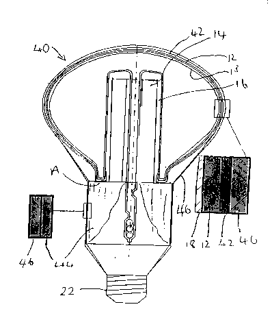
Figure 2 is a diagrammatic part-cut away cross-
section of an embodiment of the present invention.
Figure 1 has already been described.
Referring now to Figure 2, an embodiment 40 of the
present invention is shown with those parts in common
with the prior art lamp of Figure 1 being denoted by the
same reference numerals.
The glass discharge vessel 12 of the lamp has an
external coating of electrically conductive light
transmissive material, to provide EMI suppression.
The RF oscillator and rectifier (not shown) are
contained within, and supported by, a metal stamped
housing 44 which makes contact to the electrically
conductive layer 42 at annular region A preferably via a
thin conductive adhesive layer.
2S The vessel is supported directly or indirectly by
the housing 44. In Figure 2, the vessel 12 is supported
directly by the housing 44 at region A.
The vessel 12, with its outer conducting layer 42,
and the metal can 44 is covered by a one-piece
electrically insulating sleeve 46.
It may prove practicable to dispense with the
adhesive layer in region A in arrangements where the
sleeve 46 holds the components together sufficiently
tightly.
The sleeve 46 may be pre-formed and pulled over the
bulb and housing or may be formed by dipping. Suitable
materials are nylon and silicone but it is envisaged that

0 1 ~
- 4 - PQ-644
other suitable materials can be used.
The material should be selected according to the
proposed use of the lamp and manufacturing conditions,
for example ease of manufacture, high voltage breakdown,
good durability, heat resistance, clarity and long life
are some considerations. The sleeve may be coloured.
Silicone sleeves are already used for colouring and
waterproofing incandescent lamps and are available in a
variety of shapes and sizes.
The housing 44 can be made of a single-piece punched
metal can. This construction, compared to prior art
plastics housings provides not only cost advantages for
manufacture of the lamp but also provides improved
strength. The metal can be selectively strengthened in
specific regions by moulding rims and thickened areas
using well-known techniques of metal product manufacture.
A lamp cap 22 is fixed to the metal housing 44. If
the cap is a bayonet cap, a conventional bayonet cap may
be used or the cylindrical portion of cap may be formed
integrally with the housing 44 because the electrical
contacts are insulated therefrom. If an Edison-screw
cap is used, the screw threaded portion must be
electrically isolated from the metal housing 44 which
would otherwise be "live". The other contact of an
Edison-screw cap is isolated from the screw-threaded
portion.

Representative Drawing
A single figure which represents the drawing illustrating the invention.
Administrative Status

2024-08-01:As part of the Next Generation Patents (NGP) transition, the Canadian Patents Database (CPD) now contains a more detailed Event History, which replicates the Event Log of our new back-office solution.

Please note that "Inactive:" events refers to events no longer in use in our new back-office solution.

For a clearer understanding of the status of the application/patent presented on this page, the site Disclaimer , as well as the definitions for Patent , Event History , Maintenance Fee  and Payment History  should be consulted.

Event History

Description Date
Inactive: IPC from MCD 2006-03-12
Application Not Reinstated by Deadline 2003-10-17
Time Limit for Reversal Expired 2003-10-17
Deemed Abandoned - Failure to Respond to Maintenance Fee Notice 2002-10-17
Inactive: Status info is complete as of Log entry date 2001-10-31
Inactive: Application prosecuted on TS as of Log entry date 2001-10-31
Letter Sent 2001-10-31
Request for Examination Requirements Determined Compliant 2001-10-04
Amendment Received - Voluntary Amendment 2001-10-04
All Requirements for Examination Determined Compliant 2001-10-04
Application Published (Open to Public Inspection) 1997-04-19

Abandonment History

Abandonment Date Reason Reinstatement Date
2002-10-17

Maintenance Fee

The last payment was received on 2001-09-27

Note : If the full payment has not been received on or before the date indicated, a further fee may be required which may be one of the following

  • the reinstatement fee;
  • the late payment fee; or
  • additional fee to reverse deemed expiry.

Patent fees are adjusted on the 1st of January every year. The amounts above are the current amounts if received by December 31 of the current year.
Please refer to the CIPO Patent Fees web page to see all current fee amounts.

Fee History

Fee Type Anniversary Year Due Date Paid Date
MF (application, 2nd anniv.) - standard 02 1998-10-19 1998-09-16
MF (application, 3rd anniv.) - standard 03 1999-10-18 1999-09-24
MF (application, 4th anniv.) - standard 04 2000-10-17 2000-09-28
MF (application, 5th anniv.) - standard 05 2001-10-17 2001-09-27
Request for examination - standard 2001-10-04
Owners on Record

Note: Records showing the ownership history in alphabetical order.

Current Owners on Record
HANIF MAHOMED GIRACH
Past Owners on Record
None
Past Owners that do not appear in the "Owners on Record" listing will appear in other documentation within the application.
Documents

To view selected files, please enter reCAPTCHA code :


To view images, click a link in the Document Description column. To download the documents, select one or more checkboxes in the first column and then click the "Download Selected in PDF format (Zip Archive)" or the "Download Selected as Single PDF" button.

List of published and non-published patent-specific documents on the CPD .

If you have any difficulty accessing content, you can call the Client Service Centre at 1-866-997-1936 or send them an e-mail at CIPO Client Service Centre.


Document
Description 
Date
(yyyy-mm-dd) 
Number of pages   Size of Image (KB) 
Representative drawing 1997-08-14 1 25
Claims 2001-11-21 3 71
Abstract 1997-03-10 1 14
Description 1997-03-10 4 175
Claims 1997-03-10 1 32
Drawings 1997-03-10 1 40
Reminder of maintenance fee due 1998-06-17 1 111
Reminder - Request for Examination 2001-06-18 1 118
Acknowledgement of Request for Examination 2001-10-30 1 179
Courtesy - Abandonment Letter (Maintenance Fee) 2002-11-13 1 179