Sélection de la langue

Search

Sommaire du brevet 2188072 

Énoncé de désistement de responsabilité concernant l'information provenant de tiers

Une partie des informations de ce site Web a été fournie par des sources externes. Le gouvernement du Canada n'assume aucune responsabilité concernant la précision, l'actualité ou la fiabilité des informations fournies par les sources externes. Les utilisateurs qui désirent employer cette information devraient consulter directement la source des informations. Le contenu fourni par les sources externes n'est pas assujetti aux exigences sur les langues officielles, la protection des renseignements personnels et l'accessibilité.

Disponibilité de l'Abrégé et des Revendications

L'apparition de différences dans le texte et l'image des Revendications et de l'Abrégé dépend du moment auquel le document est publié. Les textes des Revendications et de l'Abrégé sont affichés :

  • lorsque la demande peut être examinée par le public;
  • lorsque le brevet est émis (délivrance).
(12) Demande de brevet: (11) CA 2188072
(54) Titre français: LAMPE FLUORESCENTE SANS ELECTRODE
(54) Titre anglais: ELECTRODELESS FLUORESCENT LAMP
Statut: Réputée abandonnée et au-delà du délai pour le rétablissement - en attente de la réponse à l’avis de communication rejetée
Données bibliographiques
(51) Classification internationale des brevets (CIB):
  • H01J 65/04 (2006.01)
  • H01J 61/35 (2006.01)
(72) Inventeurs :
  • GIRACH, HANIF MAHOMED (Royaume-Uni)
(73) Titulaires :
  • HANIF MAHOMED GIRACH
(71) Demandeurs :
  • HANIF MAHOMED GIRACH (Royaume-Uni)
(74) Agent: CRAIG WILSONWILSON, CRAIG
(74) Co-agent:
(45) Délivré:
(22) Date de dépôt: 1996-10-17
(41) Mise à la disponibilité du public: 1997-04-19
Requête d'examen: 2001-10-04
Licence disponible: S.O.
Cédé au domaine public: S.O.
(25) Langue des documents déposés: Anglais

Traité de coopération en matière de brevets (PCT): Non

(30) Données de priorité de la demande:
Numéro de la demande Pays / territoire Date
9521374.0 (Royaume-Uni) 1995-10-18

Abrégés

Abrégé anglais


An electrodeless fluorescent lamp includes a glass
envelope 12 at least of portion of the outer surface of
the glass envelope, being coated with an electrically
conductive layer 42, and a housing 44 made of metal which
makes electrical contact with the electrically
conductive layer 42, the bulb 12 and housing 44 being
covered at least partially by a one-piece insulating
sleeve 46.

Revendications

Note : Les revendications sont présentées dans la langue officielle dans laquelle elles ont été soumises.


- 5 -
CLAIMS
1. An electrodeless fluorescent lamp including a
discharge vessel the outer surface of the vessel being
coated with a light transmissive electrically conductive
layer, and a housing of metal which makes electrical
contact with the electrically conductive layer and which
supports the discharge vessel, the bulb and housing being
covered at least partially by a one-piece electrically
insulative layer.
2. A lamp as claimed in Claim 1 in which the
insulative layer comprises nylon, silicone or other
electrically insulative material.
3. A lamp as claimed in claim 1 or 2 in which the
insulative layer is coloured.
4. A lamp as claimed in claim 1, 2 or 3, in which
the vessel is fixed to the housing by electrically
conductive adhesive which makes an electrical connection
between the conductive layer and the housing.
5. A lamp as claimed in Claim 1, 2 or 3, wherein
the insulative layer holds the metal housing and the
discharge vessel together with the housing in electrical
contact with the conductive layer.
6. A lamp as claimed in any preceding claim,
wherein the insulative layer covers the whole of the
vessel and housing.
7. A lamp as substantially as hereinbefore
described with reference to Figure 2 of the accompanying
drawings.

Description

Note : Les descriptions sont présentées dans la langue officielle dans laquelle elles ont été soumises.

2 1 88072
- 1 - PQ-644
ELECTRODELESS FLUORESCENT LAMP
This invention relates to electrodeless fluorescent
lamps.
A typical prior art electrodeless fluorescent lamp
10 is illustrated at Figure 1. It has a discharge vessel
12 of glass containing an ionizable gaseous fill. A
suitable fill, for example, comprises a mixture of a rare
gas (e.g., krypton and/or argon) and mercury vapor and/or
cadmium vapor. An excitation coil 14 is situated within
a re-entrant cavity 16 within bulb 12.
The interior surfaces of the vessel 12 are coated in
well-known manner with a suitable phosphor 18. The
vessel 12 fits into one end of a base assembly 20
containing a radio frequency (RF) power supply (not
shown) with a standard (e.g., Edison type) lamp cap 22 at
the other end.
The RF power supply comprises a mains rectifier and
an RF oscillator (neither shown) which are contained in a
metal can 24 which is held at RF ground potential to
suppress RF radiation. The can 24 is insulated by a
rigid plastic housing 26. The plastic housing 26
surrounds the can and extends upwards to contact the
vessel 12. The housing supports the can and its
contents and the discharge vessel.
In operation, current flows in coil 14 as a result
of excitation by the RF power supply. As a result, a
radio frequency magnetic field is established within the
vessel 12 and which excites the gaseous fill contained
therein, resulting in an ultraviolet-producing discharge.
The phosphor 18 absorbs the ultraviolet radiation and
consequently emits visible radiation.
There are several disadvantages associated with such
prior art lamps. The vessel 12 has an internal coating
of light transmissive electrically conductive material to
confine the RF within the vessel. A conductive layer is
provided on the outer surface of the vessel capacitively

2 1 8~072
- 2 - PQ-644
coupled with the internal conductive coating. The outer
layer is connected to RF ground via an electrical
connection such as a foil. The connection is difficult
to make. In addition, the can and housing constitute a
s significant cost of the lamp.
The present invention seeks to provide an improved
discharge lamp. It comprises an electrodeless
fluorescent lamp including a discharge vessel, at least
of portion of the outer surface of the vessel being
coated with light transmissive electrically conductive
layer and a housing of metal which makes electrical
contact with th~ electrically conductive layer and which
supports the discharge vessel and energising circuits of
the lamp, and the vessel and housing being covered at
least partially by a one-piece insulative layer.
The metal housing of the present invention is
readily manufactured by using well established metal
punching techniques, obviating the need for a foil
connection due to the direct contact of the metal housing
and the electrically conductive layer surrounding the
glas~ envelope as well as providing a good heat sinking
ability. The direct connection may be made by a
con~uctive adhesive or by contact of the cap with the
electrically conductive layer.
The insulative layer functions to make the lamp
electrically safe and may also fix or help to fix the
discharge vessel to the metal housing. The layer does
not support the housing and/or the discharge vessel.
The one-piece au~Lou..ding insulative layer provides
a high degree of waterproofing and good insulation.
Little or no adhesive is required to hold the di~ch~rge
vessel to the housing. By making the lamp shatterproof
the insulative layer extends the areas in which such
discharge lamps can be employed into, for example, the
food industry.
The use of a conductive layer over the bulb's outer
layer means the EM suppression is not dependant on the

2 t ~f~0~2
_ 3 _ PQ-644
thickness of the glass envelope so allowing a reduction
in manufacturing tolerances as regards thickness
distribution of the glass envelope.
An embodiment of the invention will now be
described, by way of example only, with reference to the
accompanying drawings, of which :
Figure 1 is a diagrammatic part cut-away cross-
section of a prior art electrodeless fluorescent
discharge lamp; and
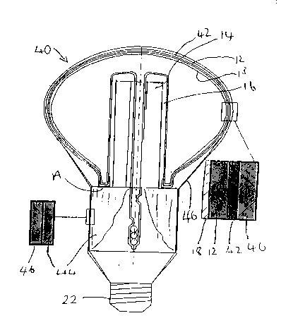
Figure 2 is a diagrammatic part-cut away cross-
section of an embodiment of the present invention.
Figure 1 has already been described.
Referring now to Figure 2, an embodiment 40 of the
present invention is shown with those parts in common
with the prior art lamp of Figure 1 being denoted by the
same reference numerals.
The glass discharge vessel 12 of the lamp has an
external coating of electrically conductive light
transmissive material, to provide EMI suppression.
The RF oscillator and rectifier (not shown) are
contained within, and supported by, a metal stamped
housing 44 which makes contact to the electrically
conductive layer 42 at annular region A preferably via a
thin conductive adhesive layer.
2S The vessel is supported directly or indirectly by
the housing 44. In Figure 2, the vessel 12 is supported
directly by the housing 44 at region A.
The vessel 12, with its outer conducting layer 42,
and the metal can 44 is covered by a one-piece
electrically insulating sleeve 46.
It may prove practicable to dispense with the
adhesive layer in region A in arrangements where the
sleeve 46 holds the components together sufficiently
tightly.
The sleeve 46 may be pre-formed and pulled over the
bulb and housing or may be formed by dipping. Suitable
materials are nylon and silicone but it is envisaged that

0 1 ~
- 4 - PQ-644
other suitable materials can be used.
The material should be selected according to the
proposed use of the lamp and manufacturing conditions,
for example ease of manufacture, high voltage breakdown,
good durability, heat resistance, clarity and long life
are some considerations. The sleeve may be coloured.
Silicone sleeves are already used for colouring and
waterproofing incandescent lamps and are available in a
variety of shapes and sizes.
The housing 44 can be made of a single-piece punched
metal can. This construction, compared to prior art
plastics housings provides not only cost advantages for
manufacture of the lamp but also provides improved
strength. The metal can be selectively strengthened in
specific regions by moulding rims and thickened areas
using well-known techniques of metal product manufacture.
A lamp cap 22 is fixed to the metal housing 44. If
the cap is a bayonet cap, a conventional bayonet cap may
be used or the cylindrical portion of cap may be formed
integrally with the housing 44 because the electrical
contacts are insulated therefrom. If an Edison-screw
cap is used, the screw threaded portion must be
electrically isolated from the metal housing 44 which
would otherwise be "live". The other contact of an
Edison-screw cap is isolated from the screw-threaded
portion.

Dessin représentatif
Une figure unique qui représente un dessin illustrant l'invention.
États administratifs

2024-08-01 : Dans le cadre de la transition vers les Brevets de nouvelle génération (BNG), la base de données sur les brevets canadiens (BDBC) contient désormais un Historique d'événement plus détaillé, qui reproduit le Journal des événements de notre nouvelle solution interne.

Veuillez noter que les événements débutant par « Inactive : » se réfèrent à des événements qui ne sont plus utilisés dans notre nouvelle solution interne.

Pour une meilleure compréhension de l'état de la demande ou brevet qui figure sur cette page, la rubrique Mise en garde , et les descriptions de Brevet , Historique d'événement , Taxes périodiques et Historique des paiements devraient être consultées.

Historique d'événement

Description Date
Inactive : CIB de MCD 2006-03-12
Demande non rétablie avant l'échéance 2003-10-17
Le délai pour l'annulation est expiré 2003-10-17
Réputée abandonnée - omission de répondre à un avis sur les taxes pour le maintien en état 2002-10-17
Inactive : Renseign. sur l'état - Complets dès date d'ent. journ. 2001-10-31
Inactive : Dem. traitée sur TS dès date d'ent. journal 2001-10-31
Lettre envoyée 2001-10-31
Exigences pour une requête d'examen - jugée conforme 2001-10-04
Modification reçue - modification volontaire 2001-10-04
Toutes les exigences pour l'examen - jugée conforme 2001-10-04
Demande publiée (accessible au public) 1997-04-19

Historique d'abandonnement

Date d'abandonnement Raison Date de rétablissement
2002-10-17

Taxes périodiques

Le dernier paiement a été reçu le 2001-09-27

Avis : Si le paiement en totalité n'a pas été reçu au plus tard à la date indiquée, une taxe supplémentaire peut être imposée, soit une des taxes suivantes :

  • taxe de rétablissement ;
  • taxe pour paiement en souffrance ; ou
  • taxe additionnelle pour le renversement d'une péremption réputée.

Les taxes sur les brevets sont ajustées au 1er janvier de chaque année. Les montants ci-dessus sont les montants actuels s'ils sont reçus au plus tard le 31 décembre de l'année en cours.
Veuillez vous référer à la page web des taxes sur les brevets de l'OPIC pour voir tous les montants actuels des taxes.

Historique des taxes

Type de taxes Anniversaire Échéance Date payée
TM (demande, 2e anniv.) - générale 02 1998-10-19 1998-09-16
TM (demande, 3e anniv.) - générale 03 1999-10-18 1999-09-24
TM (demande, 4e anniv.) - générale 04 2000-10-17 2000-09-28
TM (demande, 5e anniv.) - générale 05 2001-10-17 2001-09-27
Requête d'examen - générale 2001-10-04
Titulaires au dossier

Les titulaires actuels et antérieures au dossier sont affichés en ordre alphabétique.

Titulaires actuels au dossier
HANIF MAHOMED GIRACH
Titulaires antérieures au dossier
S.O.
Les propriétaires antérieurs qui ne figurent pas dans la liste des « Propriétaires au dossier » apparaîtront dans d'autres documents au dossier.
Documents

Pour visionner les fichiers sélectionnés, entrer le code reCAPTCHA :


Pour visualiser une image, cliquer sur un lien dans la colonne description du document. Pour télécharger l'image (les images), cliquer l'une ou plusieurs cases à cocher dans la première colonne et ensuite cliquer sur le bouton "Télécharger sélection en format PDF (archive Zip)" ou le bouton "Télécharger sélection (en un fichier PDF fusionné)".

Liste des documents de brevet publiés et non publiés sur la BDBC .

Si vous avez des difficultés à accéder au contenu, veuillez communiquer avec le Centre de services à la clientèle au 1-866-997-1936, ou envoyer un courriel au Centre de service à la clientèle de l'OPIC.


Description du
Document 
Date
(aaaa-mm-jj) 
Nombre de pages   Taille de l'image (Ko) 
Dessin représentatif 1997-08-14 1 25
Revendications 2001-11-21 3 71
Abrégé 1997-03-10 1 14
Description 1997-03-10 4 175
Revendications 1997-03-10 1 32
Dessins 1997-03-10 1 40
Rappel de taxe de maintien due 1998-06-17 1 111
Rappel - requête d'examen 2001-06-18 1 118
Accusé de réception de la requête d'examen 2001-10-30 1 179
Courtoisie - Lettre d'abandon (taxe de maintien en état) 2002-11-13 1 179