Note: Descriptions are shown in the official language in which they were submitted.
2188074
DOCKET NO. 1955/OC427
PROCESS FOR CONVERTING AND PRINTING ON WEBS,
AND A PRINTING MACHINE FOR CARRYING OUT THIS PROCESS
BACKGROUND OF THE INVENTION
1. Field of the Invention
The present invention relates to a process for converting and printing on
paper
webs, and to a printing machine for printing on converted webs to carry out
this process.
2. Discussion of the Related Art
Frequently, the base paper that exits a paper machine requires an additional
conversion to account for the different requirements so that the paper can be
printed on. The
principle conversion processes are coating and calendering.
In coating, a coating dye that consists of pigments and fixing agents is
applied,
with the aid of a coating machine, to the base paper on one or both sides of
the paper.
Coating a base paper produces a closed and smooth, easily printable paper
surface.
In calendering, smoothness and/or gloss are created, with the aid of a
calender,
on the surface of the base paper. Calendering a base paper increases the
ability to apply ink
during the printing process. Calenders typically have at least one roller gap,
and preferably
have several roller gaps. The roller gaps are defined by the juncture of a
hard and soft
roller. The hard rollers are preferably heatable rollers that are made of
chill casting or steel.
The soft rollers are preferably provided with a flexible outer covering. The
web (e.g., the
base paper) is subjected to a pressure treatment and, in most cases, a
temperature treatment
in these roll gaps, which create the desired smoothing of the web. Such
calenders are
generally well known. An example of such a calender is disclosed, for example,
in German
Reference DE-U-295 04 034.3.
_._~~.e....._. . _ ~.~~.___..
2188074
2
Coating machines and calenders have conventionally been set up in paper
factories and have been placed behind (i.e., downstream) with respect to a
paper machine in
the work sequence, either in-line or off line. The converted web, which has a
width
corresponding to the paper machine, is formed into a roll in a wind-up device.
During the
winding-up process, there is a great deal of difficulty in creating a
uniformly wound roll,
particularly due to the fact that the web, because of its great surface
smoothness, tends to slip
sideways on a cushion of air that is present during the winding-up process.
To further process the web of paper in a printing plant, the rolls are usually
cut,
while still in the paper factory, into narrower rolls that match the width of
the printing
machines. The cutting of the roll is typically done by a roll-slitting
machine, which divides
the wide web that is unwound from a roll into separate partial webs by means
of longitudinal
cutters. Each of these separate partial webs are wound into a separate roll of
lesser width in a
winding station. With this second winding-up process there is still a tendency
for the webs to
slip sideways because of their relatively smooth surfaces.
The individual rolls that are made from the converted webs of paper must
subsequently be individually packaged so that they can be transported to a
printing plant in a
protected manner. Additionally by packaging the individual rolls, the paper's
moisture can be
retained. Of course, this packaging of each individual roll is quite
expensive.
Accordingly, it is an object of the present invention to improve the
preparation
of converted paper for printing.
SUMMARY OF THE INVENTION
This object is achieved in accordance with the present invention by converting
the running web and subsequently printing thereon with no intermediate winding-
up process.
In accordance with one aspect of the present invention there is provided a
process of converting and printing on paper webs comprising the steps of:
converting an
unconverted running web of a base paper with a calender that includes a roller
stack
comprised of at least one hard roller and at least one soft roller, a roller
gap being formed at
the juncture of one of said hard rollers and one of said soft rollers;
printing on the converted
21~8U74
2a
web with no intermediate winding-up process; and wherein the web is cut before
the
convertW g step so that the web is cut to the width required for printing.
In accordance with another aspect of the present invention there is provided
an
apparatus for printing on converted paper webs comprising: a calender for
converting an
unconverted web of base paper, said calender including a roller stack
comprised of at least
one hard roller and at least one soft roller, a roller gap being formed at the
juncture of one of
said hard rollers and one of said soft rollers; and a printing machine having
an entrance for
receiving the converted web from said calender; wherein the pass-through speed
of the web
through said calender matches the pass-through speed of the converted web
through said
printing machine.
Thus, the method according to the present invention dispenses with the
requirement of winding the converted paper into a roll. Shortly after the
completion of the
conversion treatment, the running web enters into the printing area. The
individual rolling-up
process in the paper factory is, thus, made substantially simpler because only
the base paper
has to be formed into a roll (i.e., wound-up). Because of the relatively rough
surface and
2 ~ ~~0~4
3
the greater volume of the base paper, it can be wound significantly more
easily than paper
that has been converted and is, therefore, smooth.
A further advantage of the present invention is the improved printing quality
that can be achieved. Conventionally, it is practically impossible to avoid
losing smoothness
in the converted web of material during the long periods of storage and
transport before the
web was printed on in the printing process. This loss of smoothness can be
attributed to the
fact that the fibers, which have been leveled on the surface of the web, relax
and stand up
again over time. In accordance with the present invention, however, only a
very short period
of time exists between the conversion and the printing of the web. Thus, it is
practically
impossible for the surface fibers to stand up again during this relatively
very short period of
time. Thus, it is also possible to adjust or regulate the surface smoothness
of the base paper
so that it is optimally matched to the application of ink during printing.
The yet unconverted web is preferably cut to the width required for printing,
formed into a roll, and drawn off this roll for conversion and printing. Thus,
a wide web is
cut into several partial webs in the paper factory as usual, but these partial
webs have yet to
be converted. Thus, the partial webs can be wound up easily. In addition, less
expensive
packaging can be used because the web has not yet reached its final conversion
stage, and
because the moisture content can still be used during the coating or
calendering processing.
The converted web is optionally tempered before the printing step to achieve
an especially good adapting of the web to the printing process.
The conversion can be achieved by calendering or coating, or through coating
and subsequent calendering. The entire conversion is preferably carried out in
the printing
plant. But substantial advantages of the present invention can still be
achieved even if only
the concluding conversion treatment is carried out together with the printing
during a single
pass (in other words, a portion of the conversion has already been carried out
in the paper
factory).
In accordance with the present invention, a facility for the conversion of the
web of paper is disposed in front of the entrance to the printing machine. The
pass-through
speed of the conversion facility matches that of the printing machine.
. __..._ ___w..~w.~ _..~.. . ______.._~...~-
..~.~..~..~...~~.___~..~._.~_.____. w .. ~ . . .___~.____~__... _
4
The conversion facility can be a coating device and/or a satirizing calender.
In both cases, the surface of the web of paper is smoothed, which improves the
printing
process.
Because the pass-through speed of the conversion facility matches the pass-
through speed of the printing machine, the conversion facility works
comparatively slowly.
In the case of a coating machine, the coating dye can be carefully applied
with little effort.
In the case of a calender, longer hold or dwell times of the web in the roller
gap result,
which leads to higher smoothness values. In addition, a calender that runs
slower than
calenders that are commonly used in paper factories is easier to manufacture
and operate, and
is less expensive to produce and operate.
The working width of the conversion facility is equal to or slightly greater
than
(i.e., is approximately equal to) that of the printing machine. Because the
conversion facility
can be allocated to a specific printing machine, the working width of the
conversion facility
can be matched to that of the printing machine. Thus, the conversion facility
has a lesser
width in comparison with the coating machines and calenders that have been
commonly used
in paper factories. Because of the smaller width, in combination with the
slower speed, the
conversion facility according to the present invention has markedly lower
production costs.
In a further embodiment, a tempering facility, which affects the web
temperature, is disposed between the exit of the conversion facility and the
entrance to the
printing machine.
BRIEF DESCRIPTION OF THE DRAWING FIGURES
The above and still further objects, features and advantages of the present
invention will become apparent upon consideration of the following detailed
description of
a specific embodiment thereof, especially when taken in conjunction with the
accompanying
drawings wherein like reference numerals in the various figures are utilized
to designate like
components, and wherein:
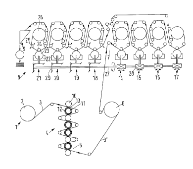
Fig. 1 is a schematic illustration of a combination calender and printing
machine;
_. ..._ ._ ~._~.__~_.~...__
2188074
s
Fig. 2 is a schematic illustration of a combination coating machine and
printing
machine; and
Fig. 3 is a logic diagram showing the process sequence.
DETAILED DESCRIPTION OF THE PREFERRED EMBODIMENT
Referring now to Fig. 1, a winding off station 1 is illustrated. Wind-off
station
1 includes a roll 2, which contains a web 3 of uncalendered (i.e.,
unconverted) paper. Web
3 runs through a calender 4. Web 3 leaves an exit 5 of the calender as a
calendered web
(i.e., a converted web 3'). Converted web 3' then winds, by an angle of more
than 180°,
around a tempering roller 6, which determines the web temperature. Thereafter,
converted
web 3' enters into an entrance 7 of a printing machine 8. Thereafter,
converted web 3'
enters into a folding apparatus 9, which is disposed at the end of the
printing machine 8.
Calender 4 is comprised of hard rollers 10 and soft rollers 11. Hard rollers
10 are made of steel or chilled casting and are heated. Soft rollers 11 have a
flexible outer
covering 12. The rollers 10 and 11 are pressed in their working directions
against each other
by a device (not shown) so that the web 3 is affected by pressure and
temperature in the
roller gaps 13, and is smoothed as a result.
Printing machine 8 has four printing couples 14-17 for the first printing and
four printing couples 18-21 for the second printing. Thus, printing machine 8
is an eight-
color gravure, web-fed rotary press. The individual printing couples 14-21
each have
engraved cylinders 23, which dip into ink troughs 22, in a conventional
manner. In each
printing couple, web 3' is guided between engraved cylinder 23 and an adjacent
rubber
impression cylinder 24, and, with the aid of tensioning means 25, is
subsequently directed
over at least one drying cylinder 26. Printing machine 8 has a common drive
shaft 27, which
drives the engraved cylinders 23 by means of appropriate transmissions 28 or
29.
A matching of the smoothness or gloss values to the requirements that have
to be met for optimum printing in the printing machine 8 can be attained by
regulating the
pressure in the roll gap and/or the temperature of the hard rollers 10.
z ~ ~00~4
6
Referring now to Fig. 2, a coating machine 30 is illustrated.. A winding-off
station 31 is disposed upstream of (or in front ofj coating machine 30 as
viewed from the
direction of movement of web 32. A printing machine 8 is disposed downstream
from
coating machine 30. Printing machine 8 corresponds to the printing machine 8
illustrated in
Fig. l, and terminates with a folding apparatus 9. Web 32 is unwound from
winding off
station 31 and enters into coating machine 30. Web 32 runs through a path,
which is defined
by guide rollers 33. Coating dyes are applied at a coating basin 34, and the
excess is stripped
off by means of a wiping blade 35. Subsequently, a first drying step is
carried out in an
infrared heating facility 36, and a second drying step is carried out in a hot-
air drying facility
37. The now coated web 32' (i.e., a converted web 32') next winds partly
around heating
roller 6, and then enters printing machine 8. The web of paper is, thus, taken
from a stored
roll in an unwinding station 31, directed through a converting facility,
namely, coating
machine 30, and is then guided directly into printing machine 8.
Referring now to Fig. 3a, a logic diagram is illustrated. A roll cutting and
winding facility 39 is disposed at the exit of a paper machine 38. The web of
base paper,
which has the same width as the paper machine, is cut into narrower webs in
the roll cutting
and winding facility. The cut narrower webs are then wound into individual
rolls. These
rolls, which have a lesser width than the base paper, are packaged in a
packaging station 40.
A dashed line 41 schematically represents the border between a paper factory
42 and a
printing plant 43, which can be at any distance from one another. In the
printing plant 43,
the web is unwound in an unwinding station 31, directed through a coating
machine 30 and
a calender 4, and is directed to a printing machine 8, without any kind of
intermediate
winding. In this case, web 32 undergoes the effects of a coating machine 30,
and then
directly undergoes the effects of a calender 4.
Printing machines other than the illustrated eight-color gravure, web-fed
rotary
press can be used. For example, printing machines that work by means of high-
pressure or
planographic printing can be used. Additionally, calenders other than the
illustrated seven
roller gap calender 4 can be used. For example, a calender having a stack that
is comprised
of a greater number of rollers, or a calender with a smaller number of rollers
can be used.
218074
Thus, for example, a soft calender that has one roller gap or two roller gaps
connected one
after the other could be used without departing from the spirit of the present
invention.
Having described the presently preferred exemplary embodiment of a process
for converting and printing on webs, and a printing machine for carrying out
this process in
S accordance with the present invention, it is believed that other
modifications, variations and
changes will be suggested to those skilled in the art in view of the teachings
set forth herein.
It is, therefore, to be understood that all such modifications, variations,
and changes are
believed to fall within the scope of the present invention as defined by the
appended claims.