Note: Descriptions are shown in the official language in which they were submitted.
21 881 73
1 PORTABLE CRUSHER FOR cONCRETE
z BACKGROUND OF ~HE 1N Y~.~ ON
3 1. ~ield of the Invention
4 This invention relates generally to the field-o~
concrete crushing, rock cr~lch~, mining, and recycling of
6 concrete and other mate~ials, and speci~ically to a
concrete crushing plant transportable over highway system6
8 to construction and demolition sites.
9 2. Description of the Related Art
Portable crll~h;~ plants ~or rock, concrete and other
11 demolition materials have been developed for appli~ations
12 where the quantity of material to be crushed at a
13 particular site is limited. Highway portability i
~4 important, ~or example, in non-min;n~ applications such as
in building demolition or in clearing the wreckage
16 ~ollowing a natural disaster, such as an earthquake.
17 However, high capacity machinery in a typical plant, rated
18 in ton~ per hour, can o~ten exceed the legal weigh~ li~its
19 specified by the federal or state government for i~s
roadways. ThiS situation has been overcome, in pa~t, ~y
21 br~;n~ down the plant into s~ co:-p~nents that ar~,
22 separately transported to a new site and then reas~embled.
23 Typical~y, where the crusher i~ fed with a vibrato~y
~4 hopperlfeeder, it has been a cu6tom in large capacity
Z5 plants to transport the vibratory hopper/feeder se~.7arately
26 on a general uti~ity trailer. At a new ~ite, a he~vy crane
27 is used to lift the hopper/feeder from the transpoxt
28 trailer onto ~he framework o~ the main part of the plant.
29 When a job is completed, this ~et-up process i~ reversed
again using a heavy crane to lift the hoppert~eeder from
31 the main structure to a utility trailer~ ~his set-up
2188173
,
1 pr~ re, although co~monly used, ~ very costly because
2 o~ crane rental charges incurred at the beg;~nin~ and end
3 of a job. When a plant i~ only at a location for a short
4 period of time, the crane rental cha~ge~ can greatly
increase the overall co~t Or the ~ ob.
6 Various crushing apparatus a~e shown in U.S. Patent~
7 No~. 4,383,651 to ro~rruS, 4,585,179 to Tsuji, 4,598,875
8 to Bronson, 4,655,402 to Desourdy, 4, 881,691 to Oldengott,
9 4,951,885 to Th~s, 5,026,205 to Gorski, and 5,161,~44 to
Schoop, all incorporated herein by reference.
11 SUMMARY OF TH13 INVENTION
12 The pre~ent invention provide~ a portable c~h;n~
13 plant that o~ers a large production capacity and avoids
14 co~tly and co~plicated set-up and take-down proc~ res,
such a~ the u~e of a heavy crane to install the plant
-16 equlpment.
17 In particular, the porta~le crushing plant include~ a
18 crusher ~i~pQc~ on a fi~t movable vehicle; a classi~ier
l9 di~posed on a second movable vehicle and adapted for
classifying material according to size; a feed con~eyor for
21 car~ying output material from the cr~sher to the
z2 classifier; and a return conveyor for returning oversize
23 material from the classifier to the crusher.
24 The trailers are supported on ground engaging ~h~
The cru~her iæ di~po6ed on the ~irst trailer and has a side
26 chute ~or receiving material. A plu~ality of jacks are
Z7 adapted for elevating the first trailer. A swingable under
28 crusher conveyor is dispQ~ed on the flrst trailer ~nd under
29 the crusher for conveying o~tput material ~rom the,cru~her.
The first feed conveyor extends ~rom beneath the c~usher
31 and is adapted ~or conveying material ~rom the und~r
32 cru~her conveyor. The conveyor extends laterally from the
33 trailer and is retractable. A hopper is supported on
34 ground engaging leg~ and i~ adapted for being po6itioned
- 2188173
....
1 over the first trailer ~o as to rest thereon when the first
2 trailer is elevated. ~he hopper is adapted for classifying
3 material received therein and dischar~es undersize ~aterial
4 on the ~eed conveyor and discharges oversize material to
the crusher.
6 The ~on~ movable trailer is adapted for being
7 positioned adjacent the first trailer so as to extend
8 laterally therefrom. A plurality o~ ~acks are adapte~ ~or
g elevating a forward end of the second trailer. A second
10 f eed conveyor is adapted for communicating with th~ fir3t
11 feed conveyor. A funnel directs mater~al from ~h~-~irst
12 feed conveyor to the second feed conveyor. A magnet~c
13 ~eparator is di~o~cd ad~ace~t th2 second f eed conveyor and
14 adapted ~or remo~ing magnetic material f~om the second ~eed
conveyor. ~he separator is pivotably mounted for ~ovement
16 between travel and operating positions. A vibrata~le
17 screen as6embly is adapted for receiving ~aterial from the
18 ~econ~ feed conveyor a~d has screens adapted for
19 clas~ifylng the material according to size. A ~;-C~rge
conveyor is ~i~ r~ belo~ the screen assembly and adapted
21 for con~eying output material p~sce~ ~y ~he screen
2 2 ~ ~.c~hl y. Lateral conveyors are dispo~ed at return end~ of
23 the ~creens and adapted for receiving oversize matQrial
Z4 therefrom. A return conveyor is adapted for recei~ing
material from the lateral conveyor~ and conveying the
26 material to the side chute of the crusher. The return
27 conveyor is pivotably mo~nted to the second traile~. A
28 retractable cable is disposed between the econd trailer
29 and the return conveyor and adapted for pivoting the second
feed conveyor between a travel position and an operating
31 position. A shroud is disposed adjacent the lateral
32 conveyors and mounted for movement with an end of the
33 return conveyor to partially enclose the lateral conveyors.
2183173
1 B~T~F D~SCRIPTION OF ~HE D~AWINGS
2 Fig. 1 ~hows a side ele~ation o~ a ~irst trailer
3 equipped with a crus~er and conveyors in a retracted state
~ according to ~he invent~on;
Fig. Z shoWs a side elevation o~ a hopper according to
6 the invention;
7 Fig. 3 ~hows a side elevation of a second trailer
8 e~uipped with a screen and conveyorfi in a retracted ~tate
9 according to the inven~ion;
Fig. 4 shows a side elevation of the fir~t trailer in
11 an operative ~tate with th~ hopper installed thereon;
12 Fig. 5 ~how~ a rear end elevation of the first trailer
13 shown in Fig. 4;
14 Fig. 6 shows a side elevation of the s~cond trailer in
an operative ~tate; and
16 ~ig. 7 shows a top plan view of the trailers ~-ss~hled
17 to ~orm a cr~ ch in~ and screening plant according to the
18 invention.
l9 DESC~lP~lON OF THE ~ ~n EMBODIMENT
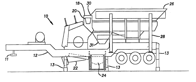
Re~erring to ~ig. l, components of a crushing plant 10
21 are mount~d on a first movable trailer 12. Preferably, the
2Z trailer 12 i~ provided with g~ou~d eng~ging wheels~and is
23 adapted for being pulled ~y a tractOr over streets and
24 highways. A modified flatbed trailer with a pin ll for
connecting to a tractor is sUitable. Jacks 13 or
26 extendable legs are p~ovided for elevating the trailer 12
27 to a stable operative po5ition with the wheels of* the
28 groun~, a6 shown in Fig. ~- In the operative position the
29 trailer load is substantially removed from the whe~l~. A
crusher 14 is pro~ided abo~t ~idw~ ~long the length of the
31 ~railer 12. suitable crushers aro w~ll known ln t~e art
32 and include an electric motor or co~bu~tion enginejl6 that
33 power~ a rotating member (not shown) The rotatin~ -.~ h~r
2l 8~l 73
l is adapted for disintegrating material, s~ch a~ concrete,
2 into smaller chunk~. The cru~her 14 is provided with an
3 inlet 18 adapted ~or receiving the ~aterial to ~e Grushed.
4 The inlet 18 is also provided with a side chute 20 adapted
for receiving material from a side o~ ~he crushe~ 14 and
6 directing the material into the inlet 18, as ~ A~
7 ~Qlow.
8 The firet trailer 12 i5 al60 provided with an under
9 crusher conveyor 22 adapted ~or ~liding or pivoting between
a retracted position, shown in Fig. l, and an operative
ll pOSition, shown in Fig. 4. In the retracted po~ition, the
12 under cru~her conveyor 22 provides adequate clearance ~rom
13 the grOund to permit travel of the trailer lZ. A ~ir6t
14 fe~d conveyor 24 or auxiliary ~eed conveyor is di~po~ed on
a side of the first ~railer 12. A relatively hori20ntal
16 part 24a o~ the feed conveyor 24 extends ~nder the trailer
17 near the crusher 14. The ~eed conveyor 24 is mounte~ ~or
18 vertical movement on the trailer between a retracted
19 pO~ition, ~hown in Fig. 1, and an operative positi~n, ~hown
in Fig. 4. In the retracted po~ition, the feed con~eyor 24
21 provideS adequate clearance from the ground to per~it
22 t~avel of the trailer 12. An inclined part 24b o~ the
23 first feed conveyor 24 extends upwardly from the h~rizontal
24 part 24a past a ~ide of the trailer 12. ~he inclin~d part
~5 24b i~ pivotably mounted at the horizontal part ~or
26 movement between a retracted position, ~hown in Fig~ l, and
27 a sloped, operative position, shown in Figs. 4 and ~. The
28 conveyors 22, 24 de~cribed above and others described below
29 are generally conventional in construction, each haYing an
endless belt suitable for transporting crushed ma~rial
31 from one location to another.
32 Referring to Figs. 2 and 7, a vibratory hopper 26 is
33 ~upported on fo~r extendable legs 28 or jacks. ~h6 hopper
34 is adapted for recei~ing material ~rom a front end loader,
~or example, and provided with a screen 29 or "gri~zly
36 deck~ adapted for classifying material by size. The hopper
2188173
1 26 i~ si2ed so as to be portable on a semi-trailer and the
2 leg~ 28 are spaced so as to be capable o~ ~traddling the
3 ~irst trailer 12, as shown in Figs. 4 and 5. The hopper 26
4 is provided with an outlet end 30 adapted for communicating
with the inlet 18 of the crusher 14 so as to direct
6 oversize ~aterial ~rom the hopper into t~e cru~her.
7 Under6i~e material that does not reguire cr~l~h;~ is r~
8 by the screen 29 and falls through discharge port 31.
9 Re~erring to Fig. 3, a scr~en~n~ plant 32 is d~po~ed
on a ~on~ trailer 34. Preferably, the second trailer 34
11 is provided with g~ound engaging wheels ~nd a pin 35 and is
12 adapted for be~ ng pulled by a tractor over streets and
13 highway6. A modified flatbed trailer is suitable. Jacks
14 36 or ex~en~hle ~ egs are provided ~or elevating the
trailer ~4 to a stable operative po~ition, a~ 6hown in Fig.
16 6. A screen assembly 38 is pro~ided a~out midway along the
17 length of the second trailer 34. Suitable screen
18 assemblies are well known in the art and typically co~prise
19 a vibratory enclosure supporting one or more screens 39 or
~'grizzly decks" adapted for passing material smaller than a
21 certain size and directing larger, oversize material to a
22 return end 40 of the enclo~ure.
23 A second feed conveyor 42 is provided on the ~econd
24 ~railer 34 and terminates over an input end of the screen
~e~hly 38. A funnel 44 disposed at an end o~ the second
26 ~eed conveyor 42 is adapted for receiving material f~om the
27 first feed conveyor 24 and directing it to the ~sn~ feed
28 conveyor 42. A ~;~r~rge conveyor 46 i~ disposed below the
29 screen as~embly 38 for collecting and transporting the
material pas~ed ~y the screens. One or more lateral
31 ~onveyor~ 48 are located across the return end 40 of the
32 ~creen ~c~ hly 38. These a~e located so as to receive and
33 convey material not passed or partially passed by the
34 ~creen a~sembly 38. A shroud 49 is di~po~ed around the
lateral conveyor~ 48 to prevent 6pillage. A return
36 conveyor 50 is located at an end of the lateral conveyors
2188173
l 48 and adapted to receive material therefrom. The return
2 conveyor 50 extend~ rearwardly along a side of the second
3 trailer 34. An end of t~e return conveyor S0 is movably
4 SU~G~ ~ed by a retractable cable 52 extending from a
s~n~n 54 mounted on the trailer 34. The cable S2 i~
6 ret~actable by a winch 56, ~or exa~ple. A magnetic
7 separator 56 is pivotably ~ounted at a front end of the
8 ~econd trailer 34 and adapted to be positioned over an end
9 of the ~on~ feed conveyor 42 over the screen ~c~r~ ~ly 38.
~rection and operation o~ the c~lchin~ plant lO and
11 ~cr~n;~ plant 32 can best be under~tood by rs~erence to
12 Figs. 4 through 7. As shown in Fig. 4, the first trailer
13 12 ia h~ c~e~ under the hopper 26, which i8 ~upported on the
14 ground at a location where the crushing is to occur. The
trailer 12 i~ posit~one~ ~o that the hopper outlet end 30
16 is disposed above the crusher ~nlet 18 and the ~;e^h~rge
17 port 29 is over the first feed conveyor 24. ~he ~ir~t
18 ~railer 12 is elevated on the j acX~ 13 to support the
ls hopper 26 on the trailer. ~he first feed conveyor 24 is
lowered and the under crusher conveyor 22 i~ moved beneath
21 the cru~her 14 so that an end of the under crusher conveyor
22 is ocated above the horizontal part 24a o~ the ~irst feed
23 conveyor.
24 A~ shown in Fig. 7, the second t~ailer 34 is moved
adjacent the first trailer lZ so that longit~ l axe~ of
Z6 the trailers lZ, 34 intersect at about a 70~ angle. The
27 end of the return conveyor 50 is positioned over the ~i~e
28 chute 20 o~ the cru~her 14. As shown in Fig. 6, the ~ront
29 end of the second trailer 34 is pivoted upwar~ly and
supported by t~e jacks 36 while the cable 52 is retracted
31 to pivot the return conveyor 50 upwardly. Thu~, the ~econd
32 feed 40 and return 50 conveyor~ have non-intersecting
33 longitudinal axe6 generally ~orming an ~'X. ~I The &hroud 49
34 mo~es with the ~eturn conveyor 50 to partially enclo~e the
lateral conveyors 43. Pivoting the front end of t~e
36 trailer 34 upwardly lower~ th8 end of the second feed
2138173
.
1 conveyor 42 and the funnel 44 at the rear o~ the t~ailer.
2 A~ ~hown in Fig. 5, the inclined part 24b of the ~ir~t ~eed
3 c~nveyor 24 is pivoted downwardly from the generally
4 ~e~tical transport position so that the inclined part
remains in an upwardly sloping position. The ;~cl; n9~ part
6 24b terminate~ over the funnel 44. Referring to Fig. 6,
7 the magnetic separator is pi~oted over the end ~ the
8 secona feed conveyor 42.
9 The flow of operation is apparent from the as~embly as
shown in Fig. 7. Raw material to be crushed is loa~ed into
11 the hopper 26 fro~ where oversize material moves by
lZ vibration and gravity to the crusher 14 ~rom the hopper
13 outlet end 30 into the crusher inlet 18. The crusher 14
14 crushes the over~ize material, which is discharged onto the
under c~usher conveyor 2Z tFig. 4). ~he material move~ on
16 the under crusher conveyor 22 to the first feed conveyor
17 24, whlch ~erves a~ an auxiliary ~eed conveyor ~or moving
18 material to the 6econd or main feed conveyor 40. Ullder~ize
19 material that does not require crll-C~; n~ is passed by the
screen 29 and falls through the hopper discharge port 31
21 directly to the first feed conveyor 24. The magnetic
22 separator 56 removes magnetic material and deposits it in a
23 suitable receptacle (not shown) for reclaiming.
24 Re~erring to Fig. 6, non-magnetic material ~all~ into
the ~creen asse~bly 38. The screen assembly 38 vibrates
26 And the ~aterial falls through the ~creens 39 therein
27 according to size. Acceptably 6mall ~aterial passes
28 through the screen assembly 38 onto the discharge c~nveyor
29 46, which conveys ~he material upwardly to another
receptacle ~not shown) for transport and reuse of the
31 crushed material. Oversize material that is not passea by
32 ~he screen A~se~hly 38 falls onto one of the lateral
33 ~onveyors 48. Re~erring again to Fig. 7, the lateral
34 conveyor6 48 move the oversize material to the return
conveyor 50, which returns the material to the side chute
36 20 of the crusher 14. The material is crushed again and
2188173
1 repeats the cycle until it is su~ficiently cru~hed to pass
2 through the screen assembly 38 onto the discharge conveyor
3 46.
4 ~t the completion of a crushing and scre~ni~
operation, the asse~bly steps are e~sentially rever~ed.
6 The two trailers 12, 34 and hopper 26 are then ready for
7 transport ove~ public roadways.
8 The pre~ent disclosure desc~ibe~ one em~o~;ment of ~he
g invention, however, the invention i~ not limited to this
emho~iment. Variations are conte~plated to be within the
11 spirit and ~cope of the invention and appended cla.~m~.