Language selection

Search

Patent 2188212 Summary

Third-party information liability

Some of the information on this Web page has been provided by external sources. The Government of Canada is not responsible for the accuracy, reliability or currency of the information supplied by external sources. Users wishing to rely upon this information should consult directly with the source of the information. Content provided by external sources is not subject to official languages, privacy and accessibility requirements.

Claims and Abstract availability

Any discrepancies in the text and image of the Claims and Abstract are due to differing posting times. Text of the Claims and Abstract are posted:

  • At the time the application is open to public inspection;
  • At the time of issue of the patent (grant).
(12) Patent Application: (11) CA 2188212
(54) English Title: DISK OPENER CARRIER HITCH
(54) French Title: ATTELAGE PORTEUR DE DISQUE RAYONNEUR
Status: Dead
Bibliographic Data
(51) International Patent Classification (IPC):
  • A01B 59/04 (2006.01)
  • A01B 63/10 (2006.01)
  • A01B 73/00 (2006.01)
(72) Inventors :
  • GEREIN, MARK ANTHONY (Canada)
(73) Owners :
  • GEREIN, MARK ANTHONY (Canada)
(71) Applicants :
  • GEREIN, MARK ANTHONY (Canada)
(74) Agent:
(74) Associate agent:
(45) Issued:
(22) Filed Date: 1996-10-18
(41) Open to Public Inspection: 1998-04-18
Availability of licence: N/A
(25) Language of filing: English

Patent Cooperation Treaty (PCT): No

(30) Application Priority Data: None

Abstracts

English Abstract


A floating hitch for an agricultural implement has a hydraulic cylinderarranged for locking the implement to the hitch during transport, whereby
the hitch is solid during transport.


French Abstract

Cette invention concerne un attelage flottant d'instrument agricole comportant un vérin hydraulique de verrouillage de l'instrument à l'attelage et rigidification dudit attelage en cours de transport.

Claims

Note: Claims are shown in the official language in which they were submitted.


CLAIMS:
1. An agricultural implement floating hitch including:
a. a hitch,
b. means for securing the said hitch to a tractor or
other implement,
c. means for pivotally securing the hitch to an
implement frame,
d. the improvement comprising:
e. means to permit free rotation of said hitch about said
axis while in working condition,
f. limit means to stop said rotation so as to prevent
floating action,
g. motive force means attached between said frame
and said hitch to rotate said hitch portions to said
limit during transport condition,
2. An agricultural implement floating hitch as claimed in
claim 1 wherein said limit means comprises a floating link
and an abutment means between a hitch portion and said
motive force means
3. An agricultural implement floating hitch as claimed in
claim 2 wherein said motive force means comprises a
hydraulic cylinder.
4. An agricultural implement floating hitch as claimed in
claim 3 further including a control arm between said frame
and said hitch to mechanically further limit said rotation.


5. An agricultural implement floating hitch as claimed in
claims 3 or 4 wherein said floating link is pivotally
attached between said hydraulic cylinder and said frame.
6. An agricultural implement floating hitch as claimed in
claims 3 or 4 wherein said floating link is pivotally
attached between said hydraulic cylinder and said hitch.
7. An agricultural implement floating hitch as claimed in
claim 6 wherein said abutment means is located on said
frame for contact with said floating link.


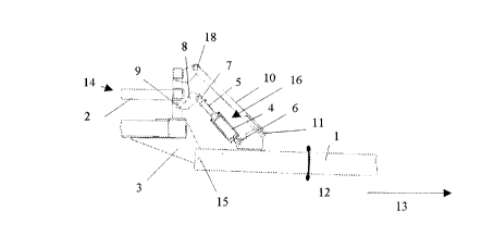
CLAIM 8. A tractor-trailer hitching apparatus, wherein:
the apparatus includes an elongate tow-bar;
the tow-bar, in operation of the apparatus, is in a floating configuration
relative to the tractor and trailer, in that the apparatus includes a
pitch-mode pivot connection A between the tow-bar and the trailer,
and includes a pitch-mode pivot connection B between the tow-bar
and the tractor;
the pivot connection A being such that, in operation of the apparatus, the
trailer can pitch-pivot relative to the tow-bar about the pivot
connection A, whereby, during pivoting, the distance L from a point C
on either the trailer or the tow-bar to a point D on the other of either
the trailer or the tow-bar, being points spaced from pivot A, varies in
length;
when the tractor and the hitched trailer are on flat level ground, the distance
between points C and D is LO;
the apparatus includes a first mechanical link, extending between point C
and point D;
the first mechanical link includes a hydraulic ram, having a fixed-connection
means at one end and a floating connection means at the other end;
the fixed-connection means is a means for fixedly connecting the one end of
the ram to point C;
the floating-connection means is a means for floatingly connecting the other
end of the ram to point D, being a means for guiding and constraining
the said other end of the ram for movement towards and away from
point D;
the apparatus includes a ram travel limit-means;
the ram is extendable in length, upon being supplied with hydraulic pressure,
up to a limit of extension;
the limit of extension is defined by the ram travel limit-means;
the ram is of such dimensions that, at its limit of extension, the distance
between points C and D is greater than LO.


CLAIM 9. Apparatus of claim 8, wherein the ram travel limit means is a
means for limiting the extension of the ram, external to, and
separately from, the piston bottoming in the cylinder of the ram.

CLAIM 10. Apparatus of claim 8, wherein the ram travel limit means
comprises the piston bottoming in the cylinder of the ram.

Description

Note: Descriptions are shown in the official language in which they were submitted.


218~2


DISK OPENER CARRIER HITCH

DESCRIPTION OF THE DRAWINGS

Figure 1 is a cross-section of the hitch shown in working condition.
Flqure 2 is a cross-section of the hitch shown in transport and locked
condition.
Flg 3 shows a plan view of the hitch of the invention in conjunction with a
conventional tractor and implement frame, the components being shown in
an operational condition.
Fig 4 is the same view as Fig 3, the compoents being shown in the transport
condition .

DESCRIPTION OF THE PREFERRED ENMODAENT

Figure I shows the lockina hitch generally designated 14 in working
condition. The direction of travel is indicated at 13.

Figure 2 shows the locking hitch in locked position for transport.

Hitch 1 may be attached to a tractor 19 or other implement such as an air
seeder in a conventional manner (not shown). Hitch 1 is secured to the
fixed extension 3 of tool frame 2 for pivotal movement about transverse axis
15 providing a floating hitch for the tool frame 2 in a conventional manner.

Preferably barrel end 4 of the hydraulic cvlinder 16 is mounted directly to
hitch portion 1 for pivotal movement at connection 6. Rod end 5 of the
hydraulic cylinder 16 is pivotally attached at 7 to floating link 8. Link 8 is
pivotally attached to frame 2 at 9.

Alternatively, the hydraulic cylinder and floating link mav be reversed with

2 1 882 t 2


the barrel end attached to the frame.

During workinc of the implement, cylinder 16 provides for rotation of
floating link 8 at 7 and 9 and the hitch 1 floats by rotation at 15 in the
direction shown at 12. Preferably, no pressure is applied to cylinder 16 and
the hitch floats freely.

For transport, pressure is applied to cylinder 16 and causes extension of rod
5 which, in turn, causes rotation of link 8 at 9 until abutment 8 contacts the
frame 2. Further extension of cylinder 16 causes rotation of hitch 1 about
15. Preferablv the rotation is limited bv the length of the stroke of the
cylinder 1 6.

The hitch is also provided with lockina arm 10 which is pivotally attached to
the frame 2 at 18 and includes a slot 17 for sliding engagement with pin 11
mounted to hitch 1. Locking arm mav be configured to limit the extension of
cvlinder 16 and lock out any floating action of hitch 1 in respect of frame 2
during transport of the implement. Alternatively, slot 17 may be slightly
longer so as to permit the full extension of cylinder 16 to the end of its
stroke.

Preferably rod 5 is provided with a transport lock (not shown) to
mechanically prevent retraction of rod 5 during transport for safety reasons
in the event the hydraulic pressure should fall.

In Fig 4, the hydraulic cylinder has been actuated, i.e extended, whereby the
frame can no longer pivot relative to the hitch about point 15. The fronmt
wheeles of the trailer have been (at least partially) lifted off the ground,
whereby the weight of the front end of the frame now rests on the tractor.
Thus, during towing of the implement for transport (non-working) purposes
the hitch is solid, whereas during working operation the hitch is floating.

Representative Drawing
A single figure which represents the drawing illustrating the invention.
Administrative Status

For a clearer understanding of the status of the application/patent presented on this page, the site Disclaimer , as well as the definitions for Patent , Administrative Status , Maintenance Fee  and Payment History  should be consulted.

Administrative Status

Title Date
Forecasted Issue Date Unavailable
(22) Filed 1996-10-18
(41) Open to Public Inspection 1998-04-18
Dead Application 2001-10-18

Abandonment History

Abandonment Date Reason Reinstatement Date
2000-10-18 FAILURE TO PAY APPLICATION MAINTENANCE FEE

Payment History

Fee Type Anniversary Year Due Date Amount Paid Paid Date
Application Fee $0.00 1996-10-18
Maintenance Fee - Application - New Act 2 1998-10-19 $100.00 1998-10-16
Maintenance Fee - Application - New Act 3 1999-10-18 $100.00 1999-09-09
Owners on Record

Note: Records showing the ownership history in alphabetical order.

Current Owners on Record
GEREIN, MARK ANTHONY
Past Owners on Record
None
Past Owners that do not appear in the "Owners on Record" listing will appear in other documentation within the application.
Documents

To view selected files, please enter reCAPTCHA code :


To view images, click a link in the Document Description column. To download the documents, select one or more checkboxes in the first column and then click the "Download Selected in PDF format (Zip Archive)" or the "Download Selected as Single PDF" button.

List of published and non-published patent-specific documents on the CPD .

If you have any difficulty accessing content, you can call the Client Service Centre at 1-866-997-1936 or send them an e-mail at CIPO Client Service Centre.


Document
Description 
Date
(yyyy-mm-dd) 
Number of pages   Size of Image (KB) 
Cover Page 1998-09-14 1 24
Abstract 1997-03-11 1 6
Cover Page 1997-03-11 1 15
Description 1997-03-11 2 71
Claims 1997-03-11 4 107
Drawings 1997-03-11 4 60
Representative Drawing 1998-09-14 1 5
Cover Page 1999-09-30 1 24
Fees 1999-09-09 1 30
Fees 1998-10-16 1 34
Office Letter 1996-11-27 1 30
PCT Correspondence 1996-12-10 1 29