Note: Descriptions are shown in the official language in which they were submitted.
2 1 88222
ACTIVATED CARBON HONEYCOMBS HAVING VARYING
ADSORPTION CAPACITIES AND METHOD OF MAKING SAME
This invention relates to activated carbon bodies in
the shape of honeycomb structures. The honeycombs are made
by contacting a crosslinkable resin with channel-forming
material and optionally with pore-forming and/or support
fillers, shaping, curing, carbonizing, and activating. The
channel-forming material breaks down into low molecular
weight components in inert atmosphere at high
temperatures, leaving behind the honeycomb channels. These
bodies are strong and are not subject to attrition as are
granulated carbon beds. The bodies have continuous flow
paths for minimizing pressure drop in a flow stream. The
configuration of the channels, and hence the adsorption
capacity can be controlled by selection of suitable size
and shape channel-forming material as well as percentage
of pore-forming and support fillers. Therefore the bodies
can be suited to a wide variety of adsorption
applications.
Back~round of the Invention
Activated carbon materials in the form of granules or
powders are used for a variety of pollution control
applications. Pollutants in liquid or gas streams are
removed by contacting the stream with activated carbon in
granulated or powdered form. The fine angstrom size pore
2 21 88222
structure of activated carbon enables adsorption of the
impurities out of the process streams. The pores in
activated carbon which impart the unique ability to adsorb
the pollutants even at very low concentrations (eg., as
low as 1 ppm) are in the 5 to 20 angstrom range. Pores
above about 50 angstroms do not contribute significantly
to adsorption at low concentrations.
Although activated carbon is used in many pollution
control applications, in the form of pellets or powder, a
major disadvantage with this form of carbon is the high
pressure drop associated with packed beds of pellets or
powder. Another problem is that of entrainment of the
powder in the flow stream and attrition of the granules.
One way around this problem is to form the activated
carbon in the shape of a honeycomb. The honeycomb geometry
has the advantage of high geometric surface area available
for contact and low pressure drop across the bed. In some
industrial processes honeycomb geometries are necessary.
Resins have been used in making carbon bodies both as
binders and as carbon precursors. For example, phenolic
resins are extruded into honeycomb shapes as in U.S.
patent 4,399,052. The resin is cured, carbonized, and
activated. A major difficulty with such a product is that
during carbonization when about 50 wt.% is lost, such
bodies distort and crack in many cases.
All of the above difficulties are overcome by the
-process of coating a porous ceramic honeycomb body with a
thermosetting resin, and then carbonizing and activating.
Such products are described in U.S. application SN
08/11,385, filed January 29, 1993. The drawbacks
associated with this process are the cost of first
extruding and then firing a ceramic honeycomb and then
coating, curing, and activating. Secondly the amount ~f
resin and hence the amount of carbon that can be put on
the body is limited, thus limiting its capacity.
3 21 88222
Methods of making shapes by dipping rods or cylinders
in resin and then forming honeycombs by removing the rods
after curing the resin as in U.S. patents 3,825,460 and
3,922,412, again are subject to the same type of problems
such as warping and cracking as the bodies formed by
extrusion of resin.
It would be highly desirable to have a method in which
the adsorption capacity per unit volume can be controlled
so that it can be made to fit the requirements of a
specific application and at the same time exhibit
properties in the body of no attrition, minimized pressure
drop, and high surface area in a given volume.
The present invention provides such a carbon structure
and a method of making it.
Sllmm~ry of the Invention
In accordance with one aspect of the invention, there
is provided an activated carbon body having flow-through
channels. Among other shapes the channels can be straight,
curved or crisscrossed.
In accordance with another aspect of the invention,
there is provided a method for making an activated carbon
body having flow-through channels. The method involves
combining and shaping channel-forming material and
optionally fugitive pore-forming material and non-fugitive
support material, a crosslinkable resin into a green body
and curing the resin. The temperature at which the
channel-forming material begins to distort is greater than
the curing temperature of the resin. The resin is
carbonized and at the same time the channel-forming
material is vaporized out to form a carbon body having
flow through channels in the configuration of the fugitive
material. The carbon body is then activated.
4 21 8822~
Rrief Description of the Dr~wings
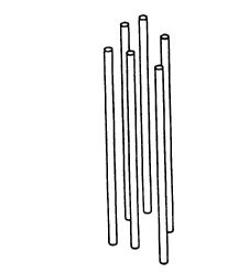
Figure 1 shows an array of channel forming elements in
the form of straight solid filaments.
Figure 2 shows an array of channel forming elements in
the form of curved solid filaments.
Figure 3 shows an array of channel forming elements in
the form of straight hollow tubes.
Figure 4 shows a honeycomb body shaped from a mixture
of resin and loose solid fibers or filaments, for example
of the types shown in Figures 1 or 2.
Figure 5 shows the honeycomb of Figure 4 after
carbonization.
Figure 6 shows a carbonized honeycomb body made using
hollow tubular filaments, for example of the type shown in
Figure 3.
Figure 7 shows channel-forming material in the form of
a fused screen.
Figure 8 shows channel-forming material in the form of
a woven screen.
Figure 9 shows resin in contact with a screen in the
dried and still formable state.
Figure 10 shows the resin and screen shape of Figure 9
further shaped into a roll.
Det~ile~ Description of the Invention
The present invention relates to carbon bodies or
structures for which the adsorption capacity per unit
volume can be controlled, that is, can be made to be low,
intermediate or high depending on what the specific
application requires. The structure also eliminates
problems such as attrition associated with granulated
beds, and the pressure drop is lower than in granulated
beds.
The carbon body is characterized by a honeycomb
5 218822~
structure, that is, having flow-through channels for
optimum flowability of a work stream therethrough; and
angstrom sized pores (about 5 to about 50 angstroms for
adsorption). The channels can be straight and/or curved.
The channels can be essentially parallel, and/or non-
parallel, and/or crisscrossing. The structure exhibits
high strength.
The bodies of the present invention are suited for use
in any of a wide variety of applications for which
activated carbon bodies have been used in the past.
Examples of such applications include residential water
purification, volatile organic compound emission control,
natural gas fuel storage for gas-powered vehicles or
equipment, indoor air purification, industrial
respirators, automotive cabin air filters, ventless hoods,
chemical separations, NOX and SO~ control, and exhaust
traps for automotive cold start applications. Other
potential applications include use as ozone filters,
mercury collection from municipal incinerators, radon
adsorption, automotive gas tank or intake manifold
emissions, sewer pump vents, oil-air separations, or any
other application wherein adsorption of a component or
components from a fluid stream containing multiple
components is desired.
The method for making the structures involves
contacting a continuous fugitive material or channel-
forming material with a crosslinkable resin and optionally
with what will be called fillers. The fillers can be non-
fugitive or support material to enhance strength of the
body, and/or non-continuous fugitive or pore-forming
material which forms wall porosity during carbonization.
The mixture is then shaped into a form by a non-extrusion
process. The form is then dried, and the resin is cured
and carbonized to produce a carbon body. After the drying
step, the form can be further shaped if necessary. During
6 21 882~
carbonization, the fugitive materials vaporize. The
channel-forming material leaves behind channels which are
essentially in the same shape as they were in the pre-
carbonized form. The pore-forming material, if present
leaves behind wall porosity. The carbonized body is then
activated to produce the final activated carbon body.
The resin content determines the total amount of
carbon in the body structure. The size, shape and weight
percent of channel-forming and pore-forming material
determines the surface area of the carbon available for
activation which in turn determines the adsorption
capacity. Support material controls the strength and cost
of the body.
The adsorption capacity is controlled by the amount of
lS carbon present in the final body structure and the
percentage of this carbon available for activation. The
percentage of carbon available for activation is
determined by the available surface area for the
activation reaction. The available surface area in turn is
determined by the channel-forming and pore-forming
material. If surface area is increased excessively then
the structure can become weak. The support fillers enhance
strength and allow maximization of surface area. The
method of the present invention allows control of surface
area available for adsorption for a given weight of
carbon.
The resin
A critical characteristic of the resin is that it be
crosslinkable. These resins form three-dimensional network
structures extending throughout the final body. The final
body is stable to heat and cannot be made to melt or flow.
Examples of resins that can be considered suitable to the
practice of the present invention are the thermosetting
resins such as phenolics, furan, epoxies, and
7 2 1 88~2~
thermoplastic polymers such as polyacrylonltrile,
polyvinyl chloride, etc., which although not
thermosetting, can be crosslinked by high temperature
oxidation. It is desirable that the resin give a high
carbon yield on carbonization, that is, for example at
least about 25%, and preferably at least about 40~ based
on the amount of cured resin. Thermosetting resins
normally give these high yields. Thermosetting resins are
the preferred resins. Examples of thermosetting resins
that can be used in the practice of the present invention
are phenolics, furan, epoxies, and combinations of these.
Preferred resins are phenolics, furan, and combinations of
these because of their high carbon yield and low
viscosities at room temperature. Normally, the viscosities
can vary from about 50 cps to about 1000 cps. The
preferred viscosities are about 100 to about 500 cps. The
resins can be provided as solids, liquids, solutions, or
suspenslons .
One resin that is especially suited to the practice of
the present invention is phenolic resole. The phenolic
resoles are solutions of phenolics in water. A higher
viscosity suspension of solid phenolic powder in liquid
resin can be used to increase the amount of resin in the
support material (when used) and thus the final carbon
yield. One especially suited resin is a phenolic resole
resin available from Occidental Chemical Corporation,
Niagara Falls, N.Y. under the product name of Plyophen
43290. According to OxyChem~ Material Safety Data Sheet
No. M26359, Plyophen 43290 is a liquid one step phenolic
resin containing phenol, formaldehyde, and water, having a
specific gravity of 1.22-1.24, a boiling point >100~C and
a pH of 7.5-7.7 ~ 100 gm/l.
Furan resins are available as liquids. One furan that
is suitable to the practice of the present invention is
supplied by QO Chemicals, Inc. under the name of Furcarb@
8 2 1 88222
LP. According to the Material Safety Data Sheet by QO
Chemicals, Inc., Furcarb~ LP resins preparations of phenol
(4% max) in furfuryl alcohol, and have a specific gravity
of 1.2, and a boiling point of 170~C. The viscosity is 300
S cps.
The ch~nnel-for~ing m~teri~l
The channel-forming material volatilizes and leaves
very low or no residue at the temperatures of the present
invention. For example, the material breaks down into low
molecular weight volatile compounds during firing in an
inert atmosphere leaving very little or no residue.
The channel-forming material must have a heat
distortion temperature point which is greater than the
curing temperature of the resin that is used so that it
does not distort during the curing process. This is
typically but not necessarily at least about 150~C which is
the cure temperature for phenolic resins.
The channel-forming material is continuous, that is,
filament or fiber-like and is of sufficient length to
provide on its volatilization, low pressure drop paths or
channels through which a work stream can pass in
continuous uninterrupted flow through the body; as opposed
to wall porosity.
The channel-forming material can be in any form that
will provide these low pressure drop paths, such as
fibers. For example, the fibers can be in the form of a
plurality or array of loose fibers or filaments, or in the
form of a very long monofilament which is wound in a given
configuration with the length and diameter being chosen
depending on the amount and configuration of porosity that
is desired. The fibers can range typically from about 1
micrometer or less in diameter to as much as 1/2
centimeter or 1 centimeter or more in diameter depending
on the application. The fibers can be solid or hollow with
9 21 88222
commercial plastic straws being one example of the latter.
The fibers can also be preformed into a shape such as
woven or non-woven (fused) mats or screens, etc.
Figures 1, 2, 3, 7, and 8 show some common shapes of
channel-forming materials used in the practice of the
present invention and hence, the configurations of
channels in the bodies of the present invention.
Figures 1, 2, and 3 show fiber-like materials.
An array of channel forming elements in the form of
loose straight solid filaments is shown in Figure 1.
An array of channel forming elements in the form of
loose curved solid filaments is shown in Figure 2.
An array of channel forming elements in the form of
loose straight hollow tubes is shown in Figure 3.
Figure 7 and 8 show preformed shapes.
Figure 7 shows a fused screen (70) in which after
carbonization the openings (72) between the screen area
(74) will be the carbon while area (74) will form the
channels.
Figure 8 shows a woven screen (80) in which after
carbonization the openings t82) between the screen area
(84) will be the carbon while area (84) will form the
channels.
Since the flow-through channels of the body take on
the shape of the fugitive material in the pre-carbonized
body, the fugitive material is preferably non-wettable by
the resin l-quid, solution or suspension in order that
channels of clean and defined shape will form on
vaporization.
Therefore, the nature, amount, size, and shape of the
continuous fugitive material are chosen depending on the
desired degree and configuration of channels desired in
the final body. The above factors also determine surface
area of carbon available for adsorption.
Some materials that are especially suited as fugitive
lo 2 1 88222
materials are thermoplastics. Examples of thermoplastics
are polymers which on carbonization in inert atmosphere
break down into low molecular compounds and disappear
without leaving any residue. Examples of these materials
are polyester, polypropylene. One such thermoplastic
polymer is a polypropylene which is supplied in the form
of a monofilament by Glassmaster Inc., Lexington, S.C.
One suitable continuous fugitive material is
polypropylene which can be in the form of fibers or
screens. Fibers are supplied by Glassmaster, Lexington,
S.C.. Screens of various mesh sizes are
supplied by Tetko, Inc. Briarcliff Manor, N.Y.
Any size, shape, or chemistry combination of channel-
forming materials and filler materials can be used.
In accordance with one embodiment, a body is produced
having a honeycomb structure which is formed from an array
of fibers or a screen of channel-forming material.
Filler ~ditives
Additionally, filler material can be contacted with
the resin and channel-forming material. The filler
material can be pore-forming or support or çombinations of
the two types.
Pore-forming material is essentially the same as far
as chemical composition as channel-forming material but
the relative sizes and shapes of the two types vary.
Material that will form flow thru-channels in a given size
body is termed channel-forming for that body. Material
that is not large enough in size to form channels in a
given size body, but will form porosity is termed pore-
forming material.
As with channel-forming materials, the pore-forming
material is preferably non-wettable so that pores of ~lean
and defined shape form on vaporization.
One material that is especially suited for use as
11 2 1 8822~
pore-forming material in the practice of the present
invention is finely powdered polymer fibers such as
polyester flock supplied by International Filler Corp.,
North Tonawanda, N.Y., under the designation 31WPF. Flock
is formed by grinding continuous fibers of thermoplastic
material to very small size so that the material appears
to be powdery. The fiber lengths in flock materials are
typically less than about 150 micrometers.
As with channel-forming material, the nature, amount,
size, and shape of the pore forming material are chosen
depending on the desired size and amount of porosity
desired in the final body. The above factors also
determine surface area of carbon available for adsorption.
By non-fugitive or support is meant that the material
is non-reactive, non-volatile, and remains essentially
unchanged throughout the steps of the process and intact
as part of the final product body, as opposed to fugitive
or burnout materials. The non-fugitive material serves as
a support for the carbon and contributes to the strength
of the body. Some support materials are cordierite, eg.,
cordierite powder, clays, glass powders, alumino-silicate,
sand, and combinations of these. Some preferred support
materials are cordierite, clays, glass powders, alumino-
silicate and combinations of these. Especially preferred
is cordierite powder because of its low cost when a
casting process is used.
The support material can be in the form of a mat for
especially good facility in shaping and to provide a
closely knit or strong support for the resin and
subsequently the carbon. The mat is made preferably from
short fibers but in some cases longer fibers can be used
to attain a given configuration in the final product body.
Also for forming mats, it is preferred that the fibers be
about 1-50 and more preferably about 2-10 micrometers in
diameter. The mats are of low bulk density (high void
12 2 1 8822~
volume). The void volume can vary from about 50% to about
98%. Preferred void volumes are about 75-95%.
It is preferred that the support mat be capable of
absorbing at least about three times its weight and more
preferably at least about five times its weight in resin
when contacted therewith.
One preferred support mat is of alumino-silicate
fibers, especially in the form of short fibers, such as
Fiberfax 970 fiber mat supplied by Carborundum Co.,
Niagara Falls, N.Y.
The resin is contacted with the channel-forming
materials and with any fillers that are being used and the
material is shaped into a green body. By green body
according to the present invention is meant the shaped
body before any curing of the resin. The contacting can be
done by any technique designed to bring the materials
together and form into the desired shape, such as for
example dipping the solid components as the screens and
fibers into the resin in static or continuous processing.
Conventional molding techniques are well suited for the
purposes of the present invention. The green body is
heated to dry and cure the resin.
The drying is done to remove the liquid phases, eg.,
solvents, etc., therefrom. The drying advances the resin
to a non-tacky but still flexible state, commonly called
the "B stage". At this stage, partial crosslinking in the
resin takes place. The drying conditions of temperature
and time are chosen depending on the combination and
amounts of resin and support material although typical
drying temperatures are in the range of about 80~C-110~C.
The drying conditions can be adjusted as necessary to
achieve the "B" stage.
For example, in the case of phenolic resole resin,
water, the solvent is removed by drying at about 80~C-85OC,
and then at about 100~C-110~C for a total time of up to
13 2 1 88222
about 3 hours. For example for a 2-3 mm thick sheet or mat
of alumino-silicate fibers impregnated with resin, the
drying time is about 1.5-2 hours at about 80~C-85~C and
then about 20-30 minutes at about 100~C-110~C to obtain the
S flexible non-tacky state. At this stage if screens or mats
both fugitive and non-fugitive are used or made, they can
be further shaped if desired. For example the screens can
then be cut, stacked, and the cut pieces pressed together
to further shape the dried body, or they can be rolled,
etc.
Some suitable techniques for contacting, shaping and
drying are described below, although it is to be
understood that the invention is not limited to such.
1) One technique is to form a wet mixture of all the
components: resin, channel-forming material in the form of
loose fibers, and optionally the fillers: pore-forming
and/or support. The mixture can then be shaped by
introducing the components into a mold.
2) Another technique is to use channel-forming fibers
in the form of a screen, eg., of thermoplastic polyester,
polypropylene, etc. and optionally pore-forming material
in the form of loose very short fibers, eg. L polyester
flock, etc. In this case, the resin is mixed with the
pore-forming material if used, and the mix is then poured
into a mold in which the screen has been placed. Figure 9
shows a dried body (90) having a screen (92) such as of
the type shown in Figures 7 or 8 in contact with resin
(94) which has been dried to the B stage. The dried resin
and screen can be further shaped. Figure 10 shows the
further shaping of this dried body into a roll.
3) The resin can be mixed with a support material
eg., cordierite powder, and this mix poured into a mold in
which has been placed a structure of channel-forming
material such as a screen.
4) The support material can be pre-shaped and then
14 21 88222
contacted with the resin. Channel-forming material can be
pressed into the preshaped material. For example, resin
can be contacted with a support mat eg., of alumino-
silicate, and dried, after which channel-forming fibers
are pressed into the resin-support mat.
5) Channel-forming material can be pre-shaped and
then contacted with the resin. Support material can be
pressed into the preshaped material.
6) Channel-forming material in the form of a
monofilament, eg., made from a thermoplastic polymer as
polypropylene can be pulled through a resin bath, eg., a
phenolic resin bath to coat the monofilament with the
resin. Optionally, filler material pore-forming and/or
support material and/or solid resin can be included in the
resin bath. At this point, the resulting coated
monofilament can optionally be passed through a die with a
cylindrical hole to remove excess resin on the
monofilament. In any case, the coated monofilament is then
wound onto a drum with a flat or round cross section. In
this way, layers of the monofilament can be built up on
the drum by continuous winding. After the thickness of
monofilament is built up to the desired level on the drum,
the winding operation is discontinued and the layers are
taken off the drum and can be further shaped such as by
pressing, into the shaped green body. The green body dried
and the resin cured. Alternately, the drying can be done
on the drum. The dried form can then be further shaped if
desired.
In some cases the support material, if used, can be
first impregnated with a catalyst which is known to
accelerate the curing reaction, and then mixed with the
resin. On pouring into the mold, the resin becomes rigid
and a cured body can be formed. An example of this process
is the case of furan resin cured with catalysts such as
ZnCl2, PTSA (para-toluene sulfonic acid), citric acid, or
1S 2 1 88222
some other catalyst.
If the shaping was done by molding, the mold with the
green body is heated to dry the green body and cure the
resln .
After the body has been shaped into the desired shape,
the resin is then finally cured in the shaped form by
heating under the specific temperature and time conditions
required for the specific resin. This can be found in the
manufacturer's literature. For example, for phenolic
resole 43290 from Occidental Chemical Co. the body is
heated in air to about 140-155~C. The final temperature is
attained slowly so that the body does not distort. For
example, the body is first heated to about 90~C-100~C, then
to about 120~C-130~C and held at this temperature for about
1-2 hours. It is then heated to about 140~C-155~C and held
for about 30 minutes-2 hours for final cure.
The rigid shape taken by the resin during the
previously described shaping which is done at low
temperatures, is not distorted during the curing.
Figure 4 shows a honeycomb body (40) shaped from a
mixture of resin (42) and loose solid fibers or filaments
(44) for example of the types shown in Figures 1 or 2.
The resulting cured resin shaped body is then
carbonized and activated to convert the resin to activated
carbon. The carbonization also results in removal of the
fugitive materials to form the respective shapes of
channels and wall porosity.
The carbonization is carried out by heating the body
in an inert or reducing atmosphere such as nitrogen or
argon or forming gas. Forming gas is a mixture of nitrogen
and hydrogen. Typical mixtures by volume are 92:8 or 94:6
N2:H2, although any mixtures can be used. Carbonization
temperatures are about 600~C-1000~C or more typically about
700-1000~C for a length of time of usually about 1-20
hours. While the body is in the temperature range of about
16 21 88222
300-600~C, the fugitive materials vaporize. During
carbonization low molecular weight compounds separate out
and carbon atoms form graphitic structures. For example
for phenolic resole resin 43290 from Occidental Chemical
Co. and Furan Furcarb resin from QO Chemicals,
carbonization is done by heating at a rate of about
150~C/hr in N2. The temperature is held at about 900~C for
about 6-10 hours to complete the carbonization. The
temperature is then reduced to 25~C at a cooling rate of
about 150~C/hr. On carbonization, the body contains random
three dimensional oriented graphitic platelets with
amorphous carbon between the platelets.
Figure S shows the honeycomb of Figure 4 after
carbonization (50). The channel forming material has
burned out to leave flow through channels (52) in the
carbon structure (54).
Figure 6 shows a carbonized honeycomb body (60) made
using hollow tubular filaments for example of the type
shown in Figure 3. The tubular filaments have burned out
to leave the channels (62).
The carbon in the body is then activated by partially
oxidizing in a suitable oxidant such as CO2, steam, air, o-c
a combination of these, etc. Activation can be carried out
at temperatures between about 700~C-1000~C. Activation
conditions depend on type and amount of resin, flow rate
of gas, etc. For example for phenolic resole and Furcab
resins activation conditions are at about 900~C for about 1
hour in CO2 at a flow rate of about 14.2 l/hr. (about 0.5
CFH (cubic feet per hour)). The partial oxidation during
activation causes the removal of the amorphous carbon and
the formation of molecular size porosity between the
graphitic platelets. This porosity and the graphitic
platelets impart the adsorption characteristics to the
resulting activated carbon body.
In accordance with another embodiment, resin-
17 2 ~ 88222
containing mats having pore-forming material can be broken
up in granules of various sizes suitable to the
application. Breaking up of the mats is done at any point
in the process after curing. For example, it can be done
either after curing and before carbonizing, or after
carbonizing and before activating, or after activating.
The granules are then subjected to the remainder of steps
thru activation to form a carbon composite. Such granules
have high surface area due to the pores formed on the
burn-out of the pore-forming material.
The activated carbon body of the present invention is a
continuous carbon structure and thus is high in strength.
To more fully illustrate the invention, the
following non-limiting examples are presented. All parts,
portions, and percentages are on a weight basis unless
otherwise stated.
Example 1
Continuous polypropylene fibers were introduced into
liquid phenolic resole and the resulting mixture was then
dried and cured at about 80~C for about 2 hours, about
100~C for about 1 hour, and about 150~C for about 30
minutes. The compact solid was then carbonized at about
900~C for about 6 hours in nitrogen. At the end of
carbonization, the compact was a honeycomb structure with
continuous paths in place of the polypropylene fibers. The
carbon was then activated at about 900~C for about 1 hour
in carbon dioxide. The 1" (2.54 cm) diameter x 1" (2.54
cm) long honeycomb had a butane adsorption capacity of
about 800 mg.
Example 2
A mixture of phenolic resole resin 43290 from
Occidental Chemical Co., a solid phenolic powder from the
same company No. 7716, and polyester flock (finely
powdered polymer fiber 31WPF from International Filler
Corp), in the weight ratio of 77.4%, 15.5%, and 7.2~
18 21 88222
respectively was made and poured into a mold containing
continuous polypropylene fibers. The mold was then heated
to about 80~C and dried and then slowly heated to about
125~C and held for about 1 hour and then heated in nitrogen
to about 900~C and held at that temperature for about 6
hours. During heat-up and carbonlzation both the
polypropylene and the polyester fibers disintegrated and
disappeared leaving holes behind. A honeycomb shape with
straight parallel channels was thus formed. This
honeycomb's walls were also porous allowing for
maximization of surface area. This honeycomb was activated
in carbon dioxide at about 900~C. This honeycomb of the
same size as that in Example 1 gave a butane adsorption
capacity of about 345 mg.
Fx~ple 3
A mixture of about 13.8% aluminosilicate Fiberfrax
fiber from Carborundum Corp., about 14% Polyflock 31WPF
from international Filler Corp., about 20.4% 7716, and
about 51.8% 43290 phenolic resin from Occidental Chemical
was poured into a mold containing polypropylene fiber of
about 1 mm in diameter. The resin was cured at about 150~C
as in Example 2 and carbonized and activated as before to
obtain a carbon honeycomb structure the same size as that
of example 1. The butane adsorption capacity of this body
was about 525 mg.
Fxample 4
A mixture of about 6.2% polyflock, about 13.8~ 7716
solid phenolic resin and about 69% 43290 liquid phenolic
resin from Occidental Chemical, and about 11% fiberfrax
fiber from Carborundum was mixed and poured into a mold
containing alternate 25 mesh and 200 mesh polypropylene
screens from Tetko Inc. The samples were carbonized and
activated as described above to obtain a honeycomb
structure the same size as in the previous examples. The
butane adsorption capacity was about 552 mg.
19 2 1 88222
Fx~mDle 5
Fiberfrax 970 mat from Carborundum Co. was dipped in
resin and then allowed to dry at about 80~C for about 2
hours and about 100~C for about 1 hour. Polypropylene
monofilaments as in Example 3 were then pressed into soft
flexible mat and a preform was made by laying several mats
together and pressing and heating to cure. The preform was
carbonized and activated to obtain a honeycomb structure
the same size as in the previous examples with adsorption
capacity of about 829 mg of butane.
F.x~rr~l e 6
A mixture of about 11~ finely ground cordierite powder
having an average particle size of about 10 micrometers in
diameter, about 6% polyflock, about 13.6~ 7716 resin and
lS about 69.4% 43290 resin from Occidental Chemical was
poured into a mold containing a 25 mesh polypropylene
screen from Tetko Inc. The mold was heated to cure,
carbonize, and activate the resin as in the previous
examples. The body having the same size as in the previous
examples had a butane adsorption capacity of about 565 mg.
The examples show that carbon structures with parallel
flow paths can be made with controlled adsorption
capacities. Depending on the requirements for the product
and the economic considerations, carbon structures
produced can be made to have different adsorption
capacities.
It should be understood that while the present
invention has been described in detail with respect to
certain illustrative and specific embodiments thereof, it
should not be considered limited to such but may be used
in other ways without departing from the spirit of the
invention and the scope of the appended claims.