Language selection

Search

Patent 2188291 Summary

Third-party information liability

Some of the information on this Web page has been provided by external sources. The Government of Canada is not responsible for the accuracy, reliability or currency of the information supplied by external sources. Users wishing to rely upon this information should consult directly with the source of the information. Content provided by external sources is not subject to official languages, privacy and accessibility requirements.

Claims and Abstract availability

Any discrepancies in the text and image of the Claims and Abstract are due to differing posting times. Text of the Claims and Abstract are posted:

  • At the time the application is open to public inspection;
  • At the time of issue of the patent (grant).
(12) Patent: (11) CA 2188291
(54) English Title: CASING TUBE WITH CASING SHOE
(54) French Title: TUBE DE CUVELAGE DOTE D'UN SABOT DE TUBAGE
Status: Deemed expired
Bibliographic Data
(51) International Patent Classification (IPC):
  • E21B 17/14 (2006.01)
  • E21B 7/20 (2006.01)
  • E21B 17/00 (2006.01)
(72) Inventors :
  • EKSTROM, ROSS CHRISTIAN (Sweden)
(73) Owners :
  • ATLAS COPCO CRAELIUS AB (Sweden)
(71) Applicants :
  • ATLAS COPCO CRAELIUS AB (Sweden)
(74) Agent: FETHERSTONHAUGH & CO.
(74) Associate agent:
(45) Issued: 2005-05-31
(86) PCT Filing Date: 1995-04-21
(87) Open to Public Inspection: 1995-11-02
Examination requested: 2002-04-09
Availability of licence: N/A
(25) Language of filing: English

Patent Cooperation Treaty (PCT): Yes
(86) PCT Filing Number: PCT/SE1995/000434
(87) International Publication Number: WO1995/029321
(85) National Entry: 1996-10-18

(30) Application Priority Data:
Application No. Country/Territory Date
9401349-7 Sweden 1994-04-21

Abstracts

English Abstract


Casing tube with casing shoe for use at drilling in earth layers or
rock by means of impact drilling comprising a casing shoe (5) of metal
and a casing tube (4) of plastic. The casing shoe is provided with threads
(31), groove (33) or flanges which lock the casing shoe (5) to the casing
tube to create a unit. The casing shoe is provided with a tube-formed
extension (32) in order to protect the casing tube from damages from drill
cuttings.


French Abstract

Tube de cuvelage doté d'un sabot de tubage destiné à être utilisé pour le forage à percussion dans des couches de terre ou de la roche. Ledit tube comporte un sabot de tubage (5) métallique et un tube de cuvelage (4) en plastique. Le sabot de tubage présente des filets (31), une rainure (33) ou des rebords qui bloquent ce dernier sur le tube de cuvelage de manière à former une unité. Le sabot de tubage est doté d'une extension tubulaire (32) destinée à empêcher que le tube de cuvelage ne soit endommagé par les copeaux de forage.

Claims

Note: Claims are shown in the official language in which they were submitted.


3
CLAIMS:
1. Casing tube with casing shoe for use at drilling
in earth layers or rock by means of impact drilling
comprising a casing shoe of metal and a casing tube of
plastic fastened to the casing shoe, whereby the casing shoe
has a part turned away from the casing tube and having
substantially the same outer diameter as the casing tube,
and a part with reduced diameter to which the casing tube is
fastened, characterized in that the part with reduced
diameter is provided with threads of opposite pitch for
locking said casing shoe to said casing tube.
2. Casing tube with casing shoe for use at drilling
in earth layers or rock by means of impact drilling
comprising a casing shoe of metal and a casing tube of
plastic fastened to the casing shoe, whereby the casing shoe
has a part turned away from the casing tube and having
substantially the same outer diameter as the casing tube,
and a part with reduced diameter to which the casing tube is
fastened, characterized in that the part with reduced
diameter is provided with grooves for locking said casing
shoe to said casing tube.
3. Casing tube with casing shoe for use at drilling
in earth layers or rock by means of impact drilling
comprising a casing shoe of metal and a casing tube of
plastic fastened to the casing shoe, whereby the casing shoe
has a part turned away from the casing tube and having
substantially the same outer diameter as the casing tube,
and a part with reduced diameter to which the casing tube is
fastened, characterized in that the part with reduced
diameter is provided with flanges for locking said casing
shoe to said casing tube.

4
4. Casing tube with casing shoe for use at drilling
in earth layers or rock by means of impact drilling
comprising a casing shoe of metal and a casing tube of
plastic fastened to the casing shoe, whereby the casing shoe
has a part turned away from the casing tube and having
substantially the same outer diameter as the casing tube,
and a part with reduced diameter to which the casing tube is
fastened, characterized in that the part with reduced
diameter is provided with threads with variable pitch for
locking said casing shoe to said casing tube.
5. Casing tube with casing shoe according to any one
of claims 1 to 4, characterized in that the casing shoe is
provided with a tubeformed extension which extends into the
casing tube to protect the casing tube from being damaged by
drill cuttings at the transition between casing shoe and
casing tube.

Description

Note: Descriptions are shown in the official language in which they were submitted.


CA 02188291 2004-08-25
29312-9
1
Casina tube with casina shoe
The present invention relates to a casing tube
with casing shoe, usually called starting tube, for use at
drilling through earth layers or rock by means of impact
drilling.
In a prior art device, see WO 93/17215, a casing
shoe of metal provided with holes filled with plastic from
the casing tube is used. A drawback with this design is
that it is difficult to join long casing tubes with the
casing shoe in a one step process. Another drawback is that
drill cuttings can hurt the casing tube prematurely at the
transition to the casing shoe. The drill cuttings exert a
certain blasting caused by change of direction of the
cuttings flow in this section.
The present invention, aims at making it possible
to join casing tubes of normal length to the casing shoe in
a one step process. This is achieved by providing the
casing shoe with threads, grooves or flanges adapted to grip
into the plastic material of the casing tube so as to lock
the casing shoe in the plastic material against axial
movement and/or rotation relative to the casing tube. This
makes it possible to shrink the casing tube on the casing
shoe without making the plastic material liquid, which is
necessary if the plastic material is to flow through holes
in the casing shoe and join on the inside thereof. With the
invention it is also possible to use extrusion, casting or
other methods for joining casing shoe and casing tube.
According to a broad aspect, the invention
provides casing tube with casing shoe for use at drilling in
earth layers or rock by means of impact drilling comprising
a casing shoe of metal and a casing tube of plastic fastened


CA 02188291 2004-08-25
29312-9
la
to the casing shoe, whereby the casing shoe has a part
turned away from the casing tube and having substantially
the same outer diameter as the casing tube, and a part with
reduced diameter to which the casing tube is fastened,
characterized in that the part with reduced diameter is
provided with threads of opposite pitch for locking said
casing shoe to said casing tube.
According to another broad aspect, the invention
provides casing tube with casing shoe for use at drilling in
earth layers or rock by means of impact drilling comprising
a casing shoe of metal and a casing tube of plastic fastened
to the casing shoe, whereby the casing shoe has a part
turned away from the casing tube and having substantially
the same outer diameter as the casing tube, and a part with
reduced diameter to which the casing tube is fastened,
characterized in that the part with reduced diameter is
provided with grooves for locking said casing shoe to said
casing tube.
According to a further broad aspect, the invention
provides casing tube with casing shoe for use at drilling in
earth layers or rock by means of impact drilling comprising
a casing shoe of metal and a casing tube of plastic fastened
to the casing shoe, whereby the casing shoe has a part
turned away from the casing tube and having substantially
the same outer diameter as the casing tube, and a part with
reduced diameter to which the casing tube is fastened,
characterized in that the part with reduced diameter is
provided with flanges for locking said casing shoe to said
casing tube.
According to a further broad aspect, the invention
provides casing tube with casing shoe for use at drilling in
earth layers or rock by means of impact drilling comprising


CA 02188291 2004-08-25
29312-9
lb
a casing shoe of metal and a casing tube of plastic fastened
to the casing shoe, whereby the casing shoe has a part
turned away from the casing tube and having substantially
the same outer diameter as the casing tube, and a part with
reduced diameter to which the casing tube is fastened,
characterized in that the part with reduced diameter is
provided with threads with variable pitch for locking said
casing shoe to said casing tube.
According to an advantageous embodiment of the
invention the casing shoe is provided with a tubeformed
extension which extends into the casing tube behind its
joint with the casing shoe. This extension prevents the
drill cuttings from damaging the case tube at the transition
between casing shoe and casing tube by preventing drill
cutting from being pressed against the casing tube by a
relatively to the casing tube rotating guide for the drill
bit.
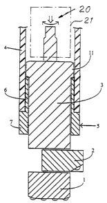
An embodiment of the invention is described below
with reference to the accompanying drawings in which fig 1
schematically shows a drilling device in which the invention
forms a part. Fig 2 shows on a larger scale a casing tube
with casing


2188271
WO 95129321 PCTlSE95/00434
2
shoe according to the invention.
The drilling device shown in fig 1 comprises a drill bit comprising a pilot
bit 1 and a
pivotable reamer 2. The drill bit is exerted to impacts from a guide 3
arranged in a
down-the-hole drilling machine 21. The drill bit is pressed against the ground
and
rotated in the usual way as indicated by the arrows 20. A casing tube with
casing
shoe comprising a casing shoe 5 and casing tube 4 connected with the casing
shoe is
driven into the ground, which can be an earth layer or rock or another similar
material, by hitting the upper part of the casing shoe with a flange 11 on the
guide 3.
Instead of a down-the-hole drilling machine one can use a top hammer drilling
machine outside the drill hole. The casing shoe comprises a part 7, turned
away from
the casing tube 4, with substantially the same outer diameter as the casing
tube and a
part 6 with reduced diameter. Part 6 is on its outer side provided with
threads 31, in
the shown example both left hand threads and right hand threads, i.e. threads
with
opposite pitch, and a groove 33. Alternatively one can provide the casing shoe
with
only grooves and/or flanges or threads with variable pitch to lock the casing
tube to
the casing shoe. In order to fasten a casing tube of normal length to the
casing shoe
one can suitably warm the end of the tube so that it is widened and then press
the
casing shoe into it. When the casing tube is cooled a connection is obtained
through
cooperation between the plastic material and the threads 31 and the groove 33.
In the prior art device the flow of drill cuttings at the rear end of the
casing shoe in
combination with the rotation of the guide causes blasting of the casing tube.
The
casing shoe according to fig 2 is provided with a tubeformed extension 32
which
prevents drill cuttings from hurting this section.

Representative Drawing
A single figure which represents the drawing illustrating the invention.
Administrative Status

For a clearer understanding of the status of the application/patent presented on this page, the site Disclaimer , as well as the definitions for Patent , Administrative Status , Maintenance Fee  and Payment History  should be consulted.

Administrative Status

Title Date
Forecasted Issue Date 2005-05-31
(86) PCT Filing Date 1995-04-21
(87) PCT Publication Date 1995-11-02
(85) National Entry 1996-10-18
Examination Requested 2002-04-09
(45) Issued 2005-05-31
Deemed Expired 2009-04-21

Abandonment History

There is no abandonment history.

Payment History

Fee Type Anniversary Year Due Date Amount Paid Paid Date
Application Fee $0.00 1996-10-18
Registration of a document - section 124 $0.00 1997-01-30
Maintenance Fee - Application - New Act 2 1997-04-21 $100.00 1997-04-01
Maintenance Fee - Application - New Act 3 1998-04-21 $100.00 1998-03-23
Maintenance Fee - Application - New Act 4 1999-04-21 $100.00 1999-03-19
Maintenance Fee - Application - New Act 5 2000-04-21 $150.00 2000-03-16
Maintenance Fee - Application - New Act 6 2001-04-23 $150.00 2001-03-06
Maintenance Fee - Application - New Act 7 2002-04-22 $150.00 2002-03-07
Request for Examination $400.00 2002-04-09
Maintenance Fee - Application - New Act 8 2003-04-21 $150.00 2003-03-07
Maintenance Fee - Application - New Act 9 2004-04-21 $200.00 2004-03-05
Maintenance Fee - Application - New Act 10 2005-04-21 $250.00 2005-03-07
Final Fee $300.00 2005-03-11
Maintenance Fee - Patent - New Act 11 2006-04-21 $250.00 2006-03-06
Maintenance Fee - Patent - New Act 12 2007-04-23 $250.00 2007-03-08
Owners on Record

Note: Records showing the ownership history in alphabetical order.

Current Owners on Record
ATLAS COPCO CRAELIUS AB
Past Owners on Record
EKSTROM, ROSS CHRISTIAN
Past Owners that do not appear in the "Owners on Record" listing will appear in other documentation within the application.
Documents

To view selected files, please enter reCAPTCHA code :


To view images, click a link in the Document Description column. To download the documents, select one or more checkboxes in the first column and then click the "Download Selected in PDF format (Zip Archive)" or the "Download Selected as Single PDF" button.

List of published and non-published patent-specific documents on the CPD .

If you have any difficulty accessing content, you can call the Client Service Centre at 1-866-997-1936 or send them an e-mail at CIPO Client Service Centre.


Document
Description 
Date
(yyyy-mm-dd) 
Number of pages   Size of Image (KB) 
Abstract 1995-04-21 1 32
Description 2004-08-25 4 142
Claims 2004-08-25 2 64
Description 1995-04-21 2 65
Abstract 2005-05-30 1 32
Description 2005-05-30 4 142
Drawings 2005-05-30 2 23
Representative Drawing 1997-11-06 1 5
Representative Drawing 2004-10-08 1 8
Drawings 1995-04-21 2 23
Cover Page 1995-04-21 1 10
Claims 1995-04-21 1 16
Cover Page 2005-04-28 1 36
Prosecution-Amendment 2004-08-25 7 224
Assignment 1996-10-18 8 352
PCT 1996-10-18 4 190
Prosecution-Amendment 2002-04-09 1 56
Correspondence 1996-11-21 1 48
Prosecution-Amendment 2004-06-02 2 39
Correspondence 2005-03-11 1 30
Fees 1997-04-01 1 52