Note: Descriptions are shown in the official language in which they were submitted.
WO 95/34500 2 ~ 8 8 4 1 9
-- 1 --
DI~ .. ~ CLosrrr/r~ ARTr~Tn~:r' VAT.VE SYsrrl~M
TECHNICAI FIELD
This invention relates to eontainer closures,
and more partieularly to a s~ueezc type eontainer
ri;ep~ncinq elo8ure having a valve whieh opens to
.i; cr--nce a fluid produet from the eontainer when the
container is sq~ cl and which automatieally eloses
when the squeezing ~L~6YuL~ is released.
RA~ OF THE INY~LI ~ 1~N
AND
TECHNICA1 PROBIEMS POSED BY THE PRIOR ART
A variety of p~ c, including ~;cp~n~:;nq
pA~l~Ag~c or eontainers, have been developed for personal
care products such as shampoo, lotions, etc., as well as
for other rluid materials. one type of closure for
the6e kinds of c~ntA;n~rs typically has a flexible,
self-sealing, slit-type tl;cpenc;nq valve mounted over
the container opening. When the container is squeezed,
the ~luid contents of the container are discharged
through the valve.
Closure designs have been proposed for such
valves, and eYamples are illustrated in the U. S. Patent
No. 5,271,531. Typically, the closure ;nr~ c a base
or housing ~l~f;n;nq a seat for receiving the valve and
includes a retA;ninq ring or clamp 2P~LU~;LUl~: for holding
the valve on the seat in the housing. These L5
are typically unique with respect to the size and style
of the individual closure design which is configured to
be mounted on, and coordinated with, a particular
- container.
It would be desirable, however, to provide an
,v~:d system in which the number of ~ _ ^n~c could
be reduced and/or in which the ^nt design could be
simpli~ied to reduce r nll~rt~ring costs.
SUBSTITUTE SHEET (RULE 261
woss/34soo 2 1 884 ~ 9 P~
-- 2 --
It would be particularly desirable to provide
a system which could employ one or more standardized
c Ls and which would require only one, mating
~ to have non-standard design for at~ L to
a container of a specif ic design .
Additionally, it would be beneficial if
closure _ - could be provided with a simplified
system for retA;n;n~ the slit valve and for providing a
means for conveniently hAn~llin~ the slit valve during
assembly in the closure. It would be oCpel iAlly
advantageou6 to provide an i vv- d system that could
eliminate the requirement for using expensive,
Sp~iAl;7~rl a88embly r-^hinPc designed to handle such
slit valves and which generally operate at a relatively
low production speed.
Further, it would also be desirable to provide
an i uved design which could Al _ '~te the use of a
tear-away seal, i nrl ~ i n~ a ~ v ident type seal .
Further, it would be advantageous if such an
; vvt:d closure could provide means for preventing
discharge of the container product through the valve
during over-~re6~uL~: events, such as when the container
is subj ected to high impact forces that might cause the
valve to open.
Additionally, it would be desirable if such an
improved closure could be provided with a design that
would ac ~e efficient, high cuantity,
manufacturing tp~-hniqnpc with a reduced product reject
rate .
Further, such an 1 _vve d closure should
adVall~ayl::vu81y Al ' Le its use with a variety of
conventional containers having a variety of conventional
container f;n;chPc, such as conventional threaded and
snap-fit attachment configurations.
3U~STITUTE SHEET (RULE 26
w095/34500 2 1 884 1 9 ~ u...5. ~J~
-- 3 --
The present invention provides an;, ~,v-:d
closure and closure , Ls which can A ' Le
designs having the above-~l;cl~ccP~l benefits and
features .
SUMMARY OF TE~ Vb.l~ I
One aspect of the present invention ; nf~ flPc a
cartridge for being received in a hollow closure housing
that is suitable for ~ , L with a container around
an opening to the ront~; nPr interior.
The cartridge ;nrlll~Pc a body ~lPf;n;n~ a
dispensing passage for - ; f~ating with the container
exterior and interior when the cartridge is received in
the housing on the cnn~;nPr.
A valve is seated on the body for shifting
between a closed conf iguration oc~ ; n~ the passage and
an open configuration A~ ' ting the ~;cppnc;
the container contPnt C through the passage.
A retainer is engaged with the body to hold
the retainer and body in a ~ i n~ relationship that
retains the valve in position in the body. The retainer
and the body cooperate to maintain the Pn~af,
pPn~Pntly of the housing.
A further aspect of the invention provides a
closure which includes a body for mounting to the
container at the opening of the container. The body
defines a ~l;cpPnc;n~ passage for ;l~ting between
the container exterior and interior.
A valve is seated in the body for shifting
between a closed configuration ocrlll~i;n~ the passage and
an open configuration AC- ' ting ~l;cpPnc;n~ Of the
container contents through the passage. Molded unitary
,. with the body are a hinge and a retainer P~tPnf~;n~ from
the hinge. The retainer is engaged with the body at at
least one location separate from the hinge to hold the
SUBSTITUTE Sl IEET ~RULE 26~
wo95/34500 2 ~ 884 ~ 9 ~ Q~?32
-- 4 --
retainer and body in a clamping relat;~nchi r ret A ining
the valve in position in the body.
Still another aspect of the invention provides
a closure having a hollow housing for Qn7~gi n~ the
container around the container opening. The housing
defines an interior receiving e~LLueLuLa~ A cartridge i5
p~aed in the housing receiving ~LLUU~UL-S.
The cartridge ~nrlll-lQc a body ~l~finin~ a
~1cpnncin~ pasaage for icating with the container
exterior and interior when the cartridge is received in
the housing on the container. A valve is seated in the
body for shifting between a closed configuration
occluding the passage and an open conf iguration
rl~ 'Ating the ~7icrancing of the container contents
through the passage. A retainer is engaged with the
body to hold the retainer and body in a clamping
relationship that retains the valve in position in the
body. The retainer and body COu~e~ ate to maintain the
e~lyay. ~ i nrl~pC~ ntly of the housing.
~- uu~ other advalll.ay~ss and features of the
present invention will become readily apparent from the
following detailed description of the invention, from
the claims, and from the A~ - ying drawings.
BRIEF L~SW~1~LlON OF ~E pl~ T~
In the ~ ying drawings forming part of
the specification, in which like numerals are employed
to designate like parts thLuuylluuL the same,
FIG. 1 is a peL~eu~ive view of a container
with a first Q~ho~ of a closure in au.;uLd,~llce with
the t~arhin~c of one aspect of the present invention;
FIG. 2 is an enlarged, perspective of the
clo_ure ill~la-La-ed in FIG. 1, but the closure ls shown
inverted relative to the position in FIG. l;
FIG. 3 is a view similar to FIG. 2, but with
portions cut away to illustrate interior detail;
SU~STITUTE SHEET ~IWLE 26~
WO95134500 2 1 8 8 4 1 9 ~,,1 ,J~
-- 5 --
PIG. 4 i8 a fL _ Lary Yiew similar to FIG.
2, but FIG . 4 shows the I ~ _ ~ ldent seal removed;
FIG. 5 is a LL _ ry~ ~:L~ E ~_Lional view
of the closure in place on the cnn1 A; n~r as shown in
FIG. 1, but with the container inverted from the
position shown in FIG. l;
FIG. 6 is a pe~e- Live view of the slit valve
removed from the closure illu ,LLa-ed in FIG. 5;
FIG. 7 is a top plan view of the valve shown
in FIG. 6;
FIG. 8 is a side elevational view of the valve
shown in FIG. 6;
FIG. 9 is a view, 6imilar to FIG. 5, but the
closure is shown in FIG. 9 inverted relative to the
orientation shown in FIG. 5 and is shown with the
container contents filling the container neck and
subjected to a transient L~V~:Lk~r.~6~UL condition;
FIG. 10 i6 a view similar to FIG. 9, but FIG.
10 shows the closure opened with the container
pressurized, as by squeezing, to ~iApDnc~ liquid product
through the open closure;
FIG. 11 is an ~Yplo~A, peLa~e~;Live view o~
the cartridge employed in the f irst
L of the closure illustrated in FIG. 1 and
2 5 other f igures;
FIG. 12 is a perspective view of the cartridge
of FIG. 11 in a latched closed condition prior to
assembly in the housing of the f irst ~ of the
closure illustrated in FIG . 1 and other f igure6;
FIG. 13 is a side, elevational view of the
open, llnA-- l ed cartridge taken generally along the
plane 13-13 in FIG. 11;
FIG. 14 i6 a partial ~;ross-n~-Lional view
taken generally along the plane 14-14 in FIG. 11;
SLIBSTITUTE SHEET lRULE 26)
WO 95/34500 , . I ~
2~88419
-- 6 --
FIG. 15 is a YieW taken generally along the
plane 15-15 in FIG. 11;
FIG. 16 i8 a view taken generally along the
plane 16-16 in FIG. 15;
PIG. 17 is a view taken ~m-rAlly along the
plane 17-17 in FIG. 15;
FIG. 18 is a c:LvOO-s~_Lional view taken
generally along the plane 18-18 in FIG. 16;
FIG. 19 is a greatly enlarged, rr__ ry,
0 CLVSS ~__Lional view taken at the encircled area
designated by reference number 19 in FIG. 18;
FIG. 20 is a rL__ ~, enlarged, cross-
sectional view taken generally along the plane 20-20 in
FIG. 16:
FIG. 21 i8 a rL_ Lary, enlarged, cross-
sP~ti~nA~ view taken generally along the plane 21-21 in
FIG. 16:
FIG. 22 i8 a ~LVSL O~ nAl view taken
generally along the plane 22-22 in FIG . 16
FIG. 23 is a view similar to FIG. 22, but FIG.
23 illustrates a second i- L of a closure having
an alternate . ~ ' i - of the cartridge retainer tear-
away seal;
FIG. 24 is a rL Lary, ~;lvOs-s~_Lional view
o~ a third: ;r L of a closure of the present
invention:
FIG. 25 is a LL LaLy, side elevational
view taken generally along the plane 25-25 in FIG. 24;
FIG. 26 is a pc:LO~e.:Live view of a ~ourth
~mhodi- ~ of a closure of the present invention;
FIG. 27 is a view similar to FIG. 26, but FIG.
27 shows a portion of the closure cut away to illustrate
interior detail
SUBSTITUTE SHEET (RULE 26)
wo g5/34~00 2 1 8 8 4 1 9 ~ ~l/U ~J~
-- 7 --
FIG. 28 is a r., ~ .ss-3cctional view
of the closure shown in FIGS. 26 and 27 installed on a
Cnr~t~ i n~r;
FIG. 29 is a por~pective view of a fifth
, ~ ~ir t of a closure of the present invention;
FIG. 30 is a ~:L055 soc~inn~l view of the fifth
i- t of the closure illustrated in FIG. 29; and
FIG. 31 is an alternate ~ of a
cartridge ~or use for the closure Of the present
invention, and FIG. 31 illu~,~L-ltes further -- 'ifications
in phantom by dashed lines.
DES~K~ N OF THB ~ hl-~u~M~
While this invention is susceptible of
~i- t in many different forms, this specification
and the ~ ing drawinqs disclose only some
sperific forms as ~ of the invention. The
invention is not intended to be limited to the
~ ~ ~ir Ls 50 described, and the scope of the invention
will be pointed out in the ~ l claims.
For ease of description, the closure system of
this invention is described in various positions, and
terms such as upper, lower, horizontal, etc., are used
with reference to these positions. It will be
understood, however, that the closure _ Ls may be
manufactured and stored in orientations other than the
ones described.
With reference to the figures, a first
~ i - L of a closure that includes - ~ n L~ of the
present invention is illu~LL~l~ed in FIGS. 1-22 and i8
- 30 represented generally in many of those figures by
reference numeral 40. The closure 40 is adapted to be
~; cros~tl on a container, such as a container 42 (FIGS .
and 5) which has a conventional mouth or opening formed
by a neck 44 (FIG. 5) or other suitable ~LLUL:LULe:. The
closure 40 may be fabricated from a thermoplastic
ISUBSTITUTE S~EET ~RULE 26)
. . _ _ _ _ _ _ _ _ .
WO 95/34500 . I ~ . 732
2188419
- a -
material, or other materials, compatible with the
container c -"~
The container 42 is normally stored and u~ed
in the orientation shown in FIG. 1 wherein the closure
40 is at the bottom of the container 42. When stored,
the container employs the closure 4 0 as a support base .
The ront~inQr 42 is a sqtleQ7~hle container
having a floy;hle wall or walls whic~t can be grasped by
the user and ~ ~ssed to increase the internal
0 ~r~SaUL~ within the Cnnt:~inQr so as to sc~ueeze the
product out of the c~on~ nQr when the closure is opened
(as QYrl lino~ in detail hereinafter) . The c~nnl :~;nor
wall typically has sufficient, inherent resiliency 90
that when the sqnoo7in~ forces are removed, the
container wall returns to its normal, u-.aLL~ssed
orientation .
me closure 40 includes a hollow housing 50
(FIGS. 1-5). In the illustrated ~ L, the housing
50 ~n~ Os a peripheral wall in the form of a generally
cylindrical skirt 52.
The housing 50 ha6 a downwardly ~oron~ i n~
collar 51 (FIGS. 3 and 5). The interior surface of the
collar 51 has a conventional thread 55 or other suitable
means (e.g., a snap-fit bead (not illustrated) ) for
engaging suitable cooperating means, such as a thread 56
that is typically provided on the container neck 44 to
releasably secure the housing 50 to the container.
The housing 50 includes a l~ceDD~d annular
flange 57 for receiving an insert or cartridge 64 which
controls flow out of the container 42.
The central deck 57 (FIG. 5) defines a
dispensing opening or passage 62 (FIGS. 3, 5, 9, and
10). The ~iRpQn~:in~ passage 62 establishes
communication between the container interior and
gUBSTlTUTE ~HET (RULE 26)
~ w0 9sl34s00 2 1 8 8 4 1 9 P~ 73z
_ g _
exterior through the C~nt~; nc-r opening def ined by the
container neck 44.
The houcing 50, at the region of the rlange
57, defines an interior receiving area or ~LLU~,LUL~ or
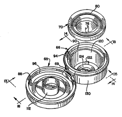
a novel, DLa~l-laLdized cartridge 64 (FIGS. 3, 5, And 12).
The cartridge 64 is adapted to be engaged with the
housing 50 and retained therein. The cartridge 64, as
illustrated in FIG. 12, has an ~c~ lQd, closed
conf iguration which is adapted to be received in the
housing 50. As illustrated in FIG. 11, the cartridge is
initially fabricated in an "open" condition and includes
a body 66 and a cover or retainer 68. In the preferred
_~; t illustrated, the body 66 and retainer 68 are
molded from a suitable th~ ctiC material as a
unitary L.u~LuLe with a hinge 69 ~YtQnrlin~ between, and
connecting, the body 66 and retainer 68.
In one presently contemplated ~ , the
body 66, retainer 68, and hinge 69 may be molded rrOm
polyethylene or polypropylene as a unitary ~LLU~;LUL~ in
the open conriguration Dub~LdrlLially as illustrated in
FIGS. 11, 13, 14, 15, 16, 17, and 18.
The cartridge 64 also includes a flexible,
resilient, slit-type ~l;spQncin~ valve 70 (FIG. 11) which
is mounted in the housing 66 and retained therein by the
retainer 68 when the cartridge is in the closed
configuration (FIG. 12).
The valve 70 is mounted at the passage 62
inwardly of the central deck 57 as illustrated in FIG.
3 . The valve 70 may be fabricated from th~ - ~e L ; n~
elastomeric materials such asl RilinnQ, natural rubber,
and the like. It is also c-,..L lated that the valve 70
may be fabricated from th~ ctic elastomers based
upon materials such as ~h~ ctic propylene,
ethylene, urethane, and styrene, inrl~ ;ng their
halogenated counterparts.
SUBSTITUTE StlEET ~RULE 26
W095/34500 2 1 884 ~ 9 r~ A'732
-- 10 --
As ill~ ed in FIGS. 6-8, the valve 70
includes a fl~Y~hl~, central wall 72 which has an
outwardly concave configuration and which defines at
least one, and preferably two, ~ p~ncin~ slits 76
extending through the central wall 72. A preferred form
of the valve has two, mutually perp~nrlic~ r,
1ntor~ecting slits 76 of equal length. The intersecting
61its 76 define four, generally pie sha~ed, flaps or
petals in the concave, central wall 72 which each open
outwardly from the intersection point in L~ se to
increasing ~ILe:S~-UL.~ of sufficient magnitude in the well-
known conventional manner.
The valve 70 includes a skirt 78 which extends
outwardly from the valve central wall 72. At the outer
(upper) end of the skirt 78 there is a thin, annular
flange 80 (FIGS. 6 and 7) which extends peripherally
from the skirt 78 in a downwardly angled orientation.
The thin flange 80 terminates in ~n enlarged, much
thicker, peripheral flange 82 which has a generally
dovetail shape transverse cross section.
The valve 70 is ~ pospd in the cartridge body
66 and is clamped therein by the retainer 68 which is
closed over the top of the valve 70 to form the fully
assembled cartridge as shown in FIGS. 5 and 12.
To i~ t.e the seating of the valve 70 in
the cartridge, the underside of the cartridge cover or
retainer 68 defines an annular, downwardly facing,
angled clamping surface 88 (FIGS. 5 and 11) for engaging
the top of the valve flange 82.
The bottom of the valve flange 82 is engaged
by an annular ~hm~ld~r in the body 66 which defines an
upwardly angled seating surface 90.
The spacing between the ' li ln J and seating
surfaces 88 and 90, respectively, in~.-as~s with
increasing radial distance from the center. Such a
SUBSrlTUrE SHEET (RULE 2~1
~ W095134S00 2 1 884 ~ S
-- 11
configuration defines a cavity with a LL~.n~væL e cross
section having a dovetail shape which generally conforms
to the shape of the valve flange 82.
This clamping aLL~l~. securely holds the
valve 70 in the cartridge body 40 without requiring
special internal support :.L~ .LuLæs or bearing members
adjacent the interior surface of the valve cylindrical
skirt 78. This permits the region adjacent the interior
surface of the valve skirt 78 to be substantially open,
free, and clear so as to r'~ te - ~. of the
valve skirt 78.
When the valve 70 is properly mounted within
the body 66 as illustrated in FIGS. 3 and 4, the valve
70 is recessed relative to an outer, top, peripheral
surface of the cartridge 64. This affords substantial
protection to the valve and generally reduces the
l ~kPl ihood that the valve will be inadvertently
contacted or damaged by eYternal ir.~LL, ~l ~ties when
the closure is opened but not ~1; QrPncinq product.
However, as P~l~inPfl in detail hereinafter, when the
product is ~;QP~need through the valve 70, the valve is
~i cpl aCP~ outwardly from the Lç:~_es~ed position. The
capability of the valve to be ii crl~-ed outwardly oPfers
certain advantages rli Ccl~Qapfl below.
The cartridge body 66 and retainer 68 have
exterior conf igurations permitting the retainer and body
to be held together in the cloQed conf iguration ( FIG .
12). In particular, the body 66 has an annular bead
rlPfininq a convex 5urface 94 (FIG. 18) extending
3 0 radially outwardly around the periphery of the upper
edge of the body. The retainer 68 defines an annular
groove 96 (FIGS. 5, 9, and 18) for receiving the body
bead 94 in a snap-fit er~7; when the retainer 68 is
closed over the installed valve 70.
SUBSTITUTE SHET (RULE ~6
wo ss/34soo 2 1 8 8 4 1 9 r~.,.).. . 1~ ~
-- 12 --
The cartridge 64 is adapted to be engaged with
the closure housing 50. To this end, the retainer 68
has an outwardly projecting, annular bead 98, and the
housing 50 defines an inwardly open, annular groove 100
(FIGS. 5 and 9) for receiving the cartridge retainer
bead 98 when the closed cartridge is ~ p~ed within the
housing in a snap-fit ~ yc~y adjacent the central
deck flange 57.
The cartridge 64 preferably includes a tear-
away, I ~ ident seal which ~nrl~ a pull tab 102
(FIGS. 2, 3, 12, 16, 17, 18, and 22) with an end grip
108. The pull tab 102 is defined around a central panel
104 (FIGS. 2, 3, 16, and 17). The central panel 104 has
a generally circular, disc-like configuration and i5
joined to the p~rirh~al portion of the retainer 68 with
a f rangible web of material designated in FIGS . 16 and
17 by the reference number 106. An inner portion o~ the
pull tab 102, for about a 180 arc length inwardly of
the pull tab 102, is connected via a frangible web 110
to the retainer central portion 104.
As illustrated in FIGS. 16 and 17, the
frangible web extends approximately 270 around the
outside edge of the pull tab 102. There is an
approximately 90 arc adjacent t_e outside edge of the
end grip portion 108 (FIG. 17) which is open so that
there is no connection between the grip portion 108 and
the outer periphery of the retainer 68. There is also
an opening at the end of the grip portion 108 and on the
inside radius of the grip portion 108. The grip portion
108 is thus not attached at its periphery to the
adjacent, but spaced-away, portions Or the retainer.
This allows the grip portion 108 to be grasped and
pulled upwardly.
The frangible webs 106 and 110 are preferably
defined by a reduced-~hirlrn~ portion of the material.
SUBSflTUTE SHEET [RULE 26)
~, wossl34soo 2 1 884 1 9 I~l/U~. /J~
-- 13 --
As illustrated in FIG. 22, the top surface and the
bottom surface of the retainer 68 may be provided with
grooves or notches for d.efin1n~ the Le~lu..:ed thirkn~cc
frangible web regions 106 and 110.
In order to open the seal, the grip portion
108 i5 grasped between the thumb and index finger, and
the grip portion 108 is then pulled outwardly. The
central portion 104 pulls away from the center o$ the
retainer 68 as the frangible webs 110 and 106 are torn.
When the central portion 104 is completely torn away,
the valve 70 is exposed as illustrated in FIG. 4.
When the closure 40 is in the closed
configuration, before the central portion 104 is torn
away, it is desirable to provide a valve restraint
member to prevent actuation or opening of the valve.
When the container is not being used to ,1; cpPn~e
product, the container could be inadvertently subjected
to external forces (such as impact forces during
n~ll inq or shipping~, and these forces could increase
the internal ~L-:SDULa in the container. q'his could
cause the valve to open. To eliminate this potential
problem, an annular restraint wall 112 (FIGS. 5, 9 and
18 ) is provided on the inside o~ the retainer central
portion 104 adj acent the valve central wall 72 . This
pL~Ve~ S the valve central wall 72 from moving or
~rticulating suf~iciPn~ly outwardly to open the
dispensing slits 76.
Preferably, the cartridge 64 also includes an
inwardly extending wall 120 (FIGS. 3, 5, 9, 16, 17, and
- 30 18). Projecting radially inwardly from the distal end
of the wall 120 are four arms 122 (FIGS. 16 and 17)
which support a centrally ~ p~P~ baffle plate 124.
The cartridge 64 also includes an outer seal
wall 130 (FIGS. 3, 5, 9, 10, 11, 13, 14, 15, 16, 17, and
18). As illustrated in FIG. 5, the P~Prior surface of
SUBSriTUTE S~IEET (RULE 26)
W0 9s/34~00 2 1 8 8 4 1 ~ r~
-- 14 --
the seal wall 130 is received within the ~nntA;n~r neck
44 and seals against the cylindrical interior surface of
the neck 44. Preferably, at lea6t a distal annular
portion of the seal wall 130 is _ t resilient so as
to provide a leak-tight seal between the cartridge and
the container neck.
The product within the container 42 can be
~iRp-.nco~ from the cnntAin~r by S~l~2in~ the container
sufriciently to force the product through the valve 70.
Typically, this is effected by first inverting or
tilting the container 42 so that the valve 70 is
oriented to discharge generally downwardly. Typically,
the liquid within the container rlows downwardly, under
the influence of gravity, and fills the container neck
region. The liquid flows past the baffle 124 and
against the inside of the valve central wall 72. The
valve 70 is preferably designed so that the weight of
the liguid will not deflect the valve downwardly under
normal, static conditions. The valve will thus be
spaced away from the annular restraint wall 112 as shown
in FIG. 5 (except that the container would be inverted).
However, if the internal ~lc:s:,uLa within the
container is in~ ased temporarily (as shown in FIG. 9),
then the increased p~l:S~ULe: (which could also include
the weight of the liquid within the container i~ the
container was inverted) could deflect the valve central
wall 72 downwardly against the distal end of the
outwardly projecting annular restraint member 112. This
might occur, for example, if the external ~ sc,u.~= were
suddenly reduced (e.g., during LLO~ UULL in an airplane,
or if the container were subjected to an external impact
rorce). The annular restraint wall 112 prevents the
valve 70 from moving sufficiently outwardly to open the
~licr~-ncin~ slits 76 under such conditions.
SUBSTIJUTE SHEET ~RULE 26)
~ wossl34soo 2 1 884 ~ 9 i~
-- 15 --
If the closure i5 ~ s~lu~ Lly opened by
tearing away the pull tab 102 and central portion 104,
then an increase in the internal ~ s~uLe in the
container, as by sg~ 7s;nq the container, will cause the
valve to open as illustrated in FIG. 10. When the valve
is subjected to an increased container ~Les,~ULel the
valve central wall 72 is d ~ Cpl AI~Q-l outwardly while still
maintaining its generally concave configuration. The
outward diCpl;ll~ ' of the concave, central wall 72 is
0 A ' Led by the relatively thin, flexible, skirt 78.
The skirt 78 moves from a rest position (FIG. 5) to the
pressurized position (FIG. 10) wherein the skirt is
projecting outwardly through, and beyond, the ll;cpPnci
opening .
The valve 70 does not open (i.e., the slits 76
do not open) until the valve central wall 72 has moved
subst~n~iAlly all the way to the outermost position.
Indeed, as the valve central wall 72 moves outwardly,
the central wall 72 is subjected to radially inwardly
directed e~Dion forces which tend to further resist
opening of the slits 76. Further, the central wall 72
generally retains its outwardly concave configuration as
it moves forward and even after it reaches the outermost
position (FIG. 10) . If the 1ntC~rnA1 PL~ ULe is
5~lffi~ ntly great, then the slits 76 begin to open to
~i cp ~nce product as diagL tically illustrated in FIG.
10 .
Because the valve central wall 72 is located
at its outermost position when ~;cp~n~in~ product, the
dieroncin~ process can be more easily obseL~ed by the
user. Further, because the valve .l~er~nc~c product when
it is in the outermost position and not in the L~_eased
position (FIG. 5), the valve can be more easily directed
to d ~ cp~nce the product at a selected target site.
SUBSrIT~ `T (RULE 26)
wo gs/34soo 2 1 8 8 4 1 9 r~ 732
-- 16 --
It will be appreciated that the baffle plate
124 functions to mlnimi~e undesirable impacts on the
inside of the valve 70, as when the container is being
squ~zQd excessively hard or shaken. The baffle plate
124 also functions in this manner even when the closure
is sealed closed with the annular restraint member 112
in place.
Further, it will be appreciated that when the
annular restraint member 112 is in place, and when
pL-~s~uL.2 trAnci~ntC force the valve 70 against the
restraint member 112, the restraint member also
functions, in addition to preventing excessive - ~, L
of the valve 70 toward the open position, as a seal on
the outer surface of the valve central wall 72. Thus,
should a small quantity of liguid leak through the valve
slits during a transient over~ u~ ~ condition, the
sealing _ ,_; L illustrated in FIG. 9 will at least
initially contain the leaking product on the inside of
the annular restraint member 112.
A variety of dit'ferent sizes and shapes of
containers can be readily provided with a closure 40
having a standardized cartridge 64. The cartridge,
ln(~ in~ the valve 70, can be provided in one,
universal design having a standard shape and standard
dimensions. The inside of the closure housing 50 can be
provided with a receiving region of a ,,k.l.~ar 1 shape and
6ize for the standard cartridge 64. Thus, only the
housing skirt 51 need be changed as n~ C6:~ry to
~ 'qte a container neck having a particular size
3 0 and shape .
Further, the use of a standard cartridge with
a standard valve permits the use of a single
manufacturing process to assemble the valve in the
cartridge. The cartridge can thereafter be readily
handled at a high rate of speed by automatic ~~~-h;n~ry
SU3STITUTE SHEET tRULE 26~
-
WO 9!i/34S00 2 1 8 8 4 ~ 9 L ~
-- 17 --
which installs the cartridge in the closure housing.
This eliminates the need for directly h;ln~l in~ a small,
fleYible valve during installation in a larger closure
housing .
The use of a unitary cartridge, which in~ c,c
the unitary body, hinge, and retainer, minimi~s the
number of separate parts that must be handled. Further,
the snap-~r ;~, of the cartridge retainer with the
cartridge body over the body f lange permits a relatively
rapid and efficient assembly process for capturing the
valve. SllhTeq~l~ntly~ the snap-fit el~yay. L of the
cartridge in the closure housing a~ ' Les relatively
high speed pro~l~r~ n with a minimum product reject
rate .
Further, the use of a separate cartridge
easily ~ tes the creation of a multi-color
closure. The cartridge can be fabricated in one color,
and the closure housing can be molded in another color.
If desired, the tear-away tab 102 and central
portion 104 may be completely eliminated. In such a
case, the closure would have the appearance as shown in
FIG. 4, and the valve 70 would be exposed at all times.
Alternatively, the central opening in the
cartridge as illustrated in FIG. 4 -- which provides
access to the valve 70 -- could be covered with any
other suitable seal. For example, FIG. 23 illustrates
the use of a flexible, disk-like seal 140 which is
adhesively attaohed to the ~lat, exterior, end surface
of the retainer 68.
Another form of a closure inco.y-lraLing ~he
principles of the present invention is illustrated in
FIGS. 24 and 25. A closure 142 has a generally
rectangular configuration and is ~i~ros~l on the top of
a container 144.
SU8S~1TUT~ SI~EET ~RULE 26~
Wo95i34500 ~ 1 8 84 1 9 ~ . 5~-732
-- 18 --
The container 144 has a neck 146. The neck
146 i8 covered on two opprcin~ sides and at the rear by
a shroud 148.
The closure 142 inrl-~Aoc a deck 150 with a
downwardly AQpQnA;n~ front wall 152. The deck 150
defines an opening 154, and a collar 156 depends
d~ lly from the underside of the deck 150 around the
rnntA;nPr neck 146. The distal end of the closure
collar 156 includeE~ an inwardly projecting bead 158 for
Qn~;n~ an outwardly projecting bead 160 on the
container neck 146.
A cartridge 164 is mounted within the closure
collar 156 at the top of the container neck 146. The
closure 164 ; nrl ~Aoq a body 166 and a retainer 168
engaged around a valve 170. The cartridge body 166,
retainer 168, and valve 170 may be iul~r Lal.Lially
identical to the body 66, retainer 68, and valve 70
described above with reference to the first Qmho~
of the cartridge 64 illustrateq in PIGS. 1-2Z.
The cartridge 164 is retained via a friction-
fit or snap-fit el,yily. L with the inside surface of
the closure housing collar 156. The closure housing
deck 150 extends directly over the peripheral portion of
the retainer 168. The cartridge 164 does not include
the pull tab 102 and central portion 104 employed in the
cartridge 64 described above with reference to the
cartridge 64 illustrated in FIGS. 1-22. Instead, the
closure has a hinged lid 171 with a downwardly
projecting, annular, restraint member 173. When the lid
171 is closed tin the position ill~ L~--ed in FIG. 24),
the annular restraint member 173 is positioned relative
to the valve 170 in a manner similar to the positioning
of the first ~ restraint member 112 relative to
the valve 70 as described above with reference to FIGS.
1-22.
BS~ITVTE SlfEET (RVLE 26)
WO95/34S00 2 1 8 84 1 q l~ 5 J.~.C
-- 19 --
FIGS. 26-28 illustrate another ` i of a
closure 240 il~.U~IJuLating the print~rlps of the present
invention. As shown in FIG. 28, a closure is adapted to
be mounted on the neck 244 ûf a container 242. The
cr~nt~;nPr neck 244 has threads 256, and the closure 240
has threads 255 for Pn~ i n~ the container neck threads.
The closure neck threads 255 are defined in a
housing 250 which receives a cartridge 64. The
cartridge 64 i8 identical to the cartridge 64 described
above with reference to the first: ` ~'i- L of the
closure illustrated in FIGS. 1-22- The relati~ nqhir of
the cartridge 64 with the housing 250 is somewhat
different in the closure 240 compared with the
relationship of the cartridge 64 with the housing 50 in
the closure 40 illustrated in FIGS. 1-22. In
particular, the closure 240 has a maximum diameter which
is greater than the cartridge 64 for c-n~7in~ ~ larger
rli: ' or neck 244 of the ~ontAinPr 242. As a
~ ~"CP~lU ~,~e~ the inside cylindrical surface of the
container neck 244 is not engaged by the cartridge
collar 130. This is in contrast with the first
` -';- t closure cartridge wherein the collar 130
engages the inside, cylindrical surface of the ContlinPr
neck 44 as shown in FIGS. 5, , and 10. Instead, as
~hown in FIG. 28, the housing 250 has a ~ Ldly
projecting, flPyihl~p seal member 259 which engages the
top, annular surface of the rnnt~inPr neck 244 to
provide a seal.
It will be appreciated by comparing FIG. 28
with FIG. 5 that a standardized cartridge 64 may be
employed in h-'l'cin~C having different diameters (~nd
different container ~-yag configurations). Indeed,
another P~ho~i- L of a closure, with still a different
container Pn~a, L configuration, is illustrated in
SUBSTITUTE Sl I~ET ~RULE 26j
WO 95/34500 1 ~
21 8841 9
-- 20 --
FIGS. 29 and 30 wherein the closure i8 generally
designated by the reference number 340.
The closure 340 ; nr~ S a hou6ing 350 having
an outer, cylindrical wall 351 and an inner, cylindrical
wall 353. The inside surface of the cylindrical wall
353 defines a thread 355 for ~n~a7in~ a mating thread on
the neck of a container (not shown~.
The housing 350 also derines a Le c~:ssed deck
357 d~fin;nq an opening 362 afrording ~ ;~tion
between the container l~nd the exterior of the housing.
Projecting upwardly rrom the deck 357 is a collar 359.
The collar 359 i5 a generally cylindrical wall d
r~dially outwardly of the opening 362.
The housing 350 receives a cartridge 64
id~ntir~l to the cartridge 64 described above with
reference to the first; ~'; ~ of the closure
illustrated in FIGS. 1-22. The cartridge 64 includes
the abv~ desvLibed, ,' .lly d~pen~;n~ collar 130,
and the outside surface of the collar 130 Sc, 11 ;n~ly
engages the inside surface of the closure collar 359 to
establish a seal. Another seal is est~hl; ':h~'i between
the bottom Or the closure deck 357 and the top of the
container neck with a rlexible annular seal member 359
which extends ~ dly rrOm the deck 357 as shown in
FIG. 30.
The cartridge 64 can be - ~if~d according to
the prinrirl~c Or the present invention, and FIG. 31
illustrates such a modification wherein the --';fied
cartridge is designated generally by the reference
number 464. The cartridge 464 ;nrl~ C a body 466
molded in a unitary ~.VllaLL l~;~iOn with a retainer 468
which is c~nn~-rte~l to the body 466 with a flexible strap
or hinge 469. The retainer 468 has a ring-like
configuration defining a central opening 471. A valve
470 is retained in the body 466 by the retainer 469
9UBSrITUTE SHEET IRULE 26)
_
~ W095134500 2188419
-- 21 --
which is snap-fit into a groove 467 in the body 466.
The valve 470 may be identical or substantially
identical to the valve 70 described above with ~:f~L..,~e
to the ~ illustrated in FIGS. 1-22.
In one contemplated i L, the opening
471 in the retainer 468 is not covered with a seal, such
as the pull tab 102 and central portion cover 104
described above with reference to the: 'i- L
illustrated in FIGS. 1-22. Thus, the cartridge 464
illustrated in FIG. 31 may be used immediately to
~qi cpPnCe the product from the container through the
valve 470 without having to remove a seal ~LU~LULe: or
other closure _ ^nt.
The cartridge body 466 defines a bead 473
which extends at least part way around the periphery of
the body 466 for engaging a mating groove in a closure
housing so as to effect the ing of the cartridge
464 in such a closure housing. The bead 473 is thus
fllnrti~n~lly analogous to the bead 98 on the firs~
~ of the cartridge 64 which is received in the
housing groove 100 as illustrated in FIG. 5. However,
it will be appreciated that in the : ' i of the
cartridge 464 illu:,~L-ILed in FIG. 31, the cartridge bead
473 is defined by the body 466, and not by the retainer.
This is in contrast with the cartridge 64 illu2.~Lc.ted in
FIG . 5 wherein the bead is def ined on the retainer 68 .
The cartridge 464 illustrated in FIG. 31 may
be modified. For example, the top o~ the body 466 may
be covered with an adhesively secured, removable sealing
30 member 481 as illustrated in dotted lines in FIG. 31.
Such a removable sealing member 481 would serve a
function analogous to that of the removable member 140
described above with reference to the: ' ~i t
illustrated in FIG. 23. In particular, the member 481
would provide an additional barrier between the
Sll~STITUTiE SHEET ~RVLE 26)
_ _ _ _ _ _ _ _ _ _ _ _ , . . . _ . . _ _ .. . . _
WO 95/34500 1 ~
2188419
-- 22 --
container contents and the exterior of the closure. The
member 481 could also serve as a I -_vident feature.
The cartridge 464 may be modif ied in other
ways also. For example, the cartridge 464 may be
provided with exterior threads 487 as illustrated in
dotted lines in FIG. 31. Such threads could be employed
with a special container having an internally thL~,aded
neck for securing the cartridge directly to the
rnnt~in~r. The cartridge 464, as thus ~ fied~ would,
in effect, become a lete closure for the container.
Further, the cartridge 464 could be provided
with an additional, outer cylindrical wall (not
illustrated~ that is spaced beyond, and is cl ,~cw~ l ~ic
with, the cylindrical wall of the body 466 illustrated
in FIG. 31. The inner surface of such an additional,
outer wall could be provided with an internal thread for
engaging a conventional exterior thread on the neck of a
conventional ,-lnt-~inPr. Such a modified cartridge would
also become, in effect, a complete closure for the
2 0 container .
Further, it will also be appreciated that a
closure may be provided with a cartridge, such as the
cartridge 64 ill~ Lc.Led in FIGS. 1-22, wherein the body
66 and ret~iner 68 are not molded together as a unitary
piece. In such a ~ tr~tion, the hinge 69 (FIG. 16)
would be eliminated, but the other fea~uL~s of the
cartridge would be retained 50 as to still provide a
novel, ~ aLdized, self-contained cartridge for
mounting in a housing of a closure . Such a h i ng~ 5
3 0 cartridge may or may not include a seal member, such as
the seal member 140 illustrated in FIG. 23 or such as
the pull tab 102 and central portion 104 illustrated in
FIG. 2.
It will be readily observed from the foregoing
detailed description of the invention and from the
SUBSTITUTE S~I~ET (RULE 26~
~ WO 95/3450~ 2 1 8 8 4 1 q ~ ,32
-- 23 --
illustrations thereof that ~us other variations and
~ 'ifi~ations may be ~ffect~ without departing from the
true spirit and scope of the novel Co~ Ls or
prinripl~q of this invention.
~U~SriTUI~ SHEET IRU~E 7fi)