Note: Descriptions are shown in the official language in which they were submitted.
Wo 96/26320 2 1 Q~ ~ 4 5 ~ Pcr/uss6/02487
."~
IMPlROVEMENT IN AUTOMATED, LASER
ALIGNED LEVELING ~PPARATUS
I~ACKGROUND OF T~IE INVENTION
Field of the Invention
TlliS invention relates to apparatus for leveling flowable materials such
as concrete, aspllalt, dirt and gravel in wllich an elongated leveling member ismaintained in alignment witll a desire~ leveling plane by a laser alignment syslem. In
5 particular, it relates to an improvement in such a system having a pair of laser bealn
de~ectors on opposite ends of the elongated leveling ,-,el"l~er so tllat the Sys~clll can
mailltain leveling accuracy when one of the detectors is temporarily blockcd from
receiving the laser beam such as by a support column, a truck, personnel or o~her
obstruction.
Background Infomlation
The invention has particular application to concrete screeds, hul llas
application to other apparatus for leveling flowable materials such as, for installcc
graders.
The concrete screed is a device used when pouring and leveling (i e.,
screeding) large concrete floors, sucll as used in large warehouse buildings, departlncllt
stores and other large area constmction projects as well as large outdoor COllClr~C
alcas. ~xalnplcs ul cullcretc scleeds are provided ill U.S. patetlt llulnbers 4,()S5.
and 4,930,935. These machines consist of a self propelled, rotating turret supponin~
a large telescoping or extendal le boom, which can typically extend 20 feet fronl lhe
turret. At the end of the boom is a self adjusting screed head, typically about 13 rcc~
wi(le whicll can automatically nlailltain a level r~osition regardless of the macllillc s
wo 96/26320 ~ 2 ~ 5 ~ PCr/uss6lo2487
- 2 -
position. During tlle pourhlg of a large concrete floor, trucks deliver Ille concrete and
discharge it on the ground. The screed head is positioned at the hea(l of the freshly
discharged concrete at exactly the desired horizontal height. The screed head is then
snlootllly pulled toward tlle tur-et by the boom, tllereby evenly leveling and
consolidatillg the concrete at exactly the desired horizontal lleight. The screed head is
then repositioned to an adjacent location where fresh concrete has been placed by a
truck. Agahl, the screed head is retracted toward the turret creatillg another section
of smooth, (screeded) concrete.
One of the inlporta:lt features of these prior art concrete screeds is that
they produce an e~tremely flat, level concrete floor in a short time-period. Each of
the individually screeded sections matclles the height of the adjacent sections witl
precision. In order to accomplish this, an automatic laser alignment systeln is
provided. A laser projector is first installed outside the l)cli,neler of the area to be
poured. The laser projector generates a beam which is swept in a horizontal plane to
provide an extremely flat leveling plane, nonnally several feet above the ground.
Sensors responsive to the laser beam are located on posts at both ends of the moveable
screed head. These sensors monitor lhe beam location relative to the end posts an(l
or below tlle desired location on the end posts. ~ertical actuators, such as hy(lr;llllic
2() cylinders, are provi~Jed ror bolh ends of the screed head. These venical actua~ors
allow each end of the screed head to be vertically moved so that the respective ends
are kept within a very small tolerance of a desired vertical position as the scree(i llc~d
pulls the concrete toward the turret. A controller provides automatic control o f the
screed end positions, and therefore, screed lleight and levelness, during the pullin~ of
the concrete. For example, if the controller detects that the laser beam is mo~in~
down on a screed end sensor it provides signals to the actuator (such as to solenoi(3
valves for the hydraulic cylinder) for that end to move the screed end down un~il tllc
beam is centered again Oll the sensor. As the screed is moved from posi~ion to
position, the screed head always reestablishes and m~in~ins the correct vcnical
location of bo~h en(ls by means of the laser alignment system.
The commercial embodimellt of the concrete screed described hl tlle
above patellts is kno-vn as (he LASER SCREED (trademark Somero Enterpriscs. 1~
The LASER SCREED incorporates a feature which provides frequent ~onlrol
wo 96/26320 2 1 8 8 4 5 6 PCrrUSs6/02487
,~"~
corrections for the screed end heigllt. Tlle ~elf-propelled frame has stabilizer legs by
wllicll it can be tilted so lhat the boonl retracts alollg an upward 2% grade (i.e., ~he
boom is angled upwar(Js from its free end to the turret). ~.s tlle boom end is pulled
toward the turret, it is gradually rising in elevation. Ho-1~ever, the laser sensors on tlle
screed head ends are rapidly and contirlually sensing the height of the screed end posts.
When the screed end post height increases by the very small margins pennitted by the
maclline (i.e., 1/~" hlcrease), the laser sellsors send a signal to the central processing
unit to adjust the screed end post height back down to the desired elevatiom In this
manner, each side of the screed head is independently and automatically controlled lo
stay within a very narrow elevation tolerance band. This provides for a practically
seamless control of concrete lleight betw~n adjzcent sections tllat are pulled, plus
providing a very flat, level surface within the pulled section. The operator merely has
to command the screed boom to be retracted and the concrete is automatically screeded
to the correct height, blending with a height of adjacent concrete scctions.
While Ihe laser screed works very well, there is one problem which has
remained unsolved during the eight (8) years since the introduction of tlle LASER
SCREED. The laser sensors can only function if they have an unobstmcted vicw of
an alignment source. If the laser beam is broken by an object, SllCh as a building
vertical support column, then the sensor will not provide a signal to tlle controller. and
the affected screed end will not automatically adjust its height. Unfortunately. IllOSt
building sites have a dozen or even several dozen, vertical support columns wh iCIl are
in place when the concrete floor is poured. As the screed is moved around the flo~-r.
pulling the numerous section of concrete, the vertical suppOn columns frequently l-lock
îhe laser beam from llittillg the sensors during part of each pull. This interfercncc is
called "column block" and it dismpts the automatic operation of the laser screcd.
Witllout a control signal, the controller unit does not know how to adjust the scrccd
end. Therefore, an hlstrument light is provided to inform the operator that thcre is
column block on the affected sensor. The operator must immediately assume mallual
height control of the affected screed end when the column block light is illunlhl;l~e(l.
The boom continues to pull toward the turret at its set speed. Because of the 2'7o
upward grade established for the boom, the lleight of the screed end must somehow l-e
adjusted to prevcnt the screed end from also rising at the 2% grade and ~llererore
ruining the floor flatness. The operator must manually control the scree(l end hei~llt
wo 96126320 2 1 8 8 4 5 6 PCr/USs6/02487
-- 4 -
and esthnate tlle correct heigllt corrections as the ~oom is retracted ulltil the sensor
moves into a position where it is unblocked. At this pohlt, the autonlatic system
becomes active agaim Unless the manual correcticins were made reasonably accurately,
the screed end is abruptly moved to its correct heigllt. This corrective movement can
cause an unwallted wave or disruption in tlle floor surface. It should be noted that
while the boom is retracting, the operator is o~ter roLating the turret right or left hl
response to obstacles (such as the vertical columns) and is checking around the macllille
to make sure that none of the numerous l,el~ol~nel or their equipment are getting too
close to lhe machine. It is therefore very undesirable to also require the operator to
continually mollitor whetller column block exists. In spite of these unwanted
characteristics, tllere has been no solution to the problem of "column block" up to this
point. It has also been found that in some jobs, "column block" is more frequently
caused by the tnlcks delivering the concrete and other equipment rather than thevertical COIUIllllS. Thus, this provides even more incentive to find a solution to the
problem.
There is a need, therefore, for an improved laser aligned apparatus for
leveling llowable materials, and in particular for concrete screeds.
There is a specific need for such improved apparatus WlliCIl can maintai
floor levelness when one of tlle sensors becomes blinded by an obstmction.
There is an additional need for such improved apparatus which responds
automatically to blinding of one of the laser detectors.
Sl~ RY OF TI-IE INVENTlON
These needs and others are satisfied by the invention which is clirecte
to apparatus for leveling flowable material having a control device which, wllcll olle
radiant energy beam sensor is blocked by an obstruction from receiving the projected
beam of radiant energy and therefore does not generate a signal indicating an elevatioll
deviation, sends tlle detector signal from the unblocked sensor to the adjustment
mecllanisms at botll ends of the elongated leveling member until the blocked scnsor
clears the obstruction an-l again begins to generate elevation deviation signals.
In one embodimenl of the invention, switching control means is hlscrte
bet~veen the controller which generates the adjustment signals, such as for sol~noi~
valves for hydraulic actuators adjusting the elevation of the ends of the ek~llg;llc-l
leveling member, and the solenoid valves. In this embodiment, the s~itching conlrol
wo 96/26320 2 ~ J 6 Pcrluss6lo2487
mealls, whicll includes a processor such as a programmable logic controller (PLC), has
a timer wllicll repetitively limes an in~ecval longer th~n the dur2tion between adjllstlnellt
signals when the elongated leveling device is moved along a boom included at a
predetermined angle to the projected l~ve'in~ plane. Absence Gf an adjustment signal
during this interval is an indication that tlle associated detector is biinded, and initiates
application of the adjustment signal from the unblillded side to the solenoid valves on
both sides. When an adjustment signal is again received from tlle detector that was
blinded, indicating that it has cleared the obstruction, the respective adjustmellt signals
are sent to the associated adjustment mechanisms (i.e., solenoid valves)
In anotller embodiment of the invention, the intelligent switcll is placed
bc~weell the sensors and the controllers which generate tlle adjustment signals. As the
sensors continuously send signals to the controllers which indicate the position of the
sensor relative to the projected leveling plane, the switching means can hnme~liately
(letect that a sensor has been blocked from receiving the radiant energy beam, such as
by an obstruction. Thus, the switching means immediately applies tlle signal rrom the
ullblocked sensor to both inputs to the controUer means for generating both adjustment
signals.
I~RIEF DESCRlPrION OF TI-IE DR~WINGS
A full understanding of the invention cari be gained from tlle following
description of the preferred embodiments when read in conjunction wilh tlle
accompanying drawings in wllicll:
Figure l is a partially schematic side elevation view of leveling apparatus
incorporatillg the invention.
Figure 2 is a schematic laser leveling control system for tl~e ~ ralus
of Figure 1.
Figure 3 is a schematic diagram illustrating in more detail a porlion of
the control system of Figure 2.
Figure 4 is a logic flow chart for the control system of Figllre 2.
Figure 5 is a schematic diagram of an alternate control systcm in
accordallce with the invention.
I)ESCRIP'rION OF TIIE ~REFERRE;D EMBODI~IENT
The invention will be described as applied to a laser aligned c- ncrele
screed; llowever, it will be realized by those skilled in the art tllat the invclllioll is
~lw
- 6 -
application to other apparatus for leveling flowable materials such as for instance
graders.
The concrete screed 1 is oF the type disclosed in U.S. patent number
5 4,655,633, and in particular that described in U.S. patent number 4,920,935. The
concrete screed 1 includes a self-propelled frame 3 mounted on steerable wheels 5.
Mounted on the frame 3 is a rotatable turret 7 which supports a cantilevered,
telescoping boom 9. Mounted on the free end of the boom 9 is a screed assembly 11,
the details of which can be understood by reference to patent number 4,930,935. The
10 frame 9, has front and rear stabilizer legs lOa and lOb which can be separately
adjusted to position the boom 9 at an angle cY relative to the horizontal using a level
gauge (not shown). Preferably, the angle ~x is set to establish about a 2% upward
grade for the boom.
The screed assembly 11 includes a horizontal support member 13
15 secured at its center to the end of the boom 9. An elongated leveling member in the
form of screed 15 having a longitudinal axis 16 is suspended at one end 17 from the
horizontal support 13 by a screed elevation tube 19 and at the other end 21 by the
elevation tube 23. The elevation tubes 19 and 23 respectively form part of elevation
adjustment mech~ni~m~ 25 and 27.
The elevation adjustment mechanism 25 includes a guide tube 29
secured to the one end 17 of the horizontal support 13 and in which the elevation tube
19 is vertically slidable. A double acting hydraulic cylinder 31 is mounted at its lower
end to the guide tube or horizontal support 13 and has its actuator rod 33 connected
to the upper end of the elevation tube 19 so that operation of the hydraulic actuator 31
25 raises and lowers the elevation tube 19, and therefore, adjusts the elevation of the end
17 of the screed 15 relative to the horizontal support 13. Similarly, the elevation
adjustment mechanism 27 includes the guide tube 35 in which the elevation tube 23 is
vertically positioned by the hydraulic actuator 37 having its actuator rod 39 connected
to the upper end of the elevation tube 23.
The hydraulic actuators 31 and 37 are operated by solenoid valves
41 and 43, respectively, which control the flow of hydraulic fluid provided by a pump
45 through hydraulic lines 47. The solenoid valves 41 and 43 are controlled by
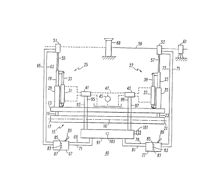
adjustment signals provided by a laser alignment system 49. The alignment system 49
includes a pair of spaced apart laser beam detectors 51 and 53 supported by masts or
~'
Wo96/26320 21 8~456 Pcr/uss6lo2487
posts 55 and 57 nlounted on top of the elevation tubes 19 and 23 at the first atld second
ends 17 and 21, respectively, of the screed assembly 11. These laser beam detectors
51 and 53 may be, for installce, of the type sold under Model No. R2S or R2~ by
Spectrat-Pllysics L~serplane, Inc. Constructior, and Agricult.,ral Division o~ Dayton,
S Ohio. These receivers are 360~ OMNI-directional receivers which detect the position
of a projected leveling plane 59 generated by a laser bealn frotr~ a laser beacon
projector 61. The projector can be of the type sold under model numbers ELI, 1()44-L
or 945 also by Spectra-Physics Construction and Agricultural Division of Dayton,Ohio. The laser projector 61 is positioned off to the side of the area where concrete
is to be screeded. The laser beam detectors 51 and 53 generate a pair of signals WhiCIl
provide an indicalion of the elevation of the respective detectors relative to the
projected leveling plane 59. The two signals generated by the laser detector 51 are
transmitted over leads 63 and 65 to a controller unit 67. This controller may be of the
type sold under Model No. CB20T0 also by Spectra-Physics. The detector 51
generates a steady higll level logic signal on the lead 63 if the detector 51 is low
relative to the projected leveling plane 59. Under these conditions a pulse signal is
routed on the lead 65. If the detector 51 is high relative to the projected ieveling r~lane
l~resent on the lead 63. Wllen the elevation of the detector 51 is in alignlllcnt wi~h lllc
2() cl~v~tioll of tllc r~rojcctc(l levcling l~lallc 59, ~ stca(ly higll lcvcl l~gic 'iigl~;ll is
generated on both leads 63 and 65. If the detector 51 does not detect the refcrence
laser beam, as when the beam is blocked by an obstruction such as the support collJrnn
68, the pulse signal is generated on both leads 63 and 65.
The controller unit 67 generates first adjustment signals on the lca(ls 69
and 71 in lesponse to the signals received on the leads 63 and 65. In the systems of
patent numbers 4,655,633 and 4,930,935, these adjustment signals were ap~llicd
directly to the solenoid valve 41 to raise or lower the first end 17 of the laser screcd
to bring tlle detector 51 into alignment with tlle projected leveling plane 59. The laser
detector 53 generates similar signals on leads 73 and 75 whicll are utilized by the
controller unit 77 to generate second adjustment signals on the leads 79 and 81 for
operation of the solenoid valve 43.
Tl1e controller UllitS 67 and 77 are each provided wi~ll three hl(lic.llur
lights: a center green light 83 indicating that the respective detector 51 or 53 is
wo 96/26320 2 1 ~ P, 4 5 ~ PCr/uss6/02487
vertically aligne(3 with the projected levelillg plane 59; an upper oran~e ligh~ 85
indicating that llle detector is above lhe projected leveling plane 59; all(l a secon(l lower
orange light 87 indicating that tlle detector is below the projected levelhlg plalle.
Under nonnlal circumstances, the systenl automatically maintains both ends of tlle
screed 15 at proper elevation relative to the projected leveling plane 59, and tlle ligllts
provide the operator witll an indication lhat tlle automatic system is accomplishing this
task. However, wl1ell one of the detectors becomes blocked from receiving the
projected laser beams such as by tlle column 68, a truck or other equipment, or even
a worker, the automatic system can no longer adjust th~ elevation of the end of the
screed assembly 11 having the blocked detector. According to the present state of tl1e
art, the operator must take over and operate a hand control 8g to provide inp~lts to llle
blocked side. As discussed above, tllis is not completely satisfactory, as the operator
does not have precise infonnation on tlle elevation of tlle affected end of the screed.
This can cause unevenness in the floor, especially at the point wllere the detector
becomes unblocked and makes what may be a gross correction to brhlg the associated
end of tlle screed back into proper alignment.
As was discussed abov~, tlle boom 9 on which the screed as.scn~l-iy 11
is carried, is supported at an angle ~ which produces about a 2~ upward ~ra~e
relative to the horizontal, and tl1erefore, to llle projected leveling plane 59. Thus, as
the screed assembly 11 is pulled toward the frame 3, the screed 15 rises. This rc~nircs
periodic adjustment downward of the elevation tubes 19 and 23 to maintain a Icvel
floor. Thus, first and second adjustment signals are regularly generated l~y ~lle
controller units 67 and 77. In accordance with the embodiment of the in~clllion
illustrated in Figure 2, a switching control 91 is interpo~ed in the lines 69, 71 al~l 79~
81 between the controller units 67 and 77 and the solenoid valves 41 an(l 43. Tllc
switching control 91 monitors the adjustment signals generated by the controller unils
67 and 77. With the screed assembly 11 being tr~nclated by the boom 9 at a consta~lt
rate, the adjustment signals should be generated at specified intervals as tlle scrce(~
assembly is raised by the angled boom 9. If the switching unit 91 does not dc~cct Illc
adjustment signals from a controller unit 67 or 77 for this specified inter~al idetennines that the associated detector 51 or 53 is blocked. Under tllese con(Ji~iolls~
the switching control 91 switches the adjustment signals from the con~rollcr ~nlit
associated with the unblocked dctector to the solenoid valve associated with ~llc l~lcck
W096/26320 2 ' 8~4S6 Pcr/uss6l02487
.,~"",_
detector so that bolh of the solenoid valves then receive tlle adjustmellt signal generated
from the unblocked detector.
Whell the switcllillg control 91 again detects adjustlnellt signals fronl the
controller Ullit associated with the fonnally blocked detector, indicating that that
detector is now seeing the laser beam, the respective adjushlleilt signals are again
directed to the associated solenoid valves. Thus, in the example shown in Figure 2,
where the detector 51 becomes blocked by the column 68 so that adjustment signals are
no longer generated on the leads 69 and 71 by the controller unit 67, the switchhlg
control 91 applies the adjustment signals generated on the leads 79 and 81 by tlle other
controller unit 77 to tlle solenoid valve 41 over the leads 93 and 95, as wel~ as, scnding
those signals over to leads 97 an(l 49 to the associate~ solenoid valve 43. If the
switchillg controller 91 detects that both of the detectors are blocked it sounds an
audible alann 101 and blilLlcs a light 103 to in~licate this condition to tlle operator
Obviously, manllal control must be applied until at least one detector l~ecomes
unblocked.
E;igure 3 is a schematic diagram of the switching control 91. Tlle
switching control 91 includes 2 two-pole, double throw, relay switches 105 an(J 1()7.
Operation of the relays is controlled by a processor in the fo~n of a prograllllllal~le
logic controller (PLC) 109. The PLC 109 monitors the signals O.l the leads 69. 71,
79 and 81, and when it detects the absence of adjustment signals on one of Ihe pairs
of these leads, it ene,gi~es the coil of the al)~,o~.iate relay 105 or 107 to transfer the
signals on the other pair of lines to the affected lines. The switches 105 an(l 1()7 are
shown in their norrnal, unene.~i~ed states which prevails when both of lhe laserdetectors are receiving the laser beam. Under tllese conditions, the signals On le;lds
69 and 71 are applied to the lea~Js 93 and 95 for operation of the solenoid val~e ~1,
while the le~ds 79 and 81 are connected to the leads 97 and 99 for providill~
adjustment signals to the solenoid 43. When, for instance, the detector 51 becolll~s
blocked so that the adjustment signals are not being generated on the leads 69 and 71,
the PLC 109 activates a driver which energizes the coil R~ of the relay 105, so Illat
the adjustment signals on the leads 79 and 81 are applied to the leads 93 an(J 95, as
well as to lhe leads 97 and 99. Tl~e coil R2 of the relay 107 is energized when Ihe
detector 53 is blocked so that the adjustlllent signals on a leads 69 and 71 are al~l~lie~J
to the leads 97 alld 99 for energizill~ lhe solenoid valve 43.
Wo 96126320 2 1 8 8 4 5 6 PCrrUSs6/02487
- 10 -
Figure 4 is a flow chart 111 of the logic implemet1ted by the PLC 109
for tl1e embodimel1t of the invelltiol1 illustrated in Figures 2 and 3. The PL.C 1()9 first
hldicate~t at 113. If nO SiglUIS arc prescllt at 115, a Icrt si~le timer is hlcrclllellled at
117. If lhe tilller is thlled out, indicating the absence of adjustment signals from the
lert side for longer thall would be expected, thus indicating that the left side delector
is blocked as determilled at 119, the relay sucl1 as relay 105 is operated at 121 lo
provide the right side adjustment signals to the left solenoid. If a left side signal is
present at 115, the left side timer is reset at 123.
The routine 111 then checks for right side up and down adj~lslment
signals at 125. If no such signals are present, as deterrnined at 127, a right side thller
is hlcrel-lented at 129. If this timer has timed out, indicating that the right side
delector (e.g. 53) is blocked, as dctermined at 131, left side control is provided lo tlle
right solenoid at 133. Again, if the right side signals are present whell checked at 127
the right side timer is reset at 135.
Next, if the left transfer is on at 137, meaning that the relay 1()5 is
energized, and ~he right side transfer is on, meaning that the relay 107 i.s also
energized at tlle same time as indicated at 139, tlle buzzer 101 and the light 103 71re
energized a~ 141 to alert the operator to the fact that adjustment signals for nei(her side
are being generated. This could indicate that both detectors are blocked, that Ihe
projector is not generating the projected leveling plane, or l~ell,a~s that the booln has
stopped moving. If either of the relays 105 or 107 is not energized tl1e horn is silellced
and the light is tumed off at 143. The logic 111 is implemented by a timer hltern
repetitively at a rate such as five times per second.
Figure 5 illustrates a second embodisnent of the invention whcrcin the
switching control 91 is interposed between the detectors 51 and 53 and the conlroller
UllitS 67 and 77. Thus, the switching control 91 receives the continuous si~nalsgenerated by the dctectors. As it will be recalled, the detector 51, for h1slancc.
generates a steady high level logic signal on one or both of the leads 63 ~nd 65 whe
it is seeing the laser beam. If the detector does not see the laser beam, a pulse signal
is generated on both of the leads 63 and 65. Thus, the switching control ~1 C;
hnlnediately detcct when the detector llas been blocked. In this case, the switch colllrol
91 applies the contilluous de~ector signals from the unblocked detector to bolll Or ~hc
21 ~3456
Wo 96/26320 ~ Pcr/uS96/02487
,,,
controller units 67 and 77 over the leads 145, 147 and 149, 151. Thlls, the controller
unit 67 or 77 associated with the blinded deteclor would generate adjllstlllellt sign~ls
utilizing the detector signals from the ullblinded detector.
For the enlbodiment of the invention ShOWIl in Figure 5, tlle PLC 1()'~
can use the same logic as shown in the flow chart of Figure 4. In this h1stal1ce,
however, the timers could be set for a shorter interval. The time interval in this
instance would be selected to avoid nuisance switching in response to transient
conditions of sllort duration. Altematively, the timers could be eliminated in this
embodiment of the invention and a transfer could be initiated as SOOIl as the PLC 109
detected a blocked detector.
The present invention provides a marked improvement in the operation
of laser aligned apparatus for leveling flowable materials. By automatically providi-1g
adjllstl11ent signals to tlle solenoids associated with a bLinded detector, a much smoother
floor is produced. As the end of the elongated leveling member will be properly
aligned at the time that its associated detector becon,es blocked, providing an
adjustment signal generated for the other end of the elongated leveling melllber is ~
very reasonable assumption of the signal that would have been available if the de(ector
ha(l not become blocked. Thus, the adjustment that is needed when tlle blill(le(l
detector again picks up tl1e projected laser beam is very minor and does not ~pl~rcciably
affect the levelness of the floor.
While specific embodiments of tl1e invention have been describcd hl
detail, it will be ap~,eciated by those skilled in the art that various modifications ;~n~J
altematives to those details could be developed in light of the overall teachin~s of ~he
disclosure. Accordingly, the particular arrangements disclosed are meant lo ~-c
illustrative only and not lhnitil1g as to the scope of invention which is to be ~iven Ille
full breadth of ~lle clahlls appended and any and all equivalents thereof.