Note: Descriptions are shown in the official language in which they were submitted.
21 ~8~4~ ~,
F:\WP60\USERSV1TTY\MHJ\PATENTS\CUBIC9.SUB
-1-
DESCRIPTION
AUTOMATIC PLAYER IDENTIFICATION
SMALL ARMS LASER ALIGNMENT SYSTEM
TECHNICAL FIELD
The present invention relates to military training equipment, and more
particularly, to a system for automatically aligning a laser transmitter on a
rifle for
subsequent use by a soldier in war games.
BACKGROUND ART
For many years the armed services of the United States have trained
soldiers with a multiple integrated laser engagement system (MILES). A laser
small arms transmitter (SAT) is affixed to the stock of a rifle such as an
M16.
Each soldier carries detectors on his helmet and on a body harness adapted to
detect a laser "bullet" hit. The soldier pulls the trigger of his or her rifle
to fire
a blank to simulate the firing of an actual round and an audio sensor triggers
the
SAT. This technology is discussed, for example, in a manufacturing technology
note having Report No. ECOM-4308, from the U.S. Army Material Development
and Readiness Command, entitled "Laser Simulator for Rifle Fire", dated
September 1979.
It is necessary to align the SAT so that the soldier can accurately hit the
target once he or she has it located in the conventional rifle sights. In the
past an
early version of the SAT was bolted to the rifle stock and the mechanical
sights
of the weapon were adjusted to align with the laser beam. The disadvantage of
this approach is that the mechanical weapon sights must be readjusted in order
to
use the rifle with live rounds. To overcome this disadvantage the conventional
SAT now in use incorporates mechanical linkages for changing the orientation
of
the laser.
The prior art small arms alignment fixture (SAAF) used by the U.S. Army
for alignment of the conventional MILES SAT consists of a complex array of one
hundred forty-four detectors which are used in conjunction with thirty-five
printed
WO 95130123 2 ~ g g ~ ~. ~ PCT/US95/05251
2
circuit boards to determine where the laser hits with respect to a target
reticle.
The di~culty in using the prior art SAAF is that the soldier aims his or her
weapon at the array which is twenty-five meters away without the use of a
stable
platform. In many cases, the soldier fires his or her weapon in a manner which
results in the aim point not being at the desired location. The fact that the
array
is located twenty-five meters away from the soldier introduces visibility
limitations
due to snow, fog, wind and poor lighting conditions at sunrise or dusk. The
prior
art SAAF calculates the number of error "clicks" in both azimuth and
elevation.
The number of clicks is then displayed on the prior art SAAF using four sets
of
electro-mechanical display indicators. The soldier must then turn his
conventional
SAT's adjustors the corresponding number of clicks in the correct direction.
He
or she must then aim and fire the weapon again and make additional
corresponding
' adjustments. This iterative process continues until the soldier obtains a
zero
indication on the prior art SAAF. This is a very time consuming and tedious
process due to normal aiming errors incurred each time the soldier has to
reacquire
the target reticle. It is not uncommon for a soldier to take fifteen minutes
to align
his or her weapon to the best of his or her ability and still not have it
accurately
aligned.
Not only is the alignment process utilizing the prior art SAAF time
consuming, it also expensive because a large amount of blank ammunition must
be used. The laser of a conventional SAT will not fire without a blank
cartridge
being ignited or by using a special dry fire trigger cable. The prior art SAAF
does
not support optical sights, different small arms weapon types, nor night
vision
devices. Nor does the prior art SAAF accurately verify the laser beam energy
and
encoding of the received laser beam.
It would therefore be desirable to provide an improved alignment system
for a small arms SAT which would eliminate the need to utilize a large target
array. Such a system would also preferably automatically adjust the SAT for
more
~~ 218854~r ~y
F:\WP60\USERS\ATTYN1HJ\PATENTS\CUBIC9.SUB
-3-
rapid and accurate alignment. In addition, preferably such a system would
require
only a single target sighting and would accommodate different small arms such
as
automatic weapons, sniper rifles, and so forth. Not only do these small arms
have
different gun stocks, but in addition, the laser output of their SATs have
different
powers and codings to enable the manworn portion of a MILES system to
discriminate between hits made by different small arms.
Those persons searching and examining the present invention may also find
the following reference helpful: U.S. Patent No. 5,060,391 to Cameron et al.,
issued 29 October 1991. Cameron et al. disclose a boresight correlator for
enabling the boresight alignment of the bore and optical sight of a firearm.
DISCLOSURE OF INVENTION
Accordingly, it is the primary object of the present invention to provide an
improved small arms alignment system for use in a multiple integrated laser
engagement system.
The present invention provides a system for automatic boresight alignment
of a laser transmitter mounted to a small arms weapon. The laser transmitter
has
a laser energizable to emit a laser beam and adjustable to steer the laser
beam in
azimuth and elevation. The alignment system comprises a base unit having a
first
optical assembly mounted to the base unit for generating an image of a target
reticle visible to a user. A weapon support mounted to the base unit enables
the
user to adjust an azimuth and an elevation of the weapon to aim the weapon at
the
image of the target reticle and for holding the weapon in an aimed position.
An
alignment head is connectable to the laser transmitter for adjusting the
transmitter
to steer the laser beam in azimuth and elevation. A second optical assembly is
mounted to the base unit for receiving the laser beam and for generating an
error
signal representative of a displacement between a received location of the
laser
beam and the image of the target reticle. A control circuit is connected to
the
alignment head and the second optical assembly for energizing the laser and
adjusting the laser transmitter utilizing the error signal to steer the laser
beam in
azimuth and elevation until the laser beam is substantially aligned with a
boresight
of the weapon.
WO 95!30123 PCTIUS95105251
218854
4
The preferred embodiment of our invention provides an electro-mechanical
fixture that automatically aligns a laser transmitter bolted to the stock of a
rifle
for subsequent use by a soldier in war games. A rectangular hollow case is
horizontally oriented and a hinged end cover is swung upwardly to reveal an
LCD
display and keypad of a control unit. A sliding rack is extended horizontally
from
a base unit inside the case. The barrel of the rifle is supported on a weapon
rest
mounted to the base unit and the trigger guard or clip receptacle is mounted
in a
vise on the rack. The vise has knobs for adjusting the azimuth and elevation
of
the weapon, thereby permitting the soldier to aim at an image of a target
reticle.
An optics unit is mounted on a forward portion of the base unit and includes a
lens
and a beam splitter which is transparent to infrared light from the laser
transmitter
but reflective to visible light. The illuminated target reticle is mounted
inside the
'1 optics unit below the axis of the laser beam. The beam splitter is
positioned
forward of the lens and is angled at forty-five degrees to project the image
of the
target reticle through the lens at infinity. A position sensor detector in the
optics
unit receives the laser beam and generates an error signal representative of a
displacement between a received location of the laser beam and the image of
the
target reticle. A circuit in the control unit is connected to an alignment
head which
is mechanically coupled with a rear end of the laser transmitter bolted to the
rifle.
The circuit causes the alignment head to repetitively trigger the laser in the
laser
transmitter. Utilizing the error signal, the circuit causes the alignment head
to
independently rotate wedge prisms in the laser transmitter to steer the laser
beam
in azimuth and elevation until the laser beam is substantially aligned with a
boresight of the weapon.
WO 95130123 PCT/US95/05251
238~~44
s
BRIEF DESCRIPTION OF DRAWING
The objects, advantages and features of this invention will be more readily
appreciated from the following detailed description, when read in conjunction
with
the accompanying drawing, in which:
Fig. lA is a perspective view of a soldier aiming his or her rifle in a
preferred embodiment of our automatic player identification small arms laser
alignment system.
Fig. 1B is a side elevation view of the system of Fig. lA with portions
broken away to reveal further details.
Fig. 2 is an enlarged front elevation view of the display panel and switches
of the control unit of the system of Fig. lA and 1B.
Fig. 3 is an enlarged exploded perspective view of .the small arms
transmitter (SAT) which is mounted on the rifle shown in Fig. lA and 1B.
Fig. 4 is a diagrammatic illustration of laser beamsteering using optical
1 s wedges.
Fig. sA and sB are side and front elevation views of the alignment head
of the system of Figs. lA and 1B.
Fig. 6 is a diagrammatic illustration of the lens, beam splitter, target
reticle
and position sensor detector of the optics unit of the system of Fig. lA and
1B.
Fig. 7 is an overall block diagram of the system of Fig. lA and 1B.
Fig. 8 is a block diagram of the optical output power and code accuracy
verification circuit of the control unit of the system of Fig. lA and 1B.
BEST MODES FOR CARRYING OUT THE INVENTION
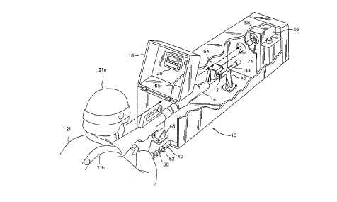
Referring to Fig. lA and 1B, the preferred embodiment of our invention
provides an electro-mechanical system generally designated 10 that
automatically
aligns a laser transmitter (SAT) 12 bolted to the stock of a small arms weapon
14
such as an M16 rifle for subsequent use by a solder in war games. The system
10
WO 95!30123 PCTNS95I05251
6
includes a rectangular hollow transit case 16 which is horizontally oriented
when
in use. A lockable hinged end cover 18 of the case 16 may be swung upwardly to
reveal a control unit 20 mounted to the inside thereof. A soldier 21 aims the
weapon 14 inside the case 16. The soldier 21 wears a helmet 21 a and a harness
21 b equipped with laser detectors which detect laser "bullet" hits in
subsequent war
games. The control unit includes a box-like housing 22 (Fig. 2) having an LCD
display 24. The housing 22 also has a keypad in the form of a membrane switch
panel. This switch panel surrounds the display 24 and includes pressure-type
switches 26, 28, 30, 32, 34, 36 and 38.
A retractable sliding rack 40 may be extended horizontally from the rear
end of a base unit 42 (Fig. 1B) mounted to the bottom wall of the case 16. A
barrel 44 of the rifle 14 is firmly supported on the apex of a rigid
triangular
' weapon rest 46 whose base is securely mounted via bolts to an intermediate
portion of the base unit 42. A trigger guard (not visible) of the rifle 14 is
mounted
in a vise 48 on the rack 40. The vise 48 has knobs 50 and 52 for manually
adjusting the azimuth and elevation, respectively, of the barrel 44 of the
rile 14.
After mounting the rifle 14 on the weapon rest 46 and vise 48, the soldier 21
(Fig.
lA) aims at an image of a target reticle 54 (Fig. 6) projected in the line of
sight
of the weapon as hereafter described in detail.
A box-shaped optics unit 56 (Figs. lA and 1B) is rigidly mounted on the
forward portion of the base unit 42 (Fig. 1B). The optics unit 56 includes a
convex
lens 58 (Fig. 6) and a beam splitter 60. The beam splitter 60 is transparent
to
infrared light from the laser transmitter (SAT) 12 (Fig. 1) but reflective to
visible
light. The target reticle 54 (Fig. 6) is mounted inside the optics unit 56
below the
axis of the laser beam. The beam splitter 60 is positioned forward of the lens
S 8
and is angled at forty-five degrees to project the image V of the target
reticle
through the lens 58 at infinity. A position sensor detector 62 in the optics
unit 56
receives the laser beam L2 and generates an error signal representative of a
WO 95!30123 ~ PC'T/US95/05251
7
displacement between a received location of the laser beam and the image of
the
target reticle. The SAT 12 is then adjusted until its laser beam L2 strikes
the
center of the detector 62.
A control circuit inside the control unit 20 (Fig. 1) is connected to an
alignment head 64 which is mechanically coupled with a rear end of the laser
transmitter (SAT) 12 bolted to the rifle 14. The control circuit causes the
alignment head 64 to repetitively trigger the laser in the laser transmitter
12.
Utilizing the error signal, the control circuit causes the alignment head to
independently rotate a pair of wedge prisms 66 and 68 (Fig. 3) in the laser
transmitter 12 to steer the laser beam in azimuth and elevation until the
laser beam
is substantially aligned with a boresight of the barrel 44 of the weapon.
The system 10 may be used for the automatic boresight alignment of all
U.S. military specified small arm weapons and machine guns with unlimited
adaptability to new weapons. The automatic operation of the system assures
rapid
(less than one minute), accurate and consistent boresighting of the SAT 12
after
a single initial sighting of the weapon 14 by the soldier 21. Use of the
sighting
vise 48 assures that optical sights and night vision devices on the weapon 14
will
not interfere with the boresighting process. The entire system 10 is continued
within the rugged transit case 16 which also serves as a sun and foul weather
shield. The system 10 does not use blank ammunition during the alignment
process and therefore it may be used at any location such as indoors on a
table top.
The initial set up of the system 10 involves three simple steps which
include installation of battery into the control unit housing 22 (Fig. 1),
activating
the BIT switch 30 (Fig. 2) and selecting the weapon type to be aligned by
depressing the switch 34. The display 24 will give appropriate text messages
and
directions to the operator as to how to proceed to the next step. Once the
system
10 is ready for alignment the soldier 21 follows the directions on the display
24
to align his or her weapon. The typical sequence is as follows:
WO 95/30123 PCT/US95105251
2i8~544
s
a) The soldier attaches the alignment head 64 to the laser
transmitter (SAT) 12;
b) The soldier places his or her weapon in the sight vise 48 and
front weapon rest 46;
c) The soldier aims his or her weapon at the image of the
illuminated target reticle 54 visible in the optics unit using the
sighting vise azimuth and elevation adjustment knobs SO and 52;
d) The soldier depresses the proceed switch 28 (Fig. 2) and follows
the instructions on the display 24. The weapon type is selected by
depressing the switch 34 at the appropriate time in response to a
query on the display;
e) The soldier backs away and depresses the align switch 26 on the
control unit housing 22;
f) The soldier waits for an "ALIGNMENT COMPLETE" message
on the display 24 which will occur less than one minute later; and
g) The soldier removes the weapon from the system following an
alignment completion instruction.
In the event any problems are encountered by the system 10 during the
alignment process such as low power, incorrect laser coding or triggering
problems, the system will inform the soldier that the weapon's SAT is
defective
and needs to be replaced.
The overall operation of the system 10 is illustrated in the block diagram
of Fig. 7. The weapon 14 is mounted in the sight vise 48 with the alignment
head
64 attached to the SAT 12. The optics unit 56 includes the illuminated target
reticle 54 at which the weapon's sights are aimed. When the align switch 26
(Fig.
2) is activated the control unit 20 causes the SAT 12 to be repetitively
triggered
while monitoring the SAT's fire LED 70 (Fig. 3) indicator for proper
operation.
The optics unit 20 senses the location of the laser and sends that data to the
WO 95/30123 PCT/US95105251
218854
9
control unit 20 which in turn determines the amount of correction needed. The
control unit 20 in turn causes the alignment head 64 to make the necessary
adjustments to the SAT 12. The process continues in real time until the SAT 12
is precisely aligned. The control unit 20, in conjunction with the optics unit
56,
also checks for laser power levels, laser codes and that the SAT' S alignment
optics
are performing as desired. The five major sub-assemblies of the system 10 are
discussed in further detail hereafter.
The optics unit 56 (Figs. 1B) is the assembly which projects the illuminated
target reticle 54 to the soldier 21 during boresighting and senses the
location of the '
weapon's laser beam with respect to the reticle. The illuminated reticle 54
assists
the soldier 21 in boresighting during reduced lighting conditions such as dusk
or
dawn. Fig. 6 illustrates the operation of the principal components of the
optics
unit 56. The single large convex lens 58 serves the function of collimating
and
focusing the laser beam to a spot at the longitudinal position sensor detector
62
which is located at the focal point of the lens 58. When the angle of
incidence to
the lens 58 of the laser beam is not perpendicular (mis-aligned) the position
of the
spot on the detector 62 is offset. The detector 62 passively quantifies the
amount
of offset and sends the error to the control unit 20. The detector is
preferably a
solid state device such as a quad-detector or it may be a linear detector with
an
analog output. Within the path of the laser beam is the beam splitter 60 which
is
reflective to visible light while allowing the infrared light from the laser
to pass
through the same. The beam splitter 60 is supported at a forty-five degree
angle
to project an image of the target reticle 54 through the same lens as the
incoming
laser. The sighting target reticle 54 is illuminated by a visible light source
such
as an LED 72 and is positioned such that the projected image is on the same
optical axis as the zero point of the position sensor detector 62. No field
adjustments of the optics unit 56 are required and the system 10 need not
contain
WO 95130123 PCT/US95/05251
2188544
to
any electronics other than the detector 62 and the LED light source 72 for
illuminating the target reticle 54.
An L-shaped protective barrier 74 (Fig. 1 ) is rigidly secured via bolts to
the
base unit 42 between the tip of the barrel 44 of the weapon and the optics
unit 56.
It prevents the soldier from inadvertently striking the lens 58 of the optical
unit
with the barrel 44 when mounting the rifle 14 on the weapon rest 46 and vise
48.
The barrier has a hole therethrough covered by a metal screen 76 for allowing
the
laser beam, which may be eight millimeters wide to pass through the same to
the
optics unit 56. Glass or some other solid transparent covering for the hole
may
not be desirable because it could become dirty, attenuate the laser beam, or
deflect
the laser beam and thereby introduce inaccuracies.
The alignment head 64 (Figs. SA and SB) is an electromechanical device
which is attached to the SAT 12 via a cable 65 (Fig. lA) and automatically
adjusts
the SAT's laser position as directed by the control unit 20. The alignment
head
64 contains an inductive coil 78 (Fig. SA) which is used to trigger the SAT's
laser
and if requested via switch 30 (Fig. 2) transfers a testing player
identification
(PID) to the SAT. The head 64 also has a detector 80 which monitors the SAT's
fire LED 70 to determine its operational status. Two miniature reduction
geared
motors 82 and 84 (Fig. SB) and an associated offset gear trains 86 and 87
within
the alignment head 64 are used to rotate non-slip couplings (not visible) on a
pair
of geared shafts 118 and 120. The couplings fit over the ends of the SAT's
adjustment shafts 106 and 108. The alignment head motors 82 and 84 are driven
and controlled by the control unit 20 during the boresighting process while
the
optics unit 56 senses the SAT's laser and provides real time feedback to the
control unit 20.
The laser transmitter (SAT) 12 (Fig. 3) includes a housing assembly 88
with a removable cover assembly 90 which forms a rear end thereof. A laser
diode assembly 92 is mounted within the housing assembly 88 and is energized
by
WO 95130123 PC'T/US95105251
2188544
11
a power circuit on a controller board 94 also mounted within the housing
assembly
88. The power circuit is actuated to energize the laser diode assembly 92 by
an
inductive switch 96 mounted to the inside of the rear cover assembly 90. The
inductive switch is actuated by energization of the induction coil 78 (Fig.
SA)
which overlaps the top on the housing assembly 88 (Fig. 3) in alignment with
the
inductive switch 96.
The forward end of the SAT housing assembly 88 (Fig. 3) is formed with
holes 98 and 100. An audio or optical sensor for detecting the firing of a
blank
cartridge is located in the hole 100 and connected to the circuit on the
controller
board 94. A transparent window 102 for permitting passage of the beam from the
laser diode assembly 92 is mounted in the other window 98. An optical sleeve
104 is positioned behind the window 102. The optical wedges 66 and 68 are
notably supported behind the window 102 for independent rotation via drive
shafts
106 and 108, respectively. The forward ends of these shafts have gears 106a
and
108a for engaging toothed peripheral portions of the optical wedges 66 and 68,
respectively. The drive shafts 106 and 108 are journaled in bearings such as
110
and 112. The rear ends of the drive shafts 106 and 108 extend through holes
(not
visible) in the rear cover assembly 90 which are sealed by O-rings 114 and
116.
These shaft ends are protected by a rigid flange 90a that extends
perpendicularly
from the rear cover assembly 90. When the alignmer_t head 64 (Figs. SA and SB)
is coupled to the rear cover assembly 90 of the laser transmitter (SAT) 12,
the
non-slip couplings (not visible) on the geared shafts 118 and 120 (Fig. SB) of
the
alignment head 64 connect with the ends of the shafts 106 and 108 to provide
driving connections to the motors 82 and 84.
Fig. 4 illustrates diagrammatically the steering of the laser beam B by
independent rotation of the optical wedges 66 and 68 via motors 82 and 84 of
the
alignment head 64. Optical wedges may be used as beamsteering elements in
optical systems. The minimum deviation or deflection experienced by a ray or
WO 95!30123 PCT/US95105251
218354
12
beam in passing through a thin wedge of apex angle BW is approximately given
by
Bd = (n - 1) B""9 where n is the reflective index. The "power" (O) of a prism
is
measured in prism diopters, a prism diopter being defined as a deflection of 1
cm
at a distance of one meter from the prism. Thus D = 100 tan(B~. By combining
two wedges of equal power (equal deviation) in near contact, and independently
rotating them about an axis roughly parallel to the normals of their adjacent
faces,
a laser beam B passing through the combination can be steered in any
direction,
within a narrow cone, about the path of the undeviated beam. The angulular
radius of this cone is approximately Bd. Apex angle is controlled to within
very
tight tolerances in the manufacturing process of the wedges. As a result of
the
melt-to-melt index tolerance, deviation angles (functions of wave-length) are
nominally specified.
The deviation angles are specified with the assumption that the input beam
is normal to the perpendicular face. At other input angles the deviation will,
of
course, be different. To determine the deviation angle for the same input
direction
but other wavelengths, the equation is: 8d = arcsin(n sin BW) - B~. where Bd
is the
deviation angle, BW is the wedge angle and B,~ the normal index at the
appropriate
wavelength. Optical wedges are available in various materials, such as
synthetic
fused silica, and in different shapes and sizes.
The control unit 20 (Fig. 1 A) provides the user-friendly LCD display 24
(Fig. 2) and controls which continuously inform the user of his weapon status
while progressively instructing him throughout the alignment process. The
control
unit 20 is mounted inside the transit case cover 18. The LCD display 24 can be
easily read when the cover 18 is in raised open position. As described above
the
control unit 20 provides all controls and monitors all activities of the
optics and
alignment head units 56 and 64. The front membrane switch panel with its
integral 4X20 LCD display 24 provides the user interface. The switch functions
are described as follows:
WO 95/30123 PCT1US95/05251
218844
13
a) ALIGN (26) - This switch is activated by the soldier after he or
she has aimed the weapon's sights at the optics units target reticle.
b) PROCEED (28) - This switch is activated any time the soldier
desires to move to the next alignment step or to acknowledge a
displayed message.
c) BIT (30) - This switch is activated during initial setup of the
system to verify its ready status.
d) PID LEARN (32) - This switch is used to transfer the system's
test PID to the SAT 12 in order to verify that the transfer function
operators. Use of this switch is optional and is only used if there
is some question as to the SAT of the cradled weapon being able
to accept other PIDs.
e) WEAPON SELECT (34) - This switch is used in conjunction
with the two arrow switches 36 and 38 to select the type of weapon
to be aligned (M16A2, M2, M240 etc.). This selection determines
which power levels and codes are to be verified by the system.
f) ARROWS (36 and 38) - These switches are used to select the
different weapon types.
The sighting vise 48 (Fig. 1B) is a stable mechanism used to hold and aim
the weapon 14 under alignment. It allows the soldier to boresight using any
aiming bias introduced by his method of aiming and eliminates any weapon
wandering away from the aim point. The vise 48 is attached to the sliding rack
40 which retracts into the transit case base unit 42 to accommodate the
different
lengths of weapons. The sight vise 48 has both elevation and azimuth
adjustment
knobs 50 and 52 allowing the soldier to accurately aim his weapon's sights at
the
image of the target reticle 54. The front portion of the weapon barrel 44
rests on
the weapon rest 46 located within the transit case 16 on the transit case base
unit 42.
WO 95130123 PCTlUS95105251
2T 8844
14
The major components of the system 10 are integral to the transit case 16
which provides a secure and rugged environment during transport and operation.
The case 16 also provides a sun and foul weather shield to allow the alignment
process to be accomplished in any expected environment. The base unit 42 is
mounted on the bottom wall of the case. The optics unit 56, weapon rest 46 and
sliding sight vise rack 40 are attached to the base unit battery (not visible)
for
powering the system is housed inside the base unit 42. The control unit 20 is
attached to the inside of the front cover 18A.
Fig. 8 is a block diagram of the optical output power and code accuracy
verification circuit of the control unit 20. An encoding circuit 122 is
connected
via a serial data bus 124 to a microcomputer (not illustrated). An optical bit
amplifier 126 in the path of the laser beam outputs signals to the encoding
electronics.
While we have described a preferred embodiment of our automatic player
identification small arms laser alignment system, it will be apparent to those
skilled in the art that our invention can be modified in both arrangement and
detail. Therefore, the protection afforded our invention should only be
limited in
accordance with the following claims.