Note: Descriptions are shown in the official language in which they were submitted.
METHOD FOR DETERMINING
WHETHER FILM IS DEVELOPED OR UNDEVELOPED
BACKGROUND OF THE INVENTION
This invention relates to a method for determining
whether the film stored in a new type of film cartridge is
a developed film or an undeveloped one.
Ordinarily, a film is stored in a snail-shaped
cartridge called "patrone" with the leading end of the film
slightly protruding from the cartridge. Use of such
conventional patrones involve various problems. Recently,
a new type of cartridge was developed which are free of
such problems. Such new type of film cartridge is
disclosed in U.S. Patent Nos. 5347334 and 5031852.
This film cartridge has a snail-shaped configuration
like patrones but is smaller than patrones. It comprises
two splittable parts so that the film wound around its
spool can be taken out if necessary. It can store not only
an unexposed film but also a developed and printed negative
film.
An unexposed film is stored entirely in the cartridge
prior to use. The film outlet is completely closed by a
lid. When the cartridge is set in a camera, the film is
1
fed out of the cartridge through its outlet by rotating the
spool with the film outlet lid open.
The film trailing end is secured to the spool by
engaging ribs protruding from a slit formed in the spool in
holes formed in the trailing end of the film. The spool
has flanges provided with edge members as film feed guides.
Disposed between one of the spool flanges and the inner
surface of the case is an arcuate disk plate carrying marks
that indicate that the film is unexposed, exposed or
developed, or bar codes for preventing double exposure.
Figs. 15 and 16 show this new type of film cartridge
M. It is disclosed in the above-mentioned U.S. Patents.
The structure of this film cartridge will be fully
understood by referring to these patent documents.
As shown in Fig. 15, the film cartridge M contains a
film take-up spool 101 in a snail-shaped cartridge case
100. Unlike patrones, the case 100 comprises two separable
halves as shown. A door 102 is provided at a film outlet
defined between the two halves when they are closed.
Rotary shafts are connected to the spool 101 and the door
102 at one end of the cartridge. The respective rotary
shafts are rotated by drive shafts that are inserted in
holes 103 and 104.
At the end of the cartridge where there are the
rotary shafts, an indicator plate 105 having a sector
2
~~~8~~~
portion is provided. Differently shaped holes a-d are
formed in an end plate 106 of the case. The holes a to d
indicate that the film is unexposed (not photographed),
partially exposed, exposed (but not developed yet), and
developed, respectively. By rotating the indicator plate
105, its sector portion, colored white, can be brought into
alignment with one of the holes a-d, so that the hole
brought into alignment with the sector portion turns white.
Thus, one can see the state of the film by checking which
hole is colored white.
As seen in Fig. 15B, the film F around a spool shaft
lOlb of the spool 101 is entirely wound into the cartridge
case 100 and completely shielded from light by closing the
film outlet with the door 102. To expose the film, i.e. to
take pictures, the door 102 is opened and the spool 101 is
rotated to push the film F out of the cartridge.
To wind film F on the spool 101, as shown in Fig.
16B, the trailing end of the film F is inserted in a slit
107 formed in the spool shaft lOlb until a rib 108 engage
in a hole h formed in the film F near its trailing end.
Then, the spool 101 is rotated. When the film is entirely
wound around the spool 101, a cutout 109 formed near the
leading end of the film F is caught by a skirt of the
flange lOlc and the film stops.
In order to develop and print a film stored in this
3
type of film cartridge, the trailing end of the film has to
be separated from the spool before feeding it into a
developing or a printing machine. But it is impossible to
automatically separate the film from the spool. Thus, in
order to effectively develop a film stored in such film
cartridge, the film has to be rewound onto e.g. an
intermediate cartridge.
A film winding device for winding a film into such an
intermediate cartridge or a similar film take-up unit is
disclosed in Unexamined Japanese Patent Publication 5-
232633. This winding device has a film cartridge
receptacle, and a film take-up unit spaced a predetermined
distance from the receptacle. Film feed rollers and a film
guide are provided therebetween and separate motors are
provided for the film cartridge and the feed rollers.
The film is fed by rotating the spool in the film
cartridge with a film cartridge motor until the film
leading end is caught by the feed rollers. Thereafter, the
film is fed to the take-up unit by rotating the feed
rollers with the feed roller motor. When the film trailing
end gets clear of the cartridge and the feed rollers, the
respective motors stop. But due to the inertia of a
flywheel provided between the spool and the film cartridge
motor, the spool tends to keep rotating for a short while
after the motors have stopped.
4
Due to this extra rotation of the spool, the rib will
disengage from the hole in the film near its trailing end.
In this state, the feed roller motor is reactivated to feed
the film until its trailing end separates from the feed
rollers. The film is thus separated from the spool in the
film cartridge.
A similar device is disclosed in Unexamined Japanese
Patent Publication 6-130633. The separator of "an engaging
device and a separator for photographic film" disclosed in
this publication has a release plate adapted to be inserted
into the film cartridge through a film outlet formed in the
cartridge case to disengage the trailing end of the film
from a rib in a slit of a spool shaft.
This new type of film cartridge is designed to
automatically feed film. A film is stored entirely in the
cartridge, irrespective of whether the film is an exposed
one or an unexposed one, unlike patrones in which films are
stored with its leading end slightly protruding from the
case. The leading end of the film is fed by rotating the
spool.
It is impossible to visually check whether the film
in such a film cartridge is developed or undeveloped.
Instead, it is determined by checking the indicator plate
provided near one end wall of the film cartridge as
described above, or by checking whether or not the
CA 02188623 1999-06-O1
cartridge has a nail (hereinafter IPI nail or simply nail).
If no nail is detected, the film is developed, and if
detected, the film is not developed.
If an undeveloped film is mistaken for a developed film
and exposed to light for e.g. printing, its images will be
lost completely. The lost images might have been an
invaluable asset for a customer. In order to prevent such an
accident, it is highly desirable to double-check if each film
is a developed one or not before it is fed out of the film
cartridge.
But such a double-check method has not yet been
established for this new type of film cartridge. Thus, in
order to positively prevent such accident, it is necessary to
double-check again if each film is a developed one or not
before it is fed into a processing machine.
An object of this invention is to provide a method of
identifying the film type which can positively identify the
type of film stored in a film cartridge of the abovementioned
new type.
SUMMARY OF THE INVENTION
According to this invention, there is provided a method
of determining whether film in a film cartridge is developed
or undeveloped, said method comprising detecting whether a
case wall of said cartridge has a nail as a first judgement of
whether said film is an undeveloped film or a developed film;
operating a film feeder for the purpose of feeding said film
6
CA 02188623 1999-06-O1
slightly out of a film feed outlet leading from said
cartridge; if said first judgement is that said film is a
developed film, emitting visible light toward a film feed
passage along which said film is fed from said outlet and
thereby determining the presence or absence of said film at
said film outlet, while also emitting infrared light toward
said film passage and thereby making a second judgement of
whether said film is an undeveloped film or a developed film;
and if said first judgement is that said film is an
undeveloped film, not emitting said visible light, and
emitting said infrared light toward said film passage and
thereby determining the presence or absence of said film at
said film outlet and also making said second judgement of
whether said film is an undeveloped film or a developed film.
In accordance with another aspect of the present
invention, there is provided an apparatus for winding a film
from a film cartridge, said apparatus comprising a detector
for detecting whether or not the cartridge has a nail as a
first judgement of whether the film is an undeveloped film or
a developed film and for producing a first signal
representative thereof; a film feeder for feeding the film out
of a film feed outlet leading from the cartridge; an infrared
light emitter to be positioned adjacent the outlet for
emitting infrared light toward a film feed passage along which
the film is fed from the outlet; a visible light emitter to be
positioned adjacent the outlet for emitting visible light
toward the passage; an infrared light receiver positioned
relative to said infrared emitter to receive therefrom
7
CA 02188623 1999-06-O1
infrared light crossing the passage and to produce a second
signal representative of the amount of received infrared
light; and a visible light receiver positioned relative to
said visible light emitter to receive therefrom visible light
crossing the passage and to produce a third signal
representative of the amount of received visible light.
Either a developed film or an undeveloped film is stored
entirely in a new type of film cartridge. Thus, it is
impossible to determine whether the film stored in the
cartridge is developed or not simply by visually checking from
outside. Thus, the cartridge is provided on its end wall with
an indicator which indicates that the film is unexposed,
partially exposed, exposed or developed, or a nail which
indicates that the film is undeveloped (if a nail is detected)
or developed (if no nail is detected).
But it is dangerous to entirely trust these indicators,
particularly a nail indicator because a nail is bent by human
hand. It is therefore desirable to check the film type
immediately before the film is developed, printed or rewound.
The abovementioned method is essential for processing the film
safely and reliably.
In the abovementioned method., if the results of detection
of a nail on an end wall of the film cartridge
7a
~w
and the detection by the sensor coincide, it is determined
that the results of detection are correct. Film type is
thus judged to be developed or undeveloped based on the
results of detections.
In a preferred arrangement of this method, if a nail
is not detected on the film cartridge and if a visible
light sensor and an infrared sensor detect that the film is
a developed film, judgment is made that the film is a
developed film, and if a nail is detected on the film
cartridge and if an infrared sensor detects that the film
is an undeveloped film, judgment is made that the film is
an undeveloped film. In this arrangement, the result of
detection of a nail is used merely as a reference.
If a nail is not detected on the film cartridge and
if a visible light sensor detects that the film is
undeveloped film, judgment is made that the film is an
undeveloped film based on the judgment by the sensors.
This is because there is a possibility that the nail may
have been erroneously bent in spite of the fact that the
film is not developed.
On the other hand, if a nail is detected on the
film cartridge and if an infrared sensor detects that the
film is a developed film, it is preferable to judge that
the film type is unidentifiable. This is because it is
less likely that an operator forget to bend the nail in
8
~~88fi~~
spite of the fact that the film is developed, compared with
the possibility of erroneously bending the nail. Thus, in
this case, it is highly probable that the infrared sensor
is malfunctioning.
Other features and objects of the present invention
will become apparent from the following description made
with reference to the accompanying drawings, in which:
BRIEF DESCRIPTION OF THE DRAWINGS
Fig. 1 is a schematic block diagram of an entire unit
for carrying out a method of identifying the type of film
of a preferred embodiment;
Fig. 2 is a flowchart showing the steps of the
abovementioned method;
Fig. 3 is a perspective view of a film rewinder for
carrying out a method of identifying the film type of the
embodiment;
Fig. 4 is a plan view of the same with the cover
plate open;
Fig. 5 is a plan view of the film rewinder showing
its inner structure;
Fig. 6 is a sectional view taken along line VI-VI of
Fig. 4;
Fig. 7 is a perspective view of a mechanism for
9
opening and closing the cartridge door by moving the knob;
Fig. 8 is a schematic perspective view of the entire
driving unit;
Figs. 9A, 9B and 9C are views showing has the trailing end of a
film is separated from the spool by the tool;
Fig. 10 is a sectional view of a rotation
transmission mechanism provided under the film cartridge;
Fig. 11 is a partial sectional view taken along line
XI-XI of Fig. 5;
Figs. 12A and 12B are view showing the operation of
the same;
Fig. 13 is a block diagram showing the relationship
between the sensor input, the control circuit and the
driving unit;
Fig. 14 is a flowchart showing the steps of the
method for identifying the film type;
Fig. 1~A is a perspective view of a film cartridge;
Fig. 15B is its sectional view;
Fig. 16A is a vertical sectional view of the same;
and
Fig. 16B is a view showing its inner structure.
DETAILED DESCRIPTION OF THE PREFERRED EMBODIMENT
Embodiments of this invention will now be described
CA 02188623 1999-06-O1
with reference to the drawings. Fig. 1 is an entire block
diagram of a control unit for identifying the kind of film
in a cartridge. The same elements used in the first and
second embodiments are denoted by the same numerals.
In this embodiment, a nail detector, a film sensor
and a film type sensor are used to reliably determine the
kind of film.
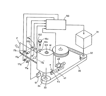
A film cartridge M houses a film, which is fed out by
rotating a rotary shaft 34 with a thrust motor 31 through
an endless belt 30 wound around pulleys 32 and 33. The
cartridge M has a spool shaft lOlb having its top end
supported by a suitable means, and a door 102 into which is
inserted a manual or motor-driven, door-opening shaft. The
film is fed out through the door 102 after the door has
been opened by rotating the door-opening shaft.
Though not shown, the cartridge M is set in a
completely light-shielded space to prevent the film in the
film cartridge from being exposed to light in case the film
should be an undeveloped one.
There are provided four pairs of sensors each
arranged in a vertical row, and comprising a front pair of
infrared LED's (light emitting diodes) 17a, a rear pair of
infrared photosensors (phototransistors) 17a', a front pair
of visible light LED's 17b and a rear pair of visible light
photosensors 17b'.
11
Numeral 51 indicates a cartridge detecting sensor
(switch) for detecting that the film cartridge M has been
set in a predetermined position, and numeral 48 indicates a
sensor for detecting a nail e. The sensor 48 is connected
to one end of a lever 41 having a protrusion 44 at the
other end. The signals from these sensors are all sent to
a control circuit 50, which, based on these signals,
controls the thrust motor 31, infrared LED's and visible
light LED's.
Now referring to the flowchart of Fig. 2, description
is made on how the film type determining unit of this
embodiment determines whether the film is a developed film
or an undeveloped one.
In the initial Step S1, the control circuit 50
determines if the cartridge has been set in position based
on the signal from the cartridge detecting sensor 51 so
that the following operation can be carried out smoothly
and reliably. In Step S2, IPI detection is made (it is
determined whether the film is a developed one or an
undeveloped one by detecting whether or not a nail is
present) based on the signal from the nail detecting sensor
48. If a nail is present, the film is judged undeveloped
and if it is not, it is judged developed.
It is possible to detect whether the film is a
developed one or an undeveloped one by using only the nail
12
~I8$~
detecting sensor or the infrared sensors. But by using
both of them, it is possible to detect the film type with
higher reliability.
If the result of IPI detection is affirmative (a nail
has been detected), information on undeveloped film is
written in a cartridge judgment register in Step S3, based
on judgment that the film is an undeveloped film. Then in
Step S4, the thrust motor 31 is activated to feed film.
When the film is fed out slightly, the infrared
sensors 17a' scan the film to determine the type of film
again (Step S5). If the sensors 17a' give the same
judgment as the nail detecting sensor, i.e. judgment that
the film is undeveloped, it is doubtless that the film is
an undeveloped film. The film is thus fed on (Step S6).
Though not shown, a display means may be provided to
display the fact that the film is an undeveloped one.
If the judgment in Step S5 is negative, i.e. the film
is judged to be a developed one, the control circuit stops
the feed of film because the judgment by the IPI detection
conflicts with the judgment by the infrared sensors 17a'.
Generally speaking, judgment by the infrared sensors is
more reliable than the judgment based on the IPI detection.
Thus, it is one way to select and adopt the judgment by the
infrared sensors if the IPI detection and the infrared
sensors deliver conflicting judgments.
13
But for safety's sake, the feed of film should be
stopped in such a case on the assumption that the IPI
detection is correct and the infrared sensors are
malfunctioning.
If the judgment by the IPI detection is negative (no
nail has been detected) in Step S2, this fact is recorded
in the cartridge judging register in Step SS3. Then, the
visible light LED's 17b are turned on in Step SS4, and the
film is fed by activating the thrust motor in Step SS5.
The infrared LED's are kept turned on all the time.
When the film is fed out slightly, the presence of
film is detected by the visible light sensors 17b' (Step
SS6) and then by the infrared sensors 17a'(Step SS7). Then
in Step SS7, the type of film is determined. If the
judgment in Step SS7 is negative, i.e. the film is judged
to be a developed one as in the IPI detection, there is no
doubt that the film is a developed one. Thus, the film is
fed on (Step S6).
If, contrary to the negative judgment in the IPI
detection, the judgment in Step SS7 is affirmative, i.e.
the film is judged to be an undeveloped one, the control
circuit judges that the film is undeveloped, respecting the
judgment by the infrared sensors 17a'. In this case, the
visible LED's 17b are turned off in Step SS8, the data in
the cartridge judging register is rewritten to the effect
14
2~88~,~
that the film is an undeveloped one in Step SS9, and the
film is fed on (S6).
The reason why the control means gives priority to
the judgment by the infrared sensors 17a' over the judgment
by the IPI detection is because the former is more reliable
than the latter.
The above-described method of determining the type of
film is carried out in the film rewinder shown in Fig. 3
and the following figures, which is an example of film
processing device for rewinding a film from a film
cartridge to an intermediate cartridge.
Since a film is wound with its trailing end in
engagement with a hook of the cartridge spool, the film has
to be manually disengaged from the hook when the film has
been fed completely out of the cartridge. It is thus
impossible to automatically feed a plurality of undeveloped
or developed films for development or printing. To
automate the developing and printing process, films in
cartridges have to be cut off at their trailing ends from
the spools and rewound to intermediate cartridges. The
film rewinder is used for this purpose.
Fig. 3 is a perspective view of the film rewinder,
Fig. 4 is a plan view partially sectioned by removing the
cover plate, and Fig. 5 is a sectional plan view showing
mechanical parts on an intermediate bottom plate. As shown
,. ~1~8~~~~
in Fig. 3, a cover plate 2 is provided to cover the front
top of the case 1. By opening the cover plate 2, one can
see a film cartridge receptacle 3 and a winding unit 4
spaced a predetermined distance from the receptacle 3 for
rewinding film to the intermediate cartridge. A film guide
is provided therebetween.
As shown in Fig. 6, the cover plate 2 has a double-
wall structure, comprising front wall 2a and a back wall
2b. A knob plate 6 having a knob 6a is provided between
the walls 2a and 2b. It is movable by a distance equal to
the width of the opening 7 shown. The knob plate 6 has an
engaging piece 6b on its back. By pulling the knob 6a to
the position shown in Fig. 4, the engaging piece 6b engages
the case 1, thus locking the cover plate 2 in the closed
position in which it closes an opening 8 of the case 1.
The cover plate 2 is pivoted about a pin 9 (Fig. 6) by arms
(Fig. 3).
Engaging pieces 11 and 12 are provided on the back of
the cover plate 2 (Fig. 3). They extend through an opening
2c formed in the back wall 2b of the cover plate 2 to
support a shoulder of the intermediate cartridge N in the
manner to be described below. A pin 13 provided on the
back of the knob plate 6 also extends through the back wall
2b. The pin 13 is used to open and close a film inlet door
of the intermediate cartridge N.
16
The knob plate 6 is formed with two elongated holes
6c in which are received pins 14 (Fig. 4) so that the knob
plate 6 is slidable back and forth between the positions
shown by solid line and two-dot chain line. On the
righthand side of the knob plate 6 is a gear train for
opening and closing the film feed door of the film
cartridge M (Fig. 7). It comprises a rack 15a, a pinion
15b and a small gear 15c.
The cover plate 2 carries on its back wall 2b a
substantially triangular fixing plate 16 having a plurality
of triangular grooves (Fig. 4). The knob plate 6 has a
protrusion 6d on its right side. By engaging the
protrusion in one of the triangular grooves of the fixing
plate 16, the knob plate 6 can be fixed in one of a
plurality of positions. In Fig. 4, numeral la designates
indicator lamps.
As shown in Fig. 3, the distance between the axes of
the film cartridge M and the intermediate cartridge N
should be as short as possible, i.e. the film guide 5
provided therebetween should be as short as possible for
the reasons to be described below. As shown, the film
guide 5 carries no feed rollers.
The film guide 5 comprises a stationary guide member
5a and a rotary guide member 5b (Fig. 5). The pressure
from the cover plate 2 when it is closed is transmitted to
17
CA 02188623 1999-06-O1
the rotary guide member 5b by .an unillustrated mechanism.
With the cover plate closed, the film is fed into the space
Sc between the two members 5a, 5b. While being fed through
the space 5c, the film is guided by the two guide members.
Numeral 17 designates an infrared sensor and 17b does an
LED type film sensor.
The cover plate of the intermediate cartridge N is
opened and closed by a pillar 18 shown in Fig. 7. The
pillar 18 is formed by bending a plate member having two
forks into the shape of the letter L. The above-mentioned
pin 13 is received in a deep groove 19a formed in the top
end of one of the upright forks 19.
The intermediate cartridge. N has its bottom supported
not on the bent bottom 18a of the pillar 18 but on an
unillustrated support member provided on the bottom of the
cartridge receptacle. The cover plates n and n' provided
at the film inlet of the intermediate cartridge N are
sandwiched between the pillar 18 and another pillar member
19. As the pin 13 is pushed down by pressing the knob 6a,
the cover n' is pushed open, so that the film F can be
inserted into the cartridge N. The case of the cartridge N
is supported at points p and p'.
As shown, the small gear 15C of the gear train 15 has
its output shaft in engagement with a rotary saft for
opening the cover plate of the film cartridge M. By moving
18
~~~~~2~
the knob 6a, the rotary shaft is rotated, so the cover
plate is opened and closed.
As shown in Fig. 5, the film guide 5 is provided with
a release guide 21 into which a tool 20 is inserted to cut
off the trailing end of the film from the spool in the film
cartridge M. The release guide 21 is arcuately shaped and
extends from the point near the end of the film guide 5
remote from the film cartridge M to the film cartridge M.
The tip of the tool 20 is moved through the release guide
21 and inserted, substantially tangential to the film inlet
end of the film guide 5, into the film cartridge M to
separate the film trailing end from the spool.
The radius of a release arm 22 is determined so that
the tip of the tool 20 comes into contact with the back of
the film when it is inserted into the film cartridge M,
that it is inserted into the film cartridge M in the
direction tangential to the direction in which the film
extends from the film outlet of the film cartridge M to the
point from which the film is unrolled from the film roll
wound around the spool, and that the radius of arc of the
release guide 21 is minimum. The release arm 22 pivots
about point 22p.
The tool 20 is coupled to the release arm 22 by means
of a pin 23 and an unillustrated spring mechanism so as to
be easily detachable for repair or replacement.
19
~~88fi~3
The release arm 22 is pivotable about the point 22b
within a predetermined angular range. The release arm 22
is in engagement near its center pin 24 with an eccentric
arm 25 pivotally coupled to a gear 27 by means of a pin 26.
The gear 27 is in mesh with another gear 28, which
has a coaxial pulley 29 around which is wound a belt 30
driven by a motor 31 through an output pulley 32. The belt
30 also extends around a pulley 33 coaxially coupled to a
rotary shaft 34 for rotating the spool of the film
cartridge M. By rotating the spool, the film F in the film
cartridge M is fed.
The winding unit 4 for the intermediate cartridge N
for rewinding the film fed from the film cartridge M to the
intermediate cartridge N has a rotary shaft 35 for rotating
the spool of the intermediate cartridge N. A belt 37 is
wound around a pulley 36 coaxially coupled to the rotary
shaft 35. The belt 37 is driven by a motor 39 through an
output pulley 38.
Fig. 8 is a perspective view showing the above-
described driving mechanism in detail. This figure will
enhance understanding of the driving mechanism of the film
rewinder.
Description is now made of the operation of the film
rewinder according to the present invention.
The film cartridge M and the intermediate cartridge N
CA 02188623 1999-06-O1
are set in the receptacle 3 and the winding unit 4,
respectively, with the cover plate 2 open. Then, the cover
plate 2 is closed and the knob 6a is pulled until the
engaging piece 6b engages the case to lock the cover plate
2.
By closing the cover plate 2, the guide member 5b of
the film guide 5 is closed as shown in Fig. 6 (normal
position). Also, by closing the cover plate 2, the
intermediate cartridge N is stably held by the engaging
pieces 11 and 12 on the back of the cover plate. Further,
by moving the knob plate 6, the doors of the film
cartridge M and the intermediate cartridge N are opened by
means of the transmission shown in Fig. 7.
Preparation for rewinding film is now complete. In
this state, the film in the film cartridge M is slightly
fed. The infrared LED sensors 1.7a check whether the film
fed from the cartridge M is an undeveloped or developed
one.
The film rewinder of this embodiment is used mainly
to rewind developed film but can be used to rewind
undeveloped one too. If the film being rewound is an
undeveloped one, its exposed images will be marred if
subjected to visible light. Thus, infrared light is used
first to check whether the film is developed or not.
If the film turns out to be a developed one, the
21
motor 31 is reactivated to feed the film again. The film
is thus guided through the film guide 5. When its tip is
inserted into the intermediate cartridge N and is caught by
its spool by a certain length, the spool is turned by the
other motor 39. The film is thus rewound around the spool
of the intermediate cartridge N.
While the film is being wound around the spool of the
intermediate cartridge N by the motor 39, the motor 31 for
the film cartridge M is rotating in the same direction as
the motor 39 to feed the film. But its revolving speed is
slightly lower than that of the motor 39. Though not
shown, the rotary shaft 34 of the film cartridge M carries
a one-way clutch that allows freewheeling of the rotary
shaft 34 while it is being driven by the motor 39 through
the film due to the speed difference between the motors 39
and 31.
When the film is nearly completely fed out of the
film cartridge M, an end mark or a small hole provided near
the trailing end of the film is detected by the infrared
sensors 17a and the film sensors 17b. Upon detection of
the end mark, the sensors 17a, 17b produce detection
signals to reverse the motor 31 for the film cartridge M.
As the motor 31 is reversed, the tool 20 is moved
through the arcuate release guide 21 and the film guide 5.
The position of the end mark, the film feed speed and the
22
tool moving speed are preset so that the film trailing end
will come to the spool end when the tip of the tool is
inserted into the film cartridge M through its door and
reaches the spool. The film trailing end is thus separated
from the spool by the tool 20 in the manner illustrated in
Fig. 9.
After the film trailing end has been separated from
the spool of the film cartridge M, the film is wound still
further and stopped with its trailing end in the film guide
5.
More detailed structure and operation of the film
rewinder of this embodiment will be described with
reference to Figs. 8-14.
First, referring to Figs. 5 and 10-12, description is
made of the mechanism for transmitting the driving force of
the motor 31, which is mainly used to rotate the spool of
the film cartridge M, to the tool 20.
As mentioned earlier, film F is fed from the film
cartridge M by rotating its spool (in the direction of
arrow in Fig. 5) with the motor 31. As shown in Fig. 10, a
one-way clutch 34a is mounted between the pulley 33
engaging the belt 30 and the rotary shaft 34.
Another one-way clutch 34b is mounted around the
rotary shaft 34 over the one-way clutch 34a. The one-way
clutch 34b has its outer ring fixed to a bottom portion 3x
23
~i8~~~~
of the receptacle 3 to allow freewheeling of the rotary
shaft 34 in the normal direction and check its rotation in
the reverse direction. On the other hand, the one-way
clutch 34a transmits only the rotation of the belt 30 in
the normal direction to the rotary shaft 34 and disconnects
the rotary shaft 34 from the belt while the latter is
rotating in the reverse direction.
To feed film from the film cartridge M, the spool 101
is rotated in the normal direction by the motor 31 through
the one-way clutches 34a and 34b. When the film is fed
nearly completely out of the cartridge and the end mark is
detected, the motor 31 is reversed.
The reverse rotation of the motor is transmitted
through the belt 30 to the coaxial pulley 29 and then
through the one-way clutch 29a to the rotary shaft 29b,
rotating the rotary shaft 29b and thus the pinion gear 28
and the gear 27. The rotation of the gear 27 causes
rotation of the eccentric pin 26. The arm 25 thus pushes
the release arm 22, pivoting the release arm 22
counterclockwise about the pin 22p.
As the release arm 22 is pivoted counterclockwise,
the arcuate tool 20 connected to the free end of the
release arm 22 is moved along an arcuate path through the
release guide 21 and the film guide 5 until its tip is
inserted into the film cartridge M through its opening (not
24
zi~8~2~
shown).
The film is thus separated from the spool of the film
cartridge M by the tool 20 in the manner that has already
been described above.
As the coaxial pulley 29 keeps rotating in the same
direction after the film F has been separated from the
spool by the tip of the tool 20, the arm 25 will now pull
the release arm 22 in the direction of rotation of the
coaxial pulley 29, so that the tool 20 is pulled back to
its original position shown in Fig. 5. In short, the
rotation of the gear 27 is converted to the pivoting motion
of the tool 20 and the release arm 22 by the arm 25.
The one-way clutch 34b is provided to prevent damage
to the film being fed out of the film cartridge M by
positively preventing the rotary shaft 34 from rotating in
the reverse direction even if the one-way clutch 34a fails
to disengage soon enough when the rotating direction of the
motor 31 is reversed and as a result the reverse rotation
of the motor 31 is transmitted momentarily to the rotary
shaft 34.
Next, description is made of a nail bending mechanism
for bending a nail a (Fig. 12A) of the film cartridge M if
it is not bent in spite of the fact that the film in the
cartridge is a developed one. (Bent nail indicates that
the film in the cartridge is a developed film.) This
~~8862
mechanism is driven by the motor 31 through the driving
force transmission mechanism for the film separating tool
20.
As mentioned above, a film cartridge M that contains
a developed film is formed with a hole d in its end plate
106. Thus, by visually checking the hole d, one can see
that the cartridge contains a developed film. But in this
embodiment, the infrared sensors 17a are used to check if
the film is a developed one instead of visually checking
the hole d.
In the arrangement of this embodiment, if the nail a
is not bent in spite of the fact that the film to be
rewound from the film cartridge M to the intermediate
cartridge N is a developed film, the nail bending mechanism
shown in Figs. 11 and 12 bends the nail mechanically, thus
eliminating the possibility of malfunction in various later
operation steps.
The nail bending mechanism is shown schematically in
Fig. 5 by chain line, and in detail in Figs. 11 and 12.
As shown, the nail bending mechanism 40 comprises a
nail bending lever 41, a nail bending protrusion 44
provided at one end of the lever 41, a roller 45 provided
at the other end of the lever 41, and a leaf spring 46
biasing the roller 45. The nail a of the film cartridge M
is bent by leverage action by pivoting the nail bending
26
lever 41 about a hinge 42 with the nail bending protrusion
44 abutting the nail e. Numeral 47 indicates a support
member.
The nail bending lever 41 is always biased by a
spring 43 to a horizontal state. When a film cartridge M
having an unbent nail a is set in the receptacle 3, the
nail bending lever 41 is pushed by the nail a into an
inclined state as shown in Fig. 12A. In this state, the
roller 45 at the other end of the nail bending lever 41
abuts the inclined end of the leaf spring 46, with the
relea~~e arm 22 at the rest position shown in Fig. 5.
When the release arm 22 begins pivoting in this
state, the roller 45 is pushed down by the inclined end of
the leaf spring 46, and the nail bending lever 41 is
pivoted to the horizontal state, so that the nail a of the
film cartridge M is pushed and bent.
If the nail a has already been bent when the film
cartridge M is set in the film rewinder, the protrusion 44
will be inserted in a recess formed in the cartridge by
bending the nail, so that the nail bending lever 41 will
not incline, i.e. be kept horizontal by the spring 43.
When the nail bending lever 41 is moved together with
the release arm 22 to bend the nail, its movement is
detected by the sensor 48.
Before feeding the film, the type of film is
27
CA 02188623 1999-06-O1
determined in the above-described manner by the control
unit, which is actually a microcomputer.
Since the entire control operation has already been
described, description is now made of the specific film
type determining method with reference to the block diagram
of Fig. 13 and the flowchart in Fig. 14.
Fig. 13 shows in block diagram the relationship
between the sensor input, the control circuit 50 and the
driving unit. Fig. 5 shows by dotted lines a cartridge
detector 51, an intermediate cartridge detector 52, a slide
lever detector 53, an IPI detector 48, a tool stand-by
position detector 54, a tool insert position detector 55
and a forced start switch 56.
Detection signals from these detectors 51-55 are sent
to the control circuit 50 through an input buffer 57. In
response, the control circuit 50 sends control signals to a
motor driving circuit 59 through an output buffer 58. Thus
the motors 31 and 39 are driven.
The infrared LEDs 17a and the visible light LEDs 17b
are turned on by output buffers 60 and 61. The infrared
LEDs 17a are kept on all the time. Detection signals from
the infrared sensors 17a' and visible light sensors 17b',
which are light-intercepting sensors, are gent through
input amplifiers 62 and 63 to the microcomputer as the
control circuit 50. L1 - L3 indicate error lamps.
28
~i88~~~
The tool stand-by position detector 54 and the tool
insert position sensor 55 are not used in determining the
film type but are shown for reference.
The flowchart shown in Fig. 14 is basically the same
as the flowchart shown in Fig. 2 but includes the following
added functions, which are necessary when the film type
determining method is applied to a film rewinder.
That is, the flowchart in Fig. 14 includes added Step
S0, in which the slide lever is detected and Step S1', in
which the intermediate cartridge is detected before IPI
detection in Step S2. Also, if it is found out that the
nail has been bent (NO) in the IPI detection in Step S2,
the forced start switch is pressed in Step SS2. This is
because even if the IPI detection indicates that the film
is a developed one, judgment by the IPI detection may be
wrong. Thus it is beneficial to turn on the indicator
lamps by pressing the forced start switch to attract the
attention of an operator.
Also, the flowchart of Fig. 14 differs from that of
Fig. 2 in that the rewinding of the film is continued in
Step S6 but after bending the nail in Step S7.
As described above, film type is determined both by
checking whether of not the film cartridge has a nail and
by directly checking by sensors whether the film is a
developed film or an undeveloped one. Thus, it is possible
29
~i~8~2~
to accurately determine the film type before processing the
film. The film can thus be processed safely and reliably.