Note: Descriptions are shown in the official language in which they were submitted.
.. 2188625
FLEXIBLE TAPE APPLICATOR AND METHOD OF OPERATION
BACKC ROUND OF THE INVENTION
Technical Field
The invention relates generally to a device for applying a
flexible tape onto a planar :>heet. More particularly, the invention relates
to a
s device for laying a deformable, flexible adhesive tape onto a planar sheet
under
constant tension. Specifically, the present invention relates to a device for
applying an insulating tape onto a planar glass sheet as part of the
manufacturing process of multi-pane windows.
o Background Information
The need arises in a variety of manufacturing environments to
apply a flexible tape onto a planar sheet. For example, adhesive tape is often
utilized to attach machine components to one another. Additionally, it is well
~s known to apply insulating and vibration isolating strips to a variety of
machines
and building components to either entrap liquids and gases, or alternatively
to
seal out contaminants. Adhesive elastomeric flexible tapes are also often
applied to access panels on rnachine housings such as air conditioning units
and
compressors when '.he machine housing will be subject to weather, or harsh
zo manufacturing environments. Additionally, such flexible tapes are often
applied
between parallel panes of glass when manufacturing insulated windows and
doors.
SpE~cifically, a number of production steps are required in the
manufacture of gla:~s units for placement within window and door frames.
as Thermally insulated, single and multi-pane window and door units include a
number of structural elements: wood, aluminum or vinyl frames to encase the
glass window; metal spacers which are spaced between the multi-pane glass
2188625
panes and along thc~ peripheral edge thereof, muntin and mullion strips placed
between and conti~auous to each glass sheet of the multi-pane window for
providing an ornamental appearance, and sealant tape material applied to the
perimeter edge of the glass sheets of the multi-pane unit.
s Recent innovations in the manufacture of thermally insulative
multi-pane window:. includes suspension of a polyester film coated with a heat
insulative material between the panes of glass, and filling the space
therebetween with ~~ low conductivity gas, such as argon or krypton, to form a
barrier to conductive heat transfer. The film placed between the glass sheets
o provides a barrier to radiative heat transfer through the window to the
external
environment.
It is well known in the manufacture of single or multi-pane
window units that the manner of treatment and construction of the perimeter
edges is critical to the performance of the window. The manner in which the
perimeter edges ovf the glass sheets are made can have a performance
degradating effect on the glass sheet when installed in an insulated door or
window unit. The perimeter .edge of the glass sheet can have a great impact on
the overall thermal performance of the insulating window insofar as the center
of the glass may register a higher value, yet the edges of the glass will be
colder.
ao ThE~ thermal performance of the edge portion of the glass is
particularly affected by the manner and method by which the tape material is
applied to the perimeter edge of the glass panes. Sealant tape material for
application on the perimeter edge of the glass may be manufactured of a
variety
of materials including polyisobutylene, or butyl hot melt, adhesive or a
Zs polymerizable plastic: material injected by a nozzle placed adjacent the
perimeter
edge of the glass sheet. By way of example, one such sealant strip is
manufactured by Tre~mco, Inc. and is sold under the trademark Swiggle~ Strip.
Swiggle~ Strip has been found to be a convenient product in the manufacturing
of double glazed windows. ~~t room temperature, the product has considerable
3o adhesive properties and is applied to the glass sheet to provide a hermetic
barrier to the area where the frame fits around the perimeter edges of the
glass
2
v -w 2188625
sheet. Moisture seepage aind conductive heat loss are thus prevented by the
air-tight adhesion of the sealant strip to the glass sheets. Additionally, the
sealant strip assures that the low conductivity argon or krypton gas remains
trapped between the' windovv panes.
s In a multi-pane window, the sealant tape material is applied to
the perimeter edge of one glass sheet to provide an air and water tight
hermetic
seal between the edges of the glass sheet on which it is laid, and a second
sheet positioned on i:op of the sealant tape. Adhesive properties of the
sealant
tape material are designed to prevent fogging problems from developing due to
~o a sealant tape leak, Either between the sealant tape and the edge of either
one
or both of the glass sheets or between the sealant tape and the wood, aluminum
or vinyl frame unit in which the multi-pane window is encased. When the
hermetic adhesion of the sealant tape material fails, moisture in the air
condenses in the space befiroeen the glass panes, and fogging occurs. Thus,
~s the quality of the multi-pane window is marred by the fogging occurring
between
the glass sheets, and also, the heat insulative qualities of the multi-pane
window
are degraded by the sealant tape leak.
From the foregoing, it is obvious that the application of the
sealant tape material is a critical problem in the overall manufacture and
thermal
ao performance of any glass unit, whether a single pane or multi-pane glass
window.
ThEr prior art discloses a number of devices for applying a
sealant tape materiel to the perimeter edges of glass sheet material. Some
examples of the prior' art are U.S. Patent No. 3,886,113 to Bowzer, U.S.
Patent
as No. 3,990,570 to Mercier, U.S. Patent No. 4,088,522 to Mercier, U.S. Patent
No.
4,145,237 to Mercies and U.:S. Patent No. 4,546,723 to Leopold.
In the past, Swiggle~ Strip has been applied by hand.
Specifically, the strip is rolled off of a roll, aligned along the edge of the
glass by
hand and pressed down to adhere to the glass. Once the strip has been applied
3o around the entire perimeter of the first pane of glass, the second pane is
placed
on top of the strip, and the entire unit is heated to bond the strip to the
glass.
3
2188 625
While this method is presumably adequate for the purpose for which it is
intended, it is disadvantageous because of inconsistencies in the placement of
the strip relative to the edge of the pane, and because of the extensive time
required to accurately place the insulated tape.
As a result of the difficulties in manually applying the insulating
strip, various devices have been developed in an attempt to facilitate the
application process. One such device is disclosed in U.S. Patent No. 4,756,789
to Kolff.
While this device is also presumably adequate for the purpose
o for which it was intended, it remains relatively time consuming, and
contains the
further problem thaw this device is designed to slide along the surface of the
glass as the insulating strip is applied. Because many panes on which an
insulating strip is applied are coated., for example by applying the polyester
film
coated with a heat insulated material between the panes of glass, a device
which
~5 rubs along the surface of the glass has the potential of scratching or
otherwise
damaging these coatings.
they need thus exists for an applicator which will automatically
apply flexible tape material to a planar sheet such as an insulating strip to
a
glass pane without contacting the glass pane. Additionally, the need exists
for
2o an applicator which will apply insulating flexible tapes to a glass pane
along a
predetermined path, and which assures that the strip remains accurately
positioned adjacent the edge of the glass pane, and which will accurately form
each corner thus providing a continuous strip about the perimeter of the glass
pane.
SUMMARY OF THE INVENTION
Objectives of the invention include providing an automated
applicator for applying flexible tape material to a planar sheet.
3o A further objective is to provide an applicator for applying
flexible insulating tape to them perimeter of a glass pane.
4
.. 218~6Z5
Another objective is to provide an applicator for bringing the
edge portion of a flexible tape into contact with a planar sheet.
Yet a further objective is to provide an applicator which will
accurately bend the flexible tape adjacent each corner of the planar sheet.
s Stil'I another objective is to provide an applicator for applying a
flexible tape to a glass panes wherein the flexible tape is swiggleO seal.
Still a further objective is to provide an applicator which
maintains a constant tension on the tape such that the tape is neither
stretched
nor compressed duiring application thereby assuring that the tape maintains a
o constant cross-sectional configuration.
A still further objective is to provide an applicator in which
constant pressure is. appliedl to the tape during application to the glass
pane.
Yei: another objective is to provide an applicator in which a
sensor is associated with a pressure roller to assure that the pressure roller
is
~5 rotating.
Another objjective is to provide an applicator which moves the
spool with the applicator head thereby minimizing the distance traveled by the
flexible tape from the= spool 1:o the application zone.
Still a further objective is to provide an applicator in which the
ao glass remains in the horizontal plane when flexible tape is applied
thereto.
A still further objective is to provide an applicator which
registers the placement of marks onto the flexible tape relative to the
movement
of the head through the Cartesian coordinate system, rather than equally
spacing the marks along predetermined lengths of the flexible tape.
z 5 Another objective is to provide an applicator head having a
motor for unreeling flexible tape, the speed of operation of which is
initially set
to correspond to the speed of the robotic arm.
Still a further objective is to provide an applicator in which the
speed of the motor unreeling flexible tape from the spool increases and
3o decreases in response to the tension on the flexible tape and the amount of
X188625 ~"
flexible tape on the spool to assure that the flexible tape remains in
constant
tension.
~~nother objective is to provide an applicator having an
applicator head mounted onto a programmable robotic arm.
~~till another objective is to provide an applicator which is of
simple construction, which achieves the stated objectives in a simple,
effective
and inexpensive manner, and which solves problems and satisfies needs
existing in the art.
These and other objectives and advantages of the invention are
~o obtained by the improved flexible tape applicator of the present invention,
the
general nature of which may be stated as including an applicator head having
a path of travel, a flexible tape path extending at least partially through
the
applicator head, and an application zone; a table adapted to retain the sheet
adjacent the applicator head; first drive means for moving the applicator head
i5 relative to the sheet along the path of travel at preselected speeds; data
collection means for collecting data related to the speed of the first drive
means;
second drive mean:; for driving the flexible tape; and a control means
operatively
connected to the second drive means for receiving data from the data
collection
means and for altering the speed of the second drive means in response to said
zo collected data and for maintaining a proportional relationship between the
speed
of operation of the second drive means and the speed of operation of the first
drive means wherE:by the tension on the flexible tape remains substantially
_ constant throughout the path of travel of the applicator head.
s
r,
In another ash>ect of the invention there is provided a method of
applying a flexible; tape 1;o a sheet comprising the steps o~ moving an
applicator head having a flexible tape path along a predetermined path while
simultaneously applying flexible tape to the sheet at predetermined speeds;
measuring the tension on t:he flexible tape along the flexible tape path and
creating a tension signal; forwarding the tension signal to a control unit;
providing a flexible tape drive means for driving the flexible tape to the
applicator head while applying the flexible tape to the sheet; and controlling
the
speed of the flexiblf; tape drive means with the control unit in response to
said
tension signal for maintaining a proportional relationship between the speed
of
operation of the flexible l:ape drive means and the predetermined speeds
whereby the tension on ithe flexible tape remains substantially constant
throughout the path of travels of the applicator head.
BRIEF DESCRIPTION OF THE DRAWINGS
The preferred embodiment of the invention, illustrative of the
best mode in which applicar.~ts have contemplated applying the principles, is
set
forth in the follov~~ing description and is shown in the drawings and is
particularly and distiinctly pointed out and set forth in the appended claims.
6a
._ 2188 b25
FIG. 1 is a perspective view of the robotic arm with portions
broken away and in section, and shown with an applicator head in dot-dash
lines, and in combination with a planar sheet support table;
FI(~. 2 is a side elevational view of the applicator head with the
s printer removed;
FI(~. 3 is a aide elevational view of the applicator head opposite
the side elevational view shown in FIG. 2;
FICA. 4 is an end elevational view of the applicator head shown
in FIG. 2;
o FICA. 5 is an end elevational view of the applicator head
opposite the end elEwational view shown in FIG. 4;
FICA. 6 is a top plan view of the applicator head shown in FIG.
2;
FICA. 7 is ain enlarged view with portions broken away and in
section, of the encir~~led porlrion shown in FIG. 2;
FIC~. 8 is an enlarged side elevational view of the applicator
head shown in FIG. 2;
FIC~. 9 is an enlarged bottom plan view of the applicator head
with portions broken away, and looking in the direction of line 9-9, FIG. 8;
ao FIC~. 10 is <~n enlarged end elevational view of the applicator
head with portions broken away and looking in the direction of line 10-10,
FIG.
8;
FIG. 11 is an enlarged end elevational view of the applicator
head with portions broken away and in section, and looking in the direction of
25 line 11-11, FIG. 8;
FIG. 12 is an enlarged view of the applicator head similar to
FIG. 2 shown in a fir;~t position;
FIG. 13 is an enlarged side elevational view similar to FIG. 12
shown in a second position uvith the printer removed;
3o FIG. 14 is an enlarged side elevational view similar to FIG. 13
shown in a third position;
218 8 62~
FIG. 15 is an enlarged end elevational view similar to FIG. 5
shown in a fourth position;
FIG. 16 is .an enlarged side elevational view similar to FIG. 13
shown in a fifth position;
s FI(3. 17 is an enlarged side elevational view similar to FIG. 13
shown in a sixth position;
FI(~. 18 is an enlarged view of the applicator head shown in the
position in FIG. 19 Looking in the direction of line 18-18, FIG. 17;
FICA. 19 is an enlarged side elevational view similar to FIG. 13
o shown in a seventh positian;
FICA. 20 is an enlarged view of the applicator head in the
position shown in FIG. 21 looking in the direction of line 20-20, FIG. 19;
FIC~. 21 is an enlarged side elevational view similar to FIG. 13
shown in a eighth position;
is FIC~. 22 is an enlarged view of the applicator head in the
position shown in FIG. 23 looking in the direction of line 22-22, FIG. 21; and
FIC~. 23 is an enlarged side elevational view similar to FIG. 14
shown in a ninth po;;ition.
Similar numerals refer to similar parts throughout the drawings.
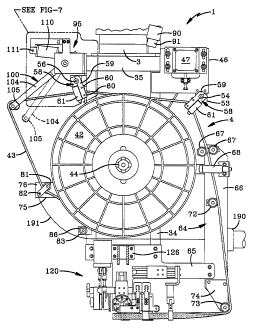
DESCRIIPTION OF THE PREFERRED EMBODIMENT
The improved flexible tape applicator of the present invention
is indicated generally at 1, and is parCicularly shown in FIGS. 1-6.
Applicator 1
includes a robotic arrn 2, having a mounting pad 3. Mounting pad 3 is sized to
receive an applicator head 4, shown schematically in dot-dash lines in FIG. 1.
A support table 5 is ~~ositione~d below applicator head 4 for supporting a
planar
sheet 6 thereon. While support table 5 may have a variety of sizes and
configurations, in the' preferred embodiment it is either a roller table or an
air
3o table for supporting planar sheet 6, and is part of a conveyor unit
extending
outwardly beyond ro~~otic arm 2 such that glass sheets may be moved along the
s
218~~25
top surface of support table 5 from a previous work station, to a position
beneath
applicator head 4, to a subsequent position in a manufacturing line.
Robotic arm 2 may have a variety of sizes and configurations,
and must have at least threE: degrees of freedom to assure that applicator
head
s 4 is movable through the Cartesian coordinate system. In the preferred
embodiment, robotics arm 2 i;~ manufactured by Nachi Robotics of 22285 Roethel
Drive, Novi, MI 48375 under the Model No. SA-130.
Inasmuch as robotic arm 2 is commercially available, a
description of the s;~me will be given only in summary, and only to the extent
o necessary to understand the invention. Robotic arm 2 includes a base 10
having
a stationary mounting pad 11 and a bearing plate 12 rotatably mounted on
mounting pad 11 to provide movement of bearing pate 12 relative to mounting
pad 11 in the direction of arrow A shown in FIG. 1. While mounting pad 11 may
be mounted to a variety of ;>urfaces including floors, walls and ceilings, in
the
preferred embodiment, mounting pad 11 is secured to horizontal support surface
13. A carriage 14 is secured to bearing plate 12 and rotates therewith. A
first
motor 9 operatively communicates with bearing plate 12 such that first motor 9
rotates bearing plate 12 relative to mounting pad 11. A base arm 15 is
pivotally
secured to carriage 14 via a pivot pin 16 and is counterbalanced against
zo uncontrolled movement via counterbalance 17. A second motor 18 operatively
communicates with vase arm 15 to move base arm 15 in the direction of arrow
B shown specifically in FIG. 1.
An upper arm 21 is secured to base arm 15 via a pivot pin 22
with a third motor 23 providing rotational movement of upper arm 21 relative
to
25 base arm 15 in the direction of arrow C shown specifically in FIG. 1. As
can be
seen from the above discussiion, first motor 9, second motor 18 and third
motor
23 operate to move upper arm 21 through the Cartesian coordinate system.
A plurality of concentric drive shafts 24 extend along the length
of upper arm 21 and extend between a fourth motor (not shown) and a wrist
3o section 25. Drive shafts 24 operate to rotate wrist section 25 in the
direction of
arrow D (FIG. 1 ). Mounting pad 3 may also be rotated in the direction of
arrow
9
. ~ z ~ aa6~5
E. Robotic arm 2 thus provides a plurality of motors to move mounting pad 3
throughout the Cartesian coordinate system in the direction of arrows A, B and
C (FIG. 1). Additionally, wrist section 25 may be rotated in the direction of
arrow
D with mounting pad 3 also movable in the direction of arrow E. Robotic arm 2
s is first moved in the direction of arrows A, B and C to position the head
relative
to the workpiece, and is then operated to orient mounting pad 3 relative to
support table 5 by operating wrist section 25 to move in the direction of
arrow D,
and by rotating mounting pad 3 in a direction indicated at arrow E.
Having novv generally described robotic arm 2, applicator head
0 4 includes a U-shaped frame 30 (FIGS. 2-6) having a body 31 and a pair of
parallel and spaced apart upper and lower legs 32 extending outwardly
therefrom whereby body 31 and upper and lower legs 32 define a U-shaped
cradle 33. Body 31 includes a pair of parallel and spaced apart vertical beams
34, and a pair of end brackets 35 extending intermediate vertical beams 34
adjacent each end thereof. IJpper leg 32 includes a pair of parallel and
spaced
apart substantially horizontal support beams 36, each of which is attached to
one
side of body 31. Referring specifically to FIGS. 3 and 4, a U-shaped mounting
bracket 37 is mountE~d to they exterior of body 31 and includes a bearing set
38
mounted thereto. An axle 41 extends through U-shaped mounting bracket 37
ao and body 31 and is rotatably supported within bearing set 38. A spool 42 of
a
flexible tape 43 is fixedly mounted on axle 41 within cradle 33 and
intermediate
upper and lower legs 32. Spool 42 is retained on axle 41 via a hand knob 44
threadably secured an the end of axle 41. Hand knob 44 is removable to permit
spool 42 to be replaced as required.
25 A drive pulley 45 is also mounted to axle 41 within U-shaped
mounting bracket 37. A motor mounting plate 46 (FIG. 5) is secured to body 31
and supports a drive motor 47. Drive motor 47 includes a drive shaft 48 with a
drive pulley 49 mounted thereon whereby drive pulley 49 is coplanar with
driven
pulley 45. A drive bE~lt 52 extends around driven pulley 45 and drive pulley
49
3o such that activation of drive motor 47 will cause drive shaft 48 and
interconnected drive pulley 49 to rotate. Rotation of drive pulley 49 causes
io
21$8625
driven pulley 45 and interconnected axle 41 to rotate. As axle 41 rotates,
spool
42 rotates therewith thereby unwinding flexible tape 43.
A IJ-shaped roller mounting bracket 53 (FIG. 5) is secured to
motor mounting plate 46 and retains a slide rod 54 above spool 42. A U-shaped
s mounting plate 53 also extends outwardly from the side of body 31 via bolts
55
(FIG. 6). A slide rod 56 extends through apertures formed in U-shaped mounting
bracket 53 and is substantially parallel to slide rod 54 and is supported
above
spool 42.
A coil spring 57 extends over each end of slide rod 54 and 56
io and is coaxial therevuith. A follower 58 is slidably mounted on each slide
rod 54
and 56 and includes a pair of parallel and spaced apart sidewalls 59 (FIGS. 4
and 5), and a pair of horizontal support rollers 60 mounted therebetween. A
pair
of parallel and spaced apart vertical guide rollers 61 extend upwardly on
either
side of support rollers 60 anti are spaced apart a distance equal to the width
of
~s flexible tape 43. Support rollers 60 thus engages flexible tape 43 along
its width
with each vertical guide roller 61 engaging an edge of flexible tape 43. Each
follower 58 is slidably mounted on a slide rod 54 and 56 and moves along the
associated slide rod in response to movement of flexible tape 43 across the
axial
length of spool 42. ~~pecifically, as spool 42 rotates via its interconnection
with
zo drive motor 47, each revolution of spool 42 will unwind an additional wrap
of
flexible tape 43. As each successive wrap of flexible tape 43 is removed from
spool 42, the point at which flexible tape 43 is removed from spool 42 will
displace axially along the lern~th of spool 42. As the point of removal from
spool
42 axially displaces, followers 58 respond thereto by moving along the length
of
as slide rods 54 and 5E~. Coil springs 57 prohibit the associated follower 58
from
sliding off of the associated slide rod 54 or 56 respectively.
An L-shaped roller support plate 64 is mounted to body 31
adjacent lower leg 3~'. and includes a horizontal portion 65 and a vertical
portion
66. Referring specifically to FIGS. 3 and 5, a pair of parallel and spaced
apart
3o guide rollers 67 whi<;h have a center axis substantially parallel to axle
41 are
mounted to the top oaf vertical portion 66 of roller support plate 64. Guide
rollers
m
2 I x$625
67 thus engage flexible tape 43 across its width. A U-shaped bracket 69 is
mounted to roller support plate 66 just below guide rollers 67. A pair of
second
guide rollers 68 having a center axis substantially perpendicular to axle 41
are
mounted to U-shaped bracket 69 with each roller 68 engaging an edge of
flexible
s tape 43. A third guide roller 72 and a fourth guide roller 73 are attached
to roller
support plate 64 and are parallel to and spaced apart from first guide roller
67
with roller 73 being rnounted to the bottom of a roller support plate 64 via a
roller
mounting plate 74.
A first roller support bracket 75 extends outwardly from body 31
to of frame 30 opposite first roller support plate 64 (FIGS. 2-4). First
roller support
bracket 75 includes a pair of parallel and spaced apart sidewalls 76.
Sidewalls
76 support a, rod 80 having a roller 81 rotatably mounted thereon. A separator
roller 82, parallel to and spaced apart from rod 80, is also supported from
sidewalls 76 of first roller support bracket 75. A second roller support
bracket 83
is having a pair of sidewalls 84 supports a rod 85 having a separator roller
86
rotatably mounted thereon. Separator rollers 86 and 82, and roller 81 are
cantileverly supported outwardly from first and second roller support brackets
75
and 83 respectively.
A mounting pad 87 (FIG. 6) is secured intermediate horizontal
2o beams 36 of upper I~~g 32 and is complementary related to mounting pad 3 of
robotic arm 2. A complementary relationship between mounting pad 87 of
applicator head 4 and mouni:ing pad 3 of robotic arm 2 assures that applicator
head 4 may be mounted to robotic arm 2 for movement through the Cartesian
coordinate system and for rotation about a center axis.
z5 A first optical or acoustic sensor 90 is positioned adjacent the
end of one horizontal beam 36. Sensor 90 includes a beam output 91 (FIGS. 4-
6) positioned to projE~ct a beam onto spool 42 of flexible tape 43.
Particularly,
sensor 90 projects a beam onto the wrap indicated generally at A' on FIG. 4
which is positioned adjacent the end of spool 43. Similarly, an optical or
acoustic
3 o sensor 92 having a beam output 93 is positioned on horizontal beam 36
whereby
the beam exiting sensor 92 is projected at the wrap of flexible tape 43
adjacent
12
_. 218625
the other end of spool 42 which wrap is indicated generally at B' in FIG. 4.
Both
sensors 90 and 92 are electronically connected to a control unit 94 (FIG. 6)
also
connected to drive rnotor 47. Control unit 94 is also connected to, and
receives
information from, robotic arm 2. Specifically, control unit 94 receives
information
s related to the vector velocity of robotic arm 2 to initially set the speed
of drive
motor 47.
Referring fro FIGS. 3 and 7, a dancer arm assembly 95 is
attached to body 31 of framed 30 opposite the point of attachment of drive
motor
47 to body 31 of frame 30. Dancer arm assembly 95 includes a center pivot
to bracket 96 and an L-shaped cylinder bracket 97 extending outwardly
therefrom.
Center pivot bracket 96 includes a pair of parallel and spaced apart legs 98.
A
pivot pin 99 is mounted to and extends between legs 98 for pivotally
supporting
a dancer arm 100. Cancer arm 100 is formed with a U-shaped mounting bracket
101 having a pair of parallel .and spaced apart legs 102. Legs 102 of U-shaped
is mounting bracket 101 extend intermediate legs 98 of center pivot bracket
96.
Each leg 102 is formed with a hole 103 for receiving pivot pin 99. Pivot pin
99
thus extends through legs 98 of center pivot bracket 96, and through logs 102
of U-shaped mounting bracket 101 to provide pivotal movement of dancer arm
100 relative to cenver pivot bracket 96. A U-shaped dancer frame 104 is
ao mounted to U-shaped mounting bracket 101, and supports a dancer roller 105
across the open end thereof.
A cyylinder 110 is mounted at a pivot 111 to L-shaped cylinder
bracket 97 and includes a rod 112 mounted intermediate legs 102 of U-shaped
mounting bracket 11)1 of dancer arm 100 via a pivot pin 113. Pivot pin 113
as extends through rod 112 and a hole 114 extending through each of legs 102.
Deflection of dancer arm 100 thus causes rod 112 to insert into, and retract
out
of, cylinder 110. Are electronic sensor 115 is associated with cylinder 110 to
measure the movement of rod 112 relative to cylinder 110 and forward such
measured data to control unit 94. Alternatively, the radial position of dancer
arm
30 100 may be measurE~d and forwarded to control unit 94.
13
21 ~8 625
Referring to FIGS. 3-4, a printer bracket 126 is attached to
horizontal portion 65 of roller support plate 64 and supports an applicator
assembly 120. Referring sF~ecifically to FIGS. 8-12, and in accordance with
one
of the features of the present invention, a pneumatic cylinder 121 is mounted
to
s a bracket 126 (FIG~~. 10 and 11 ) and includes a piston cylinder rod 122
mounted
to a retainer clip 123. A printer 124 is mounted within retainer clip 123 with
the
operating end extending downwardly toward flexible tape 43 as described in
detail below. Printer' 124 may take a variety of sizes and configurations
including
thermal printers and inkjet printers, with an inkjet printer being utilized in
the
~o preferred embodiment. A slide rod 125 extends outwardly from retainer clip
123
and is substantially perpendicular to mounting bracket 126 and is received
within
an aperture formed in a slidle block 127. Pneumatic cylinder 121 thus causes
printer 124 to move l:oward and away from flexible tape 43, with the
engagement
between slide rod 1a!5 and snide block 127 assuring that the movement of
printer
124 is substantially perpendlicular to mounting bracket 126. A control unit
128
is provided to activate printer 124 at preselected distances of travel of
applicator
head 4 for purposes described below.
A second pneumatic cylinder 130 (FIG. 8) is mounted to
horizontal portion 6~i of roller support plate 64 and includes a cylinder rod
131
ao attached to a mounting axle 132. A pair of slide rods 134 move within a
guide
block 135 mounted on horizontal portion 65 to guide the movement of mounting
axle 132 when acte~j on by second pneumatic cylinder 130. A pressure roller
136 is rotatably mounted on rnounting axle 132 and remains substantially
vertical
when second pneumatic cylinder 130 is in both the extended and retracted
25 position. Pressure roller 136 engages the upper edge portion of flexible
tape 43.
A third pneumatic cylinder 140 is mounted to horizontal portion
65 of roller support plate 64 and is mounted substantially horizontal and
includes
a cylinder rod 141 (I=IG. 8). Cylinder rod 141 is attached to a mounting block
142 at a pivot 143. Mounting block 142 carries a pincher pin roller 144 which
3o extends downwardly from they lower end of mounting block 142. Mounting
block
142 is rotatably mounted to roller support plate 64 via a cylindrical rod 145.
14
_. 2~~~6z~
Mounting block 142 is rotata~~bly mounted to cylindrical rod 145 intermediate
pivot
143 and pincher pin roller 144. Operation of third cylinder 140 thus causes
cylinder rod 141 to move thereby causing mounting block 142 and associated
pincher pin roller 144 to rotate about cylindrical rod 145.
s A 'fourth pneumatic cylinder 146 is mounted to roller support
plate 64 and is substantially parallel with third pneumatic cylinder 140 and
includes a cylinder rod 147. Cylinder rod 147 is attached to a mounting block
148 at a pivot 149. Similar to mounting block 142, mounting block 148 is also
pivotally mounted on cylindrical rod 145 and carries a pincher roller 150.
to Activation of fourth pneumatic cylinder 146 thus causes cylinder rod 147 to
move
within pneumatic cylinder 146 thereby causing mounting block 148 and
interconnected pincher roller 150 to rotate about pivot 145.
A t7fth pneumatic cylinder 153 is supported from horizontal
portion 65 of roller :support plate 64 and includes a cylinder rod 154.
Cylinder
~s rod 154 is pivotally mounted to a pair of independently mounted movable
mounting blocks 1 ~i5 via a pair of pivots 156. Each mounting block 155 is
pivotally mounted on a stabilizer block 158 and has a pincher roller 157
mounted
thereon. Activation of fifth pneumatic cylinder 153 thus causes cylinder rod
154
to move into, and out of pneumatic cylinder 153. As cylinder rod 154 moves,
ao mounting blocks 1;i5 pivot about stabilizer block 158 thereby raising and
lowering pincher rollers 157 in the manner described below. Additionally,
fifth
pneumatic cylinder 153 and interconnected pincher rollers 157 are mounted to
a pair of horizontall~,r extending slide rods 159 which are received in
through
apertures formed in a guide block 160. Slide rods 159 may be moved within
as guide block 160 to rnove the position of pincher rollers 157 relative to
pincher
roller 150 and 144. Movement of slide rods 159 may be manual, or automatic
via a pneumatic cylinder 8 (FIG. 8) in order to move pincher rollers 157
between
a forward and retracted position. A horizontal roller 163 is rotatably mounted
on
a mounting bracket 164 to contact the upper edge of flexible tape 43, and is
3o positioned intermediate pincher roller 150, and pincher rollers 157.
21 ~~ 625
RE~ferring to FIGS. 8 and 9, a first stationary roller 165 is
positioned adjacent pincher pin roller 144 and is spaced from roller 144 a
distance equal to the width of flexible tape 43. Additionally, pressure roller
136
is positioned intermediate pincher pin roller 144 and first stationary roller
165
s thereby defining an application zone 167. Application zone 167 is the area
where flexible tape 143 is applied to planar sheet 6. A second stationary
roller
166 is positioned adjacent pincher roller 150 and is also spaced apart
therefrom
a distance equal to the width of flexible tape 43.
A pressure roller 136 is formed with a plurality of holes 168. A
to third optical sensor '169 (FIG. 9) projects an optical beam at pressure
roller 136
adjacent the point where holes 168 will pass thereby. The optical beam
projected at pressun~ roller 136 will alternatively reflect off of roller 136,
and pass
through a hole 168. Optical sensor 169 assures that by receiving alternative
signals, pressure roller 13fi is rotating. Alternatively, if optical sensor
169
is receives a constant: lack of reflection, in a situation where the optical
beam
constantly passes through holes 168, a control signal is forwarded to control
unit
94 to stop the movement of applicator head 4 as these signals reflect that
pressure roller 136 is not roi:ating.
Referring next to FIGS. 10 and 11, a hydraulic cylinder 174 is
ao mounted to horizontal portiion 65 of roller support plate 64 and includes a
cylinder rod 175. Cylinder rod 175 is secured to horizontal mounting block 176
having a pivot arm 177 mounted to each end thereof via a pivot pin 178. Each
pivot arm 177 is pivotally mounted to a scissors blade 179 at a pivot pin 180.
Scissors blades 179 are mounted on a common pivot pin 181 positioned
as intermediate pins 1~~0 and a cutting edge 182. Activation of hydraulic
cylinder
174 will thus cause cylinder rod 175 to move toward and away from support
table 5 thus causing mounting block 176 and interconnected pivots arms 177
to move. As pivot anus 177 to move, they cause interconnected scissors blades
179 to rotate about pivot pin 181 thereby causing cutting edges 182 to move
3o toward and away from flexible tape 43.
16
21 ~$ 625
A vacuum port 190 (FIG. 8) is carried by vertical portion 66 of
roller support plate E~4 and is attached to a vacuum source (not shown).
Vacuum
port 190 removes a paper tape backing 191 from flexible tape 43 and transfers
it to a remote location in a manner described below.
s The path of flexible tape 43 begins within flexible tape
applicator 1 when it is loaded into cradle 33 on a spool 42. The flexible tape
is
then taken off of spool 42 and paper tape backing 191 removed via vacuum port
190 and collected in a bags for subsequent disposal. Flexible tape 43 then
passes intermediate guide roller 81 and separator roller 82. Paper tape
backing
~0 191 is initially fed into vacuum port 190 with the vacuum source providing
sufficient force on paper tape backing 191 to continue to remove it from
flexible
tape 43 adjacent separator roller 82. Paper tape backing 191 thus passes over
separator roller 82 and under separator roller 86 to assure that the same does
not become tangled with the flexible tape 43 remaining on spool 42.
15 Flexible tape 43 then passes over guide roller 81, and over
dancer roller 105 supported by dancer frame 104 and into follower 58 over
support rollers 60 and intermediate guide rollers 61 supported by slide rod
56.
Similarly, flexible taped passer over support roller 60 and through an
intermediate
guide roller 61 of follower 58 mounted on slide rod 54 adjacent drive motor
47.
ao Flexible tape 43 is accurately positioned when passing through followers 58
as
the width of flexible tape 43 is contacted by both support rollers 60, and a
lateral
position remains con.~tant as a result of the contact between guide roller 61
and
the edge of flexible t~~pe 43.
Flexible tape 43 thus exits follower 58 movably mounted on
25 slide rod 54 and passes interimediate first guide rollers 67 which contact
flexible
tape 43 along its widEat dimension when viewed in cross section. Flexible tape
43 then passes interrnediate sei:ond guide rollers 68 which contact flexible
tape
43 along the shortest dimension when viewed in cross section. First guide
rollers 67 and second guide rollers 68 thus interact to assure that flexible
tape
30 43 remains accurateh,r positioned before flexible tape 43 passes over third
guide
rollers 73 and fourth guide rollers 74.
m
21 ~~625
Thus far, flexible tape 43 has remained oriented in a manner
identical to its orientation when removed from spool 42. Inasmuch as the edge
of flexible tape 43 contacts planar sheet 6, flexible tape 43 is rotated
through 90°
such that the edge is positioned adjacent planar sheet 6 (FIGS. 2 and 13).
s Flexible tape 43 then passes between pincher rollers 157 and pincher roller
150
and second stationary roller 166, respectively. Stationary roller 166 and
pincher
roller 150 are formed with a lower outwardly extending circular flange 162. As
flexible tape 43 eas:;es between pincher roller 150 and second stationary
roller
166, it also passes; beneath horizontal roller 163 and above flanges 162.
~o Flexible tape 43 then passes; into application zone 167 intermediate
pincher pin
roller 144 and first stationary roller 165 and below pressure roller 136.
Second
cylinder 130 provides constant air pressure on pressure roller 136 to provide
a
constant downward force onto flexible tape 43 and securely adhere the same to
planar sheet 6.
15 Haring novv described the path of travel of flexible tape 43
through flexible tape applicator 1, the method of operation will be described
with
specific reference to FIGS. 1 and 13-25. Referring first to FIG. 1, first
motor 9,
second motor 18 and third motor 23 of robotic arm 2 are operated to move
mounting pad 3 into l~he startling position relative to planar sheet 6
supported on '
a o support table 5. Thereafter, drive shafts 24 may be rotated to rotate
wrist portion
25 in the direction of arrow D, and mounting pad 3 in the direction of arrow E
to
correctly orient appli~~ator head 4 relative to planar sheet 6. Applicator
head 4
is thus in the position shown specifically in FIG. 12 where flexible tape 43
is
positioned intermediate pincher pin roller 144 and first stationary roller 165
and
25 below pressure roller 136. Robotic arm 2 is then activated to move
applicator
head 4 in the positiorn indicatE~d by arrow F (FIG. 14) where second cylinder
130
applies constant pressure on pressure roller 136 to secure the end of flexible
tape 43 to planar sheet 6. However, flexible tape 43 contacts planar sheet 6
only in application zone 167 as flanges 162 hold flexible tape 43 above planar
o sheet 6 to assure that them same is not inaccurately positioned thereon.
Applicator head 4 is then moved in the direction of arrow G shown specifically
a
21~~625
in FIG. 14 until pincher pin roller 144 reaches the edge of planar sheet 6.
Upon
reaching this position, robotic arm 2 is activated to rotate applicator head 4
in the
direction of arrow hl shown specifically in FIG. 15. This process is repeated
at
each corner of planar sheen 6 until the applicator head returns to the corner
of
s planar sheet 6 where continuous flexible tape 43 was initially positioned
onto
planar sheet 6.
The forward motion of applicator head 4 is stopped just prior to
pincher rollers 157 contacting the existing flexible tape 43 positioned on
planar
sheet 6. Fifth pneumatic cyllinder 153 is then activated to displace cylinder
rod
l0 154 downwardly, causing mounting blocks 155 and interconnected pincher
rollers 157 to rotate about stabilizer block 158 and into a substantially
horizontal
position shown specifically in FIGS. 18 and 19. Pincher rollers 157 thus
rotate
in the direction indicated generally at I in FIG. 18. Upon activating fifth
pneumatic cylinder 153 to raise pincher rollers 157 to the position shown in
is FIGS. 17 and 18, robotic arm 2 is activated to move applicator head 4 in
the
direction of arrow J shown speciifcally in FIG. 17 until pincher roller 150 is
positioned adjacent: the beginning of flexible tape 43. Thereafter, fourth
pneumatic cylinder 146 is activated to retract cylinder rod 147 and cause
mounting block 14f3 and interconnected pincher roller 150 to rotate about
ao cylindrical rod 145 causing the same to move to an angled orientation just
above
flexible tape 43 as shown sFrecifically in FIGS. 20 and 21.
ThE~reafter, upon pincher pin roller 144 being moved to a
position via activation of robotic arm 2 adjacent the beginning of continuous
flexible tape 43, thirty pneumatic cylinder 140 is activated to push cylinder
rod
a s 141 further into pneumatic cylinder 140 thereby causing mounting block 142
and
interconnected pincher pin roller 144 to rotate about cylinder rod 145 thereby
causing pincher pin roller 1144 to rotate upwardly to an angular orientation
relative to flexible tape 43 (FIGS. 21 and 22). Robotic arm 2 is once again
commanded to moves applicator head 4 to a position where scissors blades 179
3o are positioned just beyond planar sheet 6. Once in this position, hydraulic
cylinder 174 is actuated thereby moving cylinder rod 175 and interconnected
19
2 ~ X8625
mounting block 176. Movement of mounting block 176 causes scissors blades
179 to rotate about pivot pin 181. Such pivotal movement causes cutting edges
182 to interact and cut flexible tape 43.
After hydraulic cylinder 174 is actuated causing scissors blades
s 179 to rotate about pivot pin 191 to cut flexible tape 43, pneumatic
cylinder 8 is
activated to move pincher rollers 157 from the retracted to the expanded
position. Inasmuch as pincher rollers 157 grip flexible tape 43, the end of
flexible
tape 43 is moved to a starting position within application zone 167
intermediate
stabilizer roller 165 and pincher pin roller 144 beneath pressure roller 136.
o Flexible tape 43 is thus positioned for application on the next planar
sheet.
Throughout the operation of flexible tape applicator 1, third
optical sensor 169 continuously projects a beam at pressure roller 136.
Inasmuch as pressure roller 136 frictionally engages flexible tape 43, it
rotates
as a result of the movement of applicator head 4 relative to planar sheet 6.
Such
~s rotation causes third optical sensor 169 to receive an intermittent beam
from the
light source as the light beam alternatively passes through holes 168 and is
blocked by pressure roller 136 intermediate holes 168. However, should third
optical sensor 169 receive a continuous light signal or a continuous reflected
signal, third optical sE~nsor 169 would forward a signal to robotic arm 2 to
cease
20 operation. The signal to ceaae operation will occur when flexible tape 43
does
not initially adhere to planar sheet 6 such that operation of flexible tape
applicator 1 does not result in the application of flexible tape 43 to planar
sheet
6. Once flexible tape applicator 1 has been stopped, the machine may be
reviewed with a minimum of down tirtie.
2 s Also during 'the operation of flexible tape applicator 1, followers
58 continuously moved along slide rods 54 and 56. Specifically, as flexible
tape
43 passes through each follower 58, an angular pressure is provided to
followers
58 by flexible tape 43. Followers 58 thus assure that the use of a spool
having
successively wound revolutions of flexible tape 43 will not unduly influence
the
3o path of travel of flexible tape 43 through flexible tape applicator 1.
Additionally,
inasmuch as coil springs 57 are positioned adjacent each end of slide rods 54
.... 21 X8625
and 56, the path of travel of followers 58 relative to slide rods 54 and 56 is
predetermined to that length of slide rods 54 and 56 positioned intermediate
coil
springs 57.
Throughout the application of flexible tape 43 to planar sheet
s 6, printer 124 may print predE~termined spaced marks along the interior of
flexible
tape 43. These marks, one of which is shown particularly in FIG. 24 and is
indicated generally at 192, indicates the point at which a muntin would be
placed
for the manufacturing of a divided light window. While marks 192 may be
applied by merely activating printer 124 at equal intervals of flexible tape
43
to which pass through applicator head 4, such methods of application may
create
unequal marking. Specifically, inasmuch as a length of flexible tape 43 is
utilized
to create each corner, that amount of flexible tape 43 will offset equally
spaced
marks 192 such that the marks following each corner will be offset by an
amount
equal to the amount of flexible tape 43 utilized to create the corner. As
such,
is printer 124 does not index off the amount of flexible tape passing through
applicator head 4, but rather, receives index information from robotic arm 2
such
that printer 124 is instructed to print a mark 192 at predetermined distances
of
travel of applicator head 4 <along planar sheet 6. In this manner, marks 192
formed on flexible tape 43 will be accurately positioned on all four sides of
planar
2o sheet 6 in order to assure that muntins positioned thereon are accurately
spaced. Printer 124 receives information related to the preselected distances
traveled by applicator head ~4 from robotic arm 2 and activates at preselected
intervals along the path of travel. A variety of other information may also be
applied to flexible tape 43 ouch as manufacturer and customer information
25 without departing from the spirit of the present invention.
Control unit 94 controls the speed of drive motor 47. Control
unit 94 receives input: data from three sources. The speed of drive motor 47
is
thus initially set to rE~late to the vector velocity of robotic arm 2 such
that the
amount of flexible tape unwound from operation of drive motor 47 initially
3 o matches the amount of flexible tape required if applicator head 4 is
moving at a
vector velocity similar to that of robotic arm 2. Sensors 90 and 92 thus
provide
21
2188 6 25
multiplying input data and sensor 115 provides trimming input data from dancer
arm assembly 95. ;Specific,ally, drive motor 47 receives continuous input from
sensors 90 and 92 to determine what layer of flexible tape 43 is being removed
from spool 42. Inasmuch as flexible tape 43 is laid onto spool 42 in
contiguous
s wraps axially along spool 42 and concentrically around the axis of spool 42,
each
optical sensor 90 and 92 measures the distance between the edge wrap and the
sensor to determine which concentric layer of flexible tape 43 is being
removed
from spool 42. Referring specifically to FIGS. 4 and 6, sensor 92 measures the
distance between the flexible tape and the sensor and compares that distance
o to the distance measured from sensor 90 to spool 42. The distance measured
by sensor 92 would indicate that the current layer of flexible tape 43 has
been
removed from beneath sensor 92 as the distance is greater under sensor 92
than under sensor 90. Once the tape has been removed from below sensor 90,
the distance from sensor 90 would be utilized to indicate which layer of
flexible
15 tape 43 is being removed from spool 42. Knowing which layer of flexible
tape
43 is being removed from spool 42 allows the speed of drive motor 47 to be
multiplied from the initial speed set by control unit 94 to relate to the
vector
velocity of robotic arm 2. Specifically, as each layer of flexible tape 43 is
removed from spool 42, the circumference of the spool also decreases. As the
2o circumference of each wrap of flexible tape 43 decreases, the amount of
tape
removed during any single revolution of spool 42 also decreases. The speed of
drive motor 47 must then be increased to rotate more often to remove a given
length of flexible tape each time an additional wrap of tape is removed from
spool 42. Sensors 9~~ and 92 thus provide information as to the particular
level
25 of flexible tape 43 being removed so that the speed of drive motor 47 may
be
adjusted accordingly.
Alterrnativehy, drive motor 47 should be slowed when less
flexible tape is required. Specifically, when applicator head 4 is negotiating
a
corner, very little flexible tape 43 is utilized, but a significant amount of
time
3o passes during corner formation relative to straight line operation.
22
21~$b25
Dancer arm assembly 95 creates a pressure input read by
sensor 115 which pressure input may be used to trim the speed of drive motor
47. Specifically, as flexible tape 43 is fed out from spool 42 over dancer
roller
105, it is done so under tension. A change in the tension in flexible tape 43
will
s change the pressure on cylinder rod 112 causing the same to move within
pneumatic cylinder 110. Sensor 115 determines the amount of deflection of
dancer roller 105 as a result of the tension in flexible tape 43. Sensor 115
forwards this information to control unit 94 which may increase the speed of
drive motor 47 to increase the amount of flexible tape 144 delivered by drive
o motor 47 in a situation where the dancer arm assembly 95 is in the position
shown in dot-dash lines in FIG. 7, i.e., when the pressure from flexible tape
43
is great as applicator assembly 120 is requiring more flexible tape 43 than
drive
motor 47 is currenl:ly unwinding from spool 42. Alternatively, dancer arm
assembly 95 may create a signal read by a sensor 115 indicating that drive
motor 47 is feeding out to much flexible tape and that applicator assembly 120
is not utilizing the amount of flexible tape being currently unwound from
spool 42.
Such input will trim the speed of motor 47 until the speed of drive motor 47
matches the lineal speed of robotic arm 2.
In ~;ummary, a flexible tape applicator 1 includes a robotic arm
zo 2 supporting an applicator head 4 suspended over a support table 5.
Applicator
head 4 is formed with a cradle 33 for receiving a spool 42 of flexible tape. A
drive motor 47 is provided to rotate spool 42 and the flexible tape passes
over
a dancer arm assembly 95 <;onnected to a pneumatic cylinder 110. Either the
pressure on the pneumatic cylinder or the position of the cylinder rod
relative to
25 the cylinder is measured to lform an analog signal which relates to the
amount
of pressure exerted by the flexible tape onto dancer arm assembly 95. The
signal is forwarded from a sensor 115 to drive motor 47 such that as the
pressure increases on dancer arm assembly 95, the speed of drive motor 47
increases. ConversE~ly, if the pressure on dancer arm assembly 95 decreases,
3o the speed of drive motor 47 decreases. The pressure exerted on dancer arm
assembly 95 is thus proportionally related to the amount of flexible tape 43
being
23
218625
applied onto planar sheet 6. A plurality of optical sensors are provided to
measure the layer of flexible material 43 currently being removed from spool
42.
Upon application of a continuous flexible tape to a planar sheet,
a plurality of pneumatic cylinders are operated to move the rollers out of the
way
s to assure that the applicator head does not inadvertently disassociate
flexible
tape 43 from planar sheet 27.
Accordingly, the improved flexible tape applicator is simplified,
provides an effective', safe, inexpensive, and efficient device which achieves
all
the enumerated objectives, provides for eliminating difficulties encountered
with
prior devices, and solves problems and obtains new results in the art.
In i:he foregoing description, certain terms have been used for
brevity, clearness arid understanding; but no unnecessary limitations are to
be
implied therefrom beyond the requirement of the prior art, because such terms
are used for descriptive purposes and are intended to be broadly construed.
Moreover, the description and illustration of the invention is by
way of example, and the scope of the invention is not limited to the exact
details
shown or described.
Having now described the features, discoveries and principles
of the invention, them manner in which the improved flexible tape applicator
is
2o constructed and used, the characteristics 'of the construction, and the
advantageous, new and useful results obtained; the new and useful structures,
devices, elements, ~~rrangernents, parts and combinations, are set forth in
the
appended claims.
24