Note: Descriptions are shown in the official language in which they were submitted.
2 1 88705
METHOD AND APPARATUS FOR E~CITING BULK ACOUSTIC WAVE
The present invention relates to a method and an
apparatus for exciting bulk acoustic waves which are
focused from the surface of an object toward an internal
small region and to a method and an apparatus for
evaluating a material by inspecting the characteristics
of the material in the object in a non-contact and non-
destructive manner by using the bulk acoustic waves.
As a method of detecting small defects, such as
small cracks in a ceramic, voids in an IC package and
the like, which deteriorate the strength and reliability
of a material or a structure, a method has been
disclosed in Japanese Patent Laid-open Publication
(KOKAI) No. 6-186208. According to this disclosure, the
surface of an object is irradiated with two interference
energy beams having frequencies slightly different from
each other in such a manner that the two interference
energy beams are caused to intersect above the object so
as to form interference fringes to be scanned. The
effect of the interference fringes is used to realize
distortion distribution on the surface of the object,
the distortion distribution having the same intervals as
those of the interference fringes. Then, acoustic waves
are radiated in a direction determined by the acoustic
speed of acoustic waves propagating in the object or
along the surface of the same and the scanning speed of
the interference fringe. By detecting generated echo,
the state in the object is inspected.
21 88705
._
-- 2
However, since the acoustic waves are parallel
beams (a parallel wavefront propagates while maintaining
the parallel state), the place in the object encountered
a defect cannot be specified. That is, three-
dimensional resolution is unsatisfactory. To forminterference fringes on the surface of the object, laser
beams having certain spot size must be used. However,
the acoustic wave to be excited has an extension similar
to that of the laser beam. As a result, even if a probe
beam capable of focusing into a small region is used in
the inspection operation, a satisfactorily high spatial
resolution cannot be obtained. Thus, there arises a
problem ir. that a small defect or the like in the
material cannot accurately be detected.
On the other hand, a method has been disclosed in
USP 4,541,280 (Cielo et al.) in which the surface
acoustic waves are generated by laser beam that is
focused onto a surface to irradiate it in an arcuate
pattern as a partial annulus or as a still or moving
fringe pattern having an equal pitch so as to inspect
the surface of an object.
However, the foregoing method is structured to only
excite surface acoustic wave which propagates along the
surface of the object. Therefore, evaluation of the
defect in a material and scanning of flaws in the same
cannot be performed.
An object of the present invention is to provide
2188705
-- 3 --
a method and an apparatus capable of overcoming the
above-mentioned problems and exciting bulk acoustic
waves focusing to a small region in an object.
Another object of the present invention is to
S provide a method and an apparatus for evaluating a
material in a non-contact and non-destructive manner
with a structure such that the position to which
acoustic waves are focused is three-dimensionally
scanned to precisely evaluate a defect, the structure,
and film thickness et al. of a small region in an object
with high resolution.
According to the present invention, there is
provided a method of exciting acoustic waves comprising
the following steps of:
irradiating a surface of an object with coherent
parallel energy beams and coherent focusing energy beams
which have different frequencies such that the parallel
energy beams and the focusing energy beams overlap each
other to generate interference fringes in the form of
concentric circles propagating from the periphery to the
center of the object at propagation speed which is
higher than a specific acoustic speed of the object; and
exciting acoustic waves in accordance with
a distortion distribution generated in the surface of
the object attributable to a photo-thermal effect of the
interference fringes, the acoustic waves being focused
to a small region in the object, a position of which is
2t88705
-- 4
determined by the specific acoustic speed of the object
and the propagation speed of the interference fringes.
According to the present invention, there is
provided a method of evaluating a material of an object,
the method comprising the following steps of:
irradiating a surface of the object with coherent
parallel energy beams and coherent focusing energy beams
which have different frequencies such that the parallel
energy beams and the focusing energy beams overlap each
other to generate interference fringes in the form of
concentric circles propagating from the periphery to the
center of the object at propagation speed which is
higher than a specific acoustic speed of the object;
exciting acoustic waves in accordance with a
distortion distribution generated in the surface of the
object attributable to a photo-thermal effect of the
interference fringes, the acoustic waves being focused
to a small region in the object, a position of which is
determined by the specific acoustic speed of the object
and the propagation speed of the interference fringes;
and
detecting the acoustic waves reflected by the small
region or allowed to pass through the small region and
then allowed to reach a front surface or a rear surface
of the object with a probe beam so as to analyze
characteristics of the material of the object.
According to the present invention, there is
2 1 88~05
s
provided an apparatus for evaluating a material of an
object, the apparatus comprising:
means for generating coherent parallel energy beams
and coherent focusing energy beams which have different
S frequencies;
means for irradiating a surface of the object with
the coherent parallel energy beams and the coherent
focusing energy beams to excite acoustic waves focused
to a small region in the object; and
detecting the acoustic waves reflected by the small
region or allowed to pass through the small region and
then allowed to reach a front surface or a rear surface
of the object wit.h a probe beam so as to analyze
characteristics of the material of the object.
According to the present invention, there is
provided a method of exciting acoustic waves comprising
the following steps of:
irradiating a surface of an object having a
specific acoustic speed of V with coherent focusing
energy beams and coherent parallel energy beams which
have wavelength of ~ and frequencies which are different
from each other by f in such a manner that the parallel
energy beams and the focusing energy beams overlap each
other while locating a focal point of the focusing
energy beams at depth d from the surface of the object
which satisfies the following relation:
f x ~2+2~d > V
2 1 88705
,
to form concentric interference fringes propagating
toward an inside portion of the object; and
exciting acoustic waves which are focused to a
specific small region in the object in accordance with
a distortion distribution generated on the surface of
the object attributable to a photo-thermal effect of the
interference fringes.
According to the present invention, there is
provided an apparatus for exciting acoustic waves
comprising:
means for irradiating a surface of an object having
a specific acoustic speed of V with coherent focusing
energy beams and coherent parallel energy beams which
have wavelength of ~ and frequencies which are different
from each other by f in such a manner that the parallel
energy beams and the focusing energy beams overlap each
other while locating a focal point of the focusing
energy beams at depth d from the surface of the object
which satisfies the following relation:
f x ~2+2~d > V
to form concentric interference fringes propagating
toward an inside portion of the object;
means for exciting acoustic waves which are focused
to a specific small region in the object in accordance
with a distortion distribution generated on the surface
of the object attributable to a photo-thermal effect of
the interference fringes; and
2l887os
,
means for changing a depth of the small region in
the object to which the acoustic waves are focused.
According to the present invention, there is
provided a method of evaluating a material of an object,
the method comprising the following steps of:
exciting acoustic waves which are focused to an
inside of the object by irradiating a surface of the
object with coherent parallel energy beams and coherent
focusing energy beams which have different frequencies
such that the parallel energy beams and the focusing
energy beams overlap each other;
means for changing the frequency difference f
between the focusing energy beams and the parallel
energy beams;
means for measuring a displacement of the object
after the acoustic waves reflected by or allowed to pass
through the object reach a front surface or a rear
surface of the object with a probe beam; and
means for evaluating a structure of the inside of
the object at various depths by analyzing a frequency of
a signal denoting the displacement of the object.
According to the present invention, there is
provided a method of exciting acoustic waves comprising
the steps of:
obtaining phase distribution of the acoustic waves
propagating along a surface of the object on an
assumption that the acoustic waves having a frequency of
21 88705
-
-- 8
f are generated at one point in the object;
irradiating the surface of the object with coherent
parallel energy beams and coherent focusing energy beams
having a frequency difference of f in such a manner that
the parallel energy beams and the focusing energy beams
overlap each other so as to generate interference
fringes propagating toward an inside portion of the
object;
forming, on the surface of the object, a distortion
distribution substantially the same as the obtained
phase distribution of the acoustic waves on the surface
of the object attributable to a photo-thermal effect of
the interference fringes; and
exciting acoustic waves which are focused to the
point in the object.
According to the method and apparatus for exciting
focusing acoustic waves according to the present
invention, acoustic waves focusing to a small region in
an object can be excited.
According to the method and apparatus for
evaluating a material in a non-contact and non-
destructive manner have the structure such that the
position to which acoustic waves are focused is
three-dimensionally scanned so that a defect, the
structure, and film thickness et al. of a small region
in an object are precisely evaluated with high
resolution.
2 1 88705
g
This invention can be more fully understood from
the following detailed description when taken in
conjunction with the accompanying drawings, in which:
FIG. 1 shows parallel energy beams for use in an
operation according to the present invention for
exciting acoustic waves;
FIG. 2 shows focusing energy beams for use in
exciting acoustic waves;
FIG. 3 shows parallel energy beams and focusing
energy beams with which the surface of an object is
irradiated when the acoustic waves are excited;
FIG. 4 shows an example of interference fringes for
use in exciting acoustic waves;
FIG. 5 shows the principle of exciting the focus
acoustic waves;
FIG. 6 shows results of a simulation of excitation
of the acoustic waves;
FIG. 7 shows focusing characteristic of bulk
acoustic waves;
FIG. 8 shows the relationship between focus points
of focusing energy beams and focus points of bulk
acoustic waves;
FIG. 9 is a block diagram showing a mechanism for
shifting the focus point of focusing energy beams;
FIG. 10 is a graph showing the waveform of a chirp
signal for changing the frequency difference between
focusing energy beams and parallel energy beams in order
2 1 88705
-- 10 --
to shift the focus point of the focusing energy beams;
FIGs. llA and llB are diagrams showing the
principle of detecting the depth of a defect in an
object;
FIG. 12 shows an operation for, in parallel,
translating the focus point of bulk acoustic waves by
changing the incident angle of parallel energy beams;
FIG. 13 is a diagram showing an application of the
structure shown in FIG. 12;
FIG. 14 is a diagram showing the principle of
evaluation of a material in a non-contact and non-
destructive manner according to the present invention;
FIG. lc is a block diagram showing the schematic
structure of a non-contact and non-destructive
evaluating apparatus according to the present invention
for evaluating a material;
FIG. 16 is a block diagram showing an embodiment of
the non-contact and non-destructive evaluating apparatus
according to the present invention;
FIG. 17 is a graph showing results of the operation
of the embodiment according to the present invention;
FIG. 18 is a diagram showing the structure of
a heterodyne interferometer method serving as another
example of the analyzer according to the embodiment of
the present invention;
FIG. 19 is a diagram showing the structure of an
interferometer adapted to the Fabry-Pérot method serving
2 1 88705
11
as another example of the analyzer according to the
embodiment of the present invention;
FIG. 20 shows another embodiment of the non-contact
and non-destructive evaluating apparatus according to
the present invention;
FIG. 21 shows another example of interference
fringes for use in exciting acoustic waves;
FIG. 22 is a diagram showing an example of phase
distribution generated on the surface of an object by
acoustic waves in the case where the object is an
anisotropic material; and
FIG. 23 is a diagram showing another example of
phase distribution in the anisotropic material.
A preferred embodiment of a method and apparatus
for exciting bulk acoustic waves according to the
present invention will now be described with reference
to the accompanying drawings. Initially, excitation of
focusing bulk acoustic waves will now be described.
Parallel energy beams (for example, laser beams) 1
having an angular frequency ~ as shown in FIG. 1 and
focusing energy beams 2 having an angular frequency ~'
as shown in FIG. 2 are emitted to irradiate the surface
4 of the object 3 in a direction perpendicular to the
same in such a manner that the parallel energy beams 1
and the focusing energy beams 2 intersect, as shown in
FIG. 3. Each line indicating the parallel energy beams
1 and the focusing energy beams 2 schematically shows
- 21 88705
- 12 -
wave surfaces having the same phase. The phases of the
parallel energy beams and the focusing energy beams
interfere with each other on the surface 4 of the object
3 as shown in FIG. 3 so that interference fringes 5 in
the form of concentric circles as shown in FIG. 4 are
generated.
The interference fringes 5 propagate from the outer
periphery to the internal center in such a manner that
the intervals between the concentric circles are
elongated in the direction toward the center. Lines 5a
of the concentric circles shown in FIG. 4 show light
portions and portions Sb between the lines 5a show dark
portions. The light portions 5a and the dark portions
Sb of the interference fringes supply heat energy to
the object 3 by different amounts. As a result, the
amount of expansion becomes different so that dynamic
distortion distribution is generated on the surface 4
of the object 3 along the concentric circles of the
interference fringes. Thus, bulk acoustic waves 7
vibrating at an angular frequency ~f ¦~' ~ ~¦ are
excited from the foregoing position toward the inside
portion of the object 3. The bulk acoustic waves 7 are
focused toward a focus point 8 which is a small region
in the object 3.
FIG. 5 schematically shows the foregoing operation.
Referring to FIG. 5, the surface 4 of the object 3 is
made such that z = 0 (the direction of the depth is
21 ~8705
- 13 -
direction z) and the distance from the surface 4 to a
focus point 9 of the focusing energy beams 2 is made to
be d. As described above, the bulk acoustic waves 7 are
excited from the surface 4 toward the inside portion of
S the object 3 so as to be focused toward the focus point
8. The point on the surface 4, at which z = 0, and just
. .
above the focus point 8 is made such that x = 0 (the
horizontal direction of the figure is direction x).
Bulk acoustic waves 7 having a radiation angle of ~ are
applied toward the focus point 8 in the object 3 from
the respective points on the surface 4. Assuming that
the angular frequencies of the parallel energy beams 1
and the focusing er.ergy beams 2 respectively are ~ and
~' and the wavelength of the focusing energy beams 2 is
~, distance b among the interference fringes 5 is
expressed by Equation (1):
b = ~ x ~d + x2 (1)
Since the interference fringes 5 have a frequency
of f = ¦~' - ~¦/2 ~, scanning speed (propagation speed)
v of the bulk acoustic waves 7 from the outside of the
interference fringes 5 on the surface 4 to the center of
the object 3 is expressed by Equation (2):
x ~Id 2 + x 2
v = f x x (2)
Assuming that the specific acoustic speed of the
object 3 is V, satisfaction of a condition v > V between
21 88705
-
- 14 -
the scanning speed v of the interference fringes 5 and
the specific acoustic speed V expressed by Equation (2)
enables the bulk acoustic waves 7 propagating to the
inside portion of the object 3 to be generated. The
radiation angle ~ of the bulk acoustic waves 7 at each
point on the surface 4 can be obtained from Equation 3
below in accordance with Snell's law:
r
V,"
= sin 1 2 2 (3)
~ ~d + x
x
FIG. 6 shows the bulk acoustic waves 7 simulated by
the three equations above. The simulation is performed
under conditions that the energy beam was laser beams
having a wavelength ~ = 532 nm and the frequency of the
interference fringes is modulated by f = ¦~' - ~¦/2 ~ =
100 MHz. Note that the relationship ~' > ~ must be
satisfied. If a contrary relationship is realized,
acoustic waves diffusing radially are unintentionally
excited. The specific acoustic speed V in the object 3
was made to be 5000 m/s. The distance d from the
surface of the object 3 to the focus point 9 for the
focused laser beams was made to be 10 cm. Note that
unit in the FIG. 6 is meter and only one side of the
result of the simulation is illustrated. As can be
understood from the result shown in FIG. 6, the
interference fringes 5 having a beam radius of about
2 1 88 705
- 15 -
0.6 [mm] result in the bulk acoustic waves being focused
to a focus point which is about 1 mm depth while
extending to have a width of about 150 [~ m].
Although the foregoing simulation performed on the
assumption that the focusing laser beams are spherical
waves having a completely spherical phase surface
results in incomplete focusing to one point, use of
aspheric lens as the lens for converting the parallel
beams emitted by the laser source into focusing beams
enables bulk acoustic waves which are completely focused
to one small region to be excited.
Note that the necessity of using completely
parallel laser beams as the parallel laser beams can be
eliminated. Any beams propagating substantially in
parallel formed by a lens having a somewhat long focal
distance is able to excite the focusing bulk acoustic
waves.
Even if the surface of the object is perpen-
dicularly irradiated with the overlapping focusing laser
beams and the parallel laser beams, the focusing bulk
acoustic waves are not always generated in the inside
portion of the object. The focus point 9 of the
focusing energy beams 2 must be positioned at the depth
of d from the surface 4 of the object 3 as shown in
FIG. 7, the depth d being larger than a predetermined
value.
In the case where waves are radiated from a finite
2 1 88705
- 16 -
and parallel oscillation surface and then the waves are
focused to a certain position (the focal point), the
focusing property can approximately be evaluated in
accordance with the number of periods of the wave phases
included in the oscillation surface. An assumption is
made here that the focus point 9 of the focusing energy
beams 2 having the wavelength of ~ is positioned at a
position of depth d from the surface of the object 3 and
the surface of the object 3 is perpendicularly
irradiated with the parallel laser beams. Assuming that
the difference between the frequency of the focusing
laser beams and that of the parallel laser beams is f
and phase change of the k-ave of distortion in the
oscillating surface from which the excited acoustic
lS waves are able to obtain sufficient focusing property is
one period, the phase speed of a mean wave surface at a
distance from a position of the surface just above the
focus point 8 to position P apart the surface by one
period is expressed by f x ~2+2~d, as shown in FIG. 7.
If the phase speed is slower than the specific acoustic
speed V of the object, acoustic waves cannot be
introduced into the object and focused. Since acoustic
waves which can be generated in a usual isotropic solid
material include longitudinal waves and transversal
waves which respectively have specific acoustic speeds,
v in the condition f x ~2+2~d > V depends upon the type
of the acoustic wave intended to be focused.
- 17 - 2 1 88 705
As described above, according to the present
invention, bulk acoustic waves focusing to a small
region in an object can be excited. By three-
dimensionally moving the object, each region in the
object can be scanned by the bulk acoustic waves so that
the position of a defect in the object is detected.
The focus point for the bulk acoustic waves can be
changed by changing the depth d of the focus point of
the focusing laser beams or the frequency difference f
between the focusing laser beams and the parallel laser
beams.
Change in depth D at which the acoustic waves are
focused when the depth d of the focal point of the
focusing laser beams has been changed is shown in Table
1. Assumptions are made here that the acoustic speed V
of the object is 3000 m/s and frequency difference f is
100 MHz.
Table 1
d (focus length of 50 70 100 150
laser beam) tmm]
D (focus length of 0.8 1.2 1.7 2.5
acoustic wave) [mm]
As shown in Table 1, as the depth d of the focal
point 9 of the focusing laser beams is increased, the
focus depth D of the acoustic waves which are excited
in the object is increased. FIG. 8 illustrates the
2 1 88705
- 18 -
foregoing fact. That is, in a case where the focal
point of the focusing laser beams is deep as indicated
by 9a, the focus point of the excited acoustic wave is
made as indicated by 8a. In a case where the focus
position of the focusing laser beams is at point 9b
which is shallower than point 9a, the focus position of
the acoustic wave is made to be point 8b which is
shallower than point 8a. As described above, change of
the focus depth of the focusing laser beams enables the
focus depth D of the acoustic wave to arbitrarily be
changed.
As a means for changing the focus depth d of the
focusing laser beams, a converging lens 26 serving as
a means for forming focusing laser beams or the object 3
may mechanically be moved, as shown in FIG. 9. A lens
moving mechanism 26a for horizontally moving the
converging lens 26 is connected to the converging lens
26. As an alternative to this, an object moving
mechanism l9a for vertically moving the object 3 is
connected to the object 3. In this case, the distance
for which the converging lens and the object are moved
is not the same as the distance of movement for the
focusing laser beams. They must be moved tens of times
the distance of movement of the focus depth. If a
focal-distance changing mechanism generally called a
zoom lens~ is used as the lens moving mechanism 26a,
the focus position can considerably be changed by moving
- 2l88705
-- 19 --
the lens for a very short distance so that a
multiplicity of points can quickly be measured in the
direction of the depth of the object.
A method of changing the focus depth of the
acoustic wave by changing the frequency difference f
will now be desçribed. Table 2 shows change in the
focus depth D of the acoustic wave excited when the
frequency difference f is changed when the acoustic
speed of the object is 3000 m/s and the focus depth of
the focusing laser beams is 10 cm.
Table 2
f (frequency 70 100 130 160
difference) [MHz]
D (focus length of 1.2 1.7 2.5 2.7
acoustic wave) [mm]
Change of the frequency f can be performed by
changing a control signal which is supplied to an
acoustic optical device which is introduced into an
intermediate position for realizing the frequency
difference f between the parallel laser beams and the
focusing laser beams into a chirp waveform as shown in
FIG. 10. By using the foregoing chirp signal, the
difference between the frequency of the parallel laser
beams and that of the focusing laser beams can
successively be changed during one operation of
irradiation with the laser beams. Thus, acoustic waves
21 88705
- 20 -
which are focused to different depths can be excited by
one irradiation with the laser beams.
Then, displacement observed on the surface of the
object attributable to an echo of the excited acoustic
waves is observed by, for example, an optical means; and
then the frequency of a signal denoting the observed
surface displacement is analyzed. Thus, a result can be
obtained in which the acoustic wave characteristics of
the object are included. That is, FIG. llA shows a
state where the focus depth is changed attributable to
change in the frequency difference f in which a defect
11 is generated at the position of the focus depth when
the frequency difference is fl. FIG. llB is a graph
having an axis of abscissa standing for the frequency
difference f and an axis of ordinate standing for the
acoustic wave characteristics of the object so as to
show the intensity of the signal denoting the surface
displacement. Since displacement generated on the
surface of the object by the acoustic waves from
a portion having the defect is different from the
displacement generated on the surface of the object by
the acoustic waves from a portion having no defect,
observation of the displacement by an optical means
enables the defect generated in the object to be
detected by frequency analysis which is performed as
shown in FIG . 1 lB .
The movement of the focus point of the bulk
~t ~8705
-
acoustic waves into a direction of the depth of the
object has been described. Movement into a direction
along the surface of an object will now be described.
As shown in FIG. 12, when the parallel laser beams are
made incident on the surface of the object while making
a certain inclined angular degree, the focus position of
the bulk acoustic waves in the object can be moved or
shifted in parallel from point 8 to point 8'.
As a result, the focus position (or the observation
point) can arbitrarily be moved in the directions x and
y without moving the object or the laser beam irradia-
tion means only by changing the incident angle of the
parallel laser beams. The foregoing method is
convenient in a case shown in FIG. 13 in which the
lS surface of an object is roughened and a region on the
surface of the object, in which the interference fringes
can be formed, is limited.
Then, evaluation of the material of an object in
a non-contact and non-destructive manner by using the
focusing bulk acoustic waves excited as described above
will now be described. FIG. 14 is a diagram showing the
principle of the foregoing method. The parallel laser
beams 1 and focusing laser beams 2 are perpendicularly
made incident on the surface of the object 3 so that the
interference fringes 5 are formed on the surface. When
the interference fringes 5 are moved from outside to the
inside, the bulk acoustic waves 7 focusing to the
21 88705
- 22 -
certain point 8 in the object 3 are excited. The bulk
acoustic waves 7, allowed to pass through the focus
point 8, reach the rear surface of the object 3, thus
causing minor distortion to be generated on the rear
surface attributable to the bulk acoustic waves 7. When
the rear surface is irradiated with a probe beam 10
from a probe laser source 18, a reflected beam 11
corresponding to the minor distortion can be obtained.
The reflected beam 11 is detected and analyzed by any
one of a variety of detector and analyzer 12 to be
described later. Therefore, the characteristics of the
material of the object 3 are analyzed or detection of
abnormal fact, such as a defect, in the material of
the object 3 is performed in a non-contact and non-
destructive manner. Note that the probe beam 10 may beapplied to the front surface of the object 3 in place of
the rear surface so as to detect bulk acoustic waves
reflected by the focus point.
A material evaluation mechanism structured on the
basis of the foregoing principle will now be described.
FIG. 15 is a block diagram showing the overall structure
of the mechanism according to this embodiment. Laser
beams emitted by a laser source are, through an optical
system 14, converted into parallel laser beams 1 having
an angular frequency ~ and focusing laser beams 2 having
angular frequency ~' by a collimator 15 and a focusing
optics 16. The parallel laser beams 1 and the focusing
2 1 88705
- 23 -
laser beams 2 are used to irradiate the surface 4 of
the object 3 through a beam irradiator 17. As shown in
FIG. 4, the bulk acoustic waves focusing to one point
are generated in the object 3.
The probe beam 10 emitted from the laser source 18
is applied to the rear surface of the object 3. A
reflected beam 11 from the object 3 is, as shown in
FIG. 14, made incident on the analyzer 12 for detecting
and analyzing the characteristics of the material so
that predetermined detection and analysis processes are
performed. A scanning mechanism 19 for moving the
object 3 in the directions x and y is connected to the
object 3. An acoustic optical device (not shown) which
is operated in response to a chirp signal so as to
change the frequency difference f between the focusing
laser beams and the parallel laser beams as shown in
FIG. 10 is provided for either of the collimator 15 or
the focusing optics 16. By arbitrarily moving the
object 3 by the scanning mechanism 19 and by changing
the frequency difference f between the focusing laser
beams and the parallel laser beams, all positions in the
object 3 can be detected.
In order to make the parallel laser beams 1 and
focusing laser beams 2 to completely interfere with
each other, a power adjuster 20 for making the energy
density of the two types of the beams to be the same
is provided for the beam irradiator 17. The power
2 1 88705
- 24 -
adjuster 20 may be connected to any point following the
optical system 14.
According to the foregoing structure, bulk acoustic
waves focusing to a small region in the object 3 can be
excited. Moreover, material evaluation can be performed
such that the excited bulk acoustic waves are used to
detect and analyze the characteristics of the material
in a non-contact and non-destructive manner.
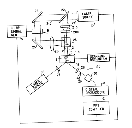
FIG. 16 shows an embodiment of a material
evaluation mechanism according to the present invention
for evaluating the material in a non-contact and non-
destructive manner. A laser beam 21 emitted from the
laser source 13 is divided into two laser beam 2la and
21b by a half mirror 22. The laser beam 21a is allowed
lS to pass through a beam-diameter adjuster 20a, which is
an example of the power adjuster 20, and then allowed to
pass through the beam splitter 23 serving as the
collimator 15 and the beam irradiator 17, so as to be
applied to the surface 4 of the object 3 as the parallel
laser beams 1. The other laser beam 21b is, through a
mirror 24, made incident on an acoustic optical device M.
A chirp signal generator S is connected to the acoustic
optical device M so that the frequency of the laser beam
is modulated. The laser beam allowed to pass through
the acoustic optical device M is allowed to pass through
a mirror 25, a converging lens 26, and a beam splitter
23 serving as the focusing optics 16 and the beam
2 1 88705
- 25 -
irradiator 17, so as to be applied to the surface 4 of
the object 3 as the focusing laser beams 2. As a result,
the bulk acoustic waves 7 focusing to the focus point 8
are generated in the object 3.
The object 3 is provided with the scanning
mechanism 19 for moving the object 3 in the directions
of x and y. A control signal having the fre~uency which
is successively changed as shown in FIG. lO is supplied
from the chirp signal generator S to the acoustic
optical device M. Therefore, the bulk acoustic waves
can three-dimensionally be scanned in the object. As
described above, the chirp signal generator and the
acoustic optical device may be omitted from the
structure and the converging lens 26 and the object 3
may mechanically be moved to change the depth of the
focus point of the focusing laser beams 2 so as to
change the depth of the bulk acoustic waves.
The probe beam 10 emitted from the laser source 18
is, through the converging lens 27, applied to the rear
surface of the object 3. Reflected beam 11 from the
rear surface is detected and analyzed by a knife edge
analyzer 12a adapted to the principle of the knife edge
method and serving as an example of the analyzer 12.
The knife edge analyzer 12a comprises a converging lens
28, a knife edge 29, a photodiode 30, and a digital
oscilloscope 31. Reflected beam 11 from the object 3 is
processed such that either of the upper or lower portion
21 88705
- 26 -
of the spot of the reflected beam 11 is cut by the knife
edge 29. As a result, change in the reflection angle of
the reflected beam 11 occurring attributable to the
unevenness of the surface of the object and corre-
sponding to the bulk acoustic waves can be detected.Thus, the intensity of the bulk acoustic waves 7 can
accurately be performed. Note that the digital
oscilloscope 31 and the scanning mechanism 19 are
connected to an FFT (Fast Fourier Transform) computer C.
Note that the computer C performs analysis and
calculations of a defects in the material and the
characteristics of the material.
A .esult of an actual operation of the embodiment
shown in FIG. 16 will now be described. The radius of
the beam on the surface 4 of the object 3 was about
0.5 tmm] and the object 3 was a steel plate having a
thickness of 1 [mm]. In this case, the specific
acoustic speed (the longitudinal waves) of the steel
plate was about 4700 m/second. Laser beams polarized
completely and having a wavelength of 532 [nm] was
oscillated by a second harmonic of a Q switch Nd-YAG
pulse laser, and the pulse width of the laser beam was
made to be 50 nsec. The oscillated laser beam was
divided to pass through two passages by the beam
splitter. The frequency of the laser beam 21b of the
two laser beams 2la and 2lb was modulated by the
acoustic optical device M by 100 MHz. To make the two
- 2 1 88705
-- 27 --
laser beams 21a and 21b to completely interfere with
each other, the beam-diameter adjuster 20a or the like
was used to adjust the energy density of the parallel
laser beams 21a and the focused laser beams 21b on the
surface of the object to be the same.
The intensity of the bulk acoustic waves 7 detected
by the analyzer 12 is shown in FIG. 17. FIG. 17 has an
axis of abscissa standing for x coordinates and an axis
of ordinate standing for the intensities (the relative
values) of the bulk acoustic waves when the focus point
of the focusing laser beam is scanned in the x direction
(surface direction) of the object 3. As shown in
FIG. 17, d fact that the bulk acoustic waves was reached
the rear surface of the object immediately below the
lS focus point 8 was detected by the knife edge method.
Although the embodiment shown in FIG. 16 has been
described about the knife edge analyzer 12a which serves
as the analyzer 12, a heterodyne interferometer method
or a Fabry-Pérot interferometer method may be employed.
FIG. 18 shows the principle structure of a
heterodyne-method interferometer 12b. A laser beam
having frequency F is emitted from a laser source 33,
and then the laser beam is branched into two sections by
a half mirror 34. The frequency of either of the two
reflected beams is, by an acoustic optical device 32,
modulated into a frequency of F + f and the modulated
beam is irradiated on the surface of the object 3. As
- 28 - 2188 ~05
described above, a small displacement 35 is formed on
the surface of the object 3 attributable to the bulk
acoustic waves so that the laser beam having the
frequency of F ~ f is reflected by the portion of the
S small displacement 35.
The reflected beam and the beam allowed to pass
through the half mirror 34 is made incident upon a half
mirror 36, and then mixed by a half mirror 36. However,
the laser beams respectively having the frequency of F
and that of F + f interfere with each other, thus
resulting in beat being generated. A beam reflected by
the half mirror 36 is converted into an electric signal
by a photodiode 37, and then observed by an oscilloscope
38 so that the "change in the phase of the beat" is
detected.
Assuming that the displacement on the surface of
the object corresponds to 1/4 of the wavelength of the
laser beam, also the phase of the "beat" generated
attributable to the interference between the reflected
laser beam and the laser beam directly propagated from
the half mirror 34 to the half mirror 36 is shifted by
a distance corresponding to half of the wavelength of
the "beat". Since the ~beat~' signal is a signal having
a low frequency similar to that the modulation frequency,
change in the phase of the "beat" can easily be observed
by an oscilloscope 38.
As described above, the heterodyne method enables
~188~05
- 29 -
the change in the phase of the beat to be measured to
observe slight displacement similar to the wavelength of t
light on the surface.
FIG. 19 shows an interferometer 12c adapted to the
Fabry-Pérot method in which an interferometer comprising
semitransparent mirrors 39 and 40 for extracting and
transmitting a beam having a specific frequency (a
wavelength) is used. A beam emitted from a laser source
41 and having a frequency of F is reflected by a
displaced portion 42 (which is vibrated with frequency
f) on the surface of the object 3. The frequency F of
the reflected beam is, attributable to the Doppler
effect, changed to frequency F'. The interferometer f
comprises the mirrors 39 and 40 in such a manner that
only a beam except a beam having the frequency of F, for
example, F' is extracted. As a result, the beam having
the frequency of F' is made incident upon a photodiode
43 so as to be converted into an electric signal. The
electric signal is observed by an oscilloscope 44 so
that displacement generated in the object 3 is observe.
FIG. 20 shows another embodiment of a material
evaluation mechanism which is a modification of FIG. 16.
In FIG. 16, transmission acoustic waves passing the
defect are detected by the probe laser beam. In FIG. 20,
acoustic waves reflected by a defect 100 are detected by
the probe laser beam. Other portions are the same as
those of FIG. 16.
21 88705
- 30 -
As described above, according to this embodiment,
the following effects can be obtained.
(1) Coherent parallel laser beams and focusing
laser beams having different frequencies are irradiated
onto the surface of an object to form interference
fringes propagating from outside to the inside portion.
Under condition that the propagation speed of the
interference fringes is higher than the specific
acoustic speed of the object, bulk acoustic waves
focusing to a predetermined point in the object can
easily be excited.
(2) By applying a probe beam and by scanning the
object, a defect, the material and characteristics of
an arbitrary small region in an object can accurately be
detected by a non-contact and non-destructive manner.
Therefore, the material can be evaluated more accurately
and efficiently with high spatial resolution as compared
with the conventional technology.
(3) By shifting the focal position of the focusing
laser beams or by changing the frequency difference
between the parallel laser beams and the focusing laser
beams, the depth in the small region of the object to
which the bulk acoustic waves are focused can be
adjusted successively or in a stepped manner. Therefore,
a flaw in the inside portion can quickly be detected.
The present invention is not limited to the above-
mentioned embodiment and a variety of modifications may
21 88705
- 31 -
be permitted. Although the structure has been described
in which the interference fringes 5 having the intervals
which are successively changed (the intervals are
increased in the direction toward the inside portion~
are formed, the foregoing structure is realized because
the spherical wave having a spherical phase surface is
employed as the focusing laser beams 2. When a focusing
laser beams having a required aspherical phase is
employed, concentric interference fringes S' having the
same intervals as shown in FIG. 21 are formed. Bulk
acoustic waves 7' generated in accordance with the
distortion distribution generated on the surface 4 of
the object 3 attributable to the interference fringes S'
are focused to focus point 8a in the form of a vertical
straight line, as shown in FIG. 21. As a result, the
characteristics of the material in the direction of the
depth can be inspected by one laser irradiation. Thus,
the labor for evaluating the material can be saved.
Note that the resolution in the direction of the depth
of the material can be obtained depending upon the
difference in the detection time of a signal of the
reflected acoustic waves. The interval h of the
interference fringes 5' must have the following
relation:
V < h-f
As described above, the shape of the focusing laser
beams is changed so that interference fringes having
- 32 _ 2 1 88705
an arbitrary shape are formed and the focus position of
the bulk acoustic waves is arbitrarily set. If focusing
laser beams having a cylindrical phase surface are
employed, bulk acoustic waves can be focused on a
horizontal straight line.
In the above description, it is assumed that the
object 3 is an isotropic object. The present invention
can be applied to an anisotropic object. In the case of
the anisotropic material, the specific acoustic speed of
the material is, however, different owning to the
direction or angle of incidence of the laser beam.
Therefore, the pattern of the interference fringes
focused in the object by the excited acoustic wave is
not formed into the concentric circles. By distorting
the focusing laser beams or the parallel laser beams,
the shape of the interference fringes can be controlled
to excite required bulk acoustic waves.
FIG. 22 shows a distorted phase distribution formed
on the surface of an object by acoustic waves radiated
from a point S in an anisotropic object. It is assumed
that acoustic waves having a frequency f is excited at
a point S in the anisotropic object 4 and acoustic waves
having a phase distribution as shown in FIG. 22
transmitted to the surface of the object 4. Coherent
parallel laser beams and focusing laser beams having
different frequencies for generating a distortion
distribution which is the same or approximate a phase
2 t 88705
._
- 33 -
distribution of the acoustic waves are applied to the
surface of an object so that interference fringes
propagating from outside toward the inside portion is
formed. At a surface of the object, the photo-thermal
operation of the interference fringes enables distortion
having the same phase distribution as the phase distri-
bution of the acoustic wave shown in FIG. 22 to be
formed. As a result, bulk acoustic waves focusing
toward the point S in the object can be excited.
FIG. 23 shows another example of the anisotropic phase
distribution formed on the surface of an anisotropic
object attributable to acoustic waves generated in the
anisotropic object.
As described above, according to the present
invention, the following effects can be obtained.
(1) Coherent parallel laser beams and focusing
laser beams having different frequencies are applied to
the surface of an object to form interference fringes
propagating from outside to the inside portion. Under
condition that the propagation speed of the interference
fringes is higher than the specific acoustlc speed of
the object, bulk acoustic waves focusing to a predeter-
mined point in the object can easily be excited. The
bulk acoustic waves can be employed in an operation in
which the operation is preferably performed while
vibrating the workpiece, for example, a process for
manufacturing a semiconductor as well as inspection and
21 88705
- 34 -
evaluation of an object.
(2) The bulk acoustic waves can easily be focused
to a specific position in an object attributable to the
shape of the focusing laser beams. According to the
circumstances, the bulk acoustic waves can simultane-
ously be focused to a multiplicity of focus positions
along a straight line.
t3) By applying a probe beam and by scanning the
object, a defect, the material and characteristics of an
arbitrary small region in an object can accurately be
detected by a non-contact and non-destructive manner.
Therefore, the material can be evaluated more accurately
and efficiently with high spatial resolution as compared
with the conventional technique.
(4) By shifting the focal position of the focusing
laser beams or by changing the frequency difference
between the parallel laser beams and the focusing laser
beams, the depth in the small region of the object to
which the bulk acoustic waves are focused can be
adjusted successively or in a stepped manner. Therefore,
a flaw in the inside portion can quickly be detected.
(5) Even if an object has anisotropic
characteristic, the structure, in which an assumption is
made that the acoustic waves are generated in one point
in the object and calculations are performed in
consideration of the anisotropic characteristic to
estimate the phase distribution of the acoustic waves on
- 35 -
the surface of the object so as to generate interference
fringes corresponding to the phase distribution, enables
bulk acoustic waves focusing to the foregoing point to
be excited. As a result, even an anisotropic object can
S similarly be inspected.