Note: Descriptions are shown in the official language in which they were submitted.
. WO 95129335 218 8 7 5 3 p~/AU95I00239
TT~T'T'~'
IC ENGINE FUEL SUPPLY SYSTEM
MELD OF THE INVENTION
The present invention relates to an IC engine fuel supply
system having a vapourising/pollution reducing carburettor
particularly, although not exclusively, envisaged for use in
the supply of liquid fuels into internal combustion (IC)
engines in a vapourised form for reducing the quality of liquid
fuel required for a given amount of energy output from the IC
engine and for reducing the quantity of pollution produced by
the IC engine in producing that energy.
'BACKGROUND OF THE INVENTION
In the field of IC engines is it known to use carburettors
to meter liquid fuel into the IC engine for combustion in a
combustion chamber. The carburettor causes a mixing of the
liquid fuel with air for said combustion.
Prior art carburettors have focussed on the issue of the
nature of the mixture of the liquid fuel with the air, for
example as shown in US Patents 1,358,876 (Richardson),
1,387,420 (Lambard) and 1,464,333 (Pembroke).
The actual explosion of the fuel/air mixture in the
combustion chamber does not occur until the fuel vaporises.
This vapourisation is achieved by the residual heat of the
combustion chamber and the pressure of the compression stroke
of the piston in the cylinder of the engine corresponding to
the combustion chamber. As a result of-this there is a delay
between ignition of the fuel/air mixture and actual explosion
to drive the piston down in the cylinder. Accordingly, the
ignition of the fuel/air mixture must be initiated before the
compression stroke of the piston is complete. Typically, the
ignition occurs at between 6 to 10 before the piston reaches
"top dead centre" (which signifies completion of the
compression stroke). During the time after ignition and prior
to explosion the liquid fuel is gradually vapourised as a flame
front from a spark plug travels through the combustion chamber.
When sufficient of the liquid fuel has vapourised the fuel/air
mixture reaches an accelerated rate of combustion known as an
explosion. The timing of the ignition is set so that the
explosion occurs when the piston has reached top dead centre
2188753
R'O 95129335 PCT/AU95100239
- 2 -
and hence maximum down force is imparted to the piston and
hence is applied to the motive force of the IC engine.
However, a disadvantage of this is that some of the fuel
in the combustion chamber remains in a liquid state even
through the explosion and is subsequently exhausted to the
atmosphere. This leads to a reduction in the efficiency of the
use of the fuel and an increase in the pollution created by the
IC engine.
The efficiency of the use of the fuel can be increased by
l0 vapourising the fuel before -it enters into the combustion
chamber. Then all of the vapourised fuel can be exploded and
be applied to the motive force of the IC engine. Also, as a
consequence of the more complete burn there. is less pollution
produced.
Attempts have been made in the past to vaporise the fuel
prior to its entry into the carburettor by heating the fuel
with heated gases from the IC engine exhaust, as exemplified
by POGUE in US2,026,798. A disadvantage of -these types of
systems is that they are relatively complex, and difficult and
expensive to manufacture.
My invention concerns how to achieve vapourisation prior
to introduction into the combustion chamber without the use of
heat.
OF THE INVEN
Therefore it is an object of the present invention to
provide an IC engine fuel supply system having a
vapourising/pollution reducing carburettor for vapourising fuel
prior to its entry into the IC engine.
In accordance with one aspect of the present invention
there is provided an IC engine fuel supply system having a
vapourising/pollution reducing carburettor for an IC engine,
the vapourising/pollution reducing carburettor comprising:
a vapourisation chamber having a mantle means for ,
suspending fuel within vapourisation chamber, and a mesh means
associated with the mantle means such that the fuel must flow ,
through the mesh means when leaving the mantle means;
a fuel intake means located in operative association with
the vapourisation chamber for metering an amount of the fuel
from a fuel supply to the mantle means for suspension in the
WO 95129335 ~ PCTIAU95100239
- 3 -
vapourisation chamber;
an air intake means located down stream of the
vapourisation chamber, the air intake means having a valve
means for regulating the amount of air flowing through the
vapourisation chamber in accordance with the pressure in an
intake manifold of the IC engine, the air intake means being
disposed-so that air is directed through the mantle means for
vapourising said fuel suspended in the said mantle means;
a fuel scavenger means in operative association with the
mantle means for removing excess and non-vapourised fuel from
the mantle means and from the vapourisation means and returning
said fuel to the fuel supply; and,
a conduit means for introducing vapours from the
vapourisation chamber into an intake manifold of the IC engine.
BRIEF DESCRIPTION OF THE DRAWINGS
An exemplary embodiment of the present invention will now
be described with reference to the accompanying drawings in
which:-
Figure 1 is a schematic representation of an IC engine
fuel supply system incorporating a vapourising/pollution
reducing carburettor both in accordance with the present
invention;
Figure 2A is cress-sectional side view of a canister of
the carburettor of Figure 1 and including a vapourisation
chamber and a mixing chamber;
Figure 2B is a cross-sectional side view of a valve base
plate of the carburettor of Figure 1;
Figure 2C is a cross-sectional side view of sealing plate
of the carburettor of Figure 1;
Figure 2D is a cross-sectional side view of a valve of the
carburettor of Figure 1;
Figure 2E is a cross-sectional side view of vapour outlet
chamber of the carburettor of Figure 1;
Figures 3A and 3B are respectively an upper plan view and
a lower plan view of the valve base plate of Figure 2B;
Figures 4A to 4C are respectively an exploded cross-
sectional side view, a front end view and a rear end view of
a fuel supply valve of the IC engine fuel supply system of
Figure 1.
2188753
WO 95129335 PCTIAU95100239
- 4 -
DETAILED DESCRIPTION OF THE PREFERRED EMBODIMENTfS)
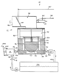
In Figure 1 there is shown an IC engine fuel supply system
comprising a carburettor 12, a fuel supply valve 14, a
pressure reduction valve i6, fuel pump 18, a fuel tank 2o and
5 a scavenger pump 22 for use in association with an IC engine. '
The fuel supply valve 14 connects the carburettor 12 to the
fuel tank 20 via the pressure reduction valve 16, and the '
scavenger pump 22 provides return path for unused fuel from the
carburettor 12 back to the fuel tank 20.
10 The carburettor 12 comprises a vapourisation chamber 30,
a mixing chamber 32 and a vapour outlet chamber 34. The
vapourisation chamber 30 is in part defined within a canister
40. The vapourisation chamber 30 comprises a valve base plate
42, sealing plate 44, a ball valve 46, a foam mantle 48 and a
perforated annular washer 50. The valve base plate 42 sits
upon the sealing plate 44 which is attached to an air intake
conduit (not shown - as are commonly used in present day motor
cars). The ball valve 46 seals upon the valve base plate 42
and is housed inside the foam mantle 48. Whilst, the
2o perforated annular washer 5o sits upon the foam mantle 48.
As shown in more detail in Figure 2A the canister 40 is
substantially cylindrical and has an lower end 60 and an upper
end 62 provided with an inwardly disposed annular lip 64 for
attachment to the vapour outlet chamber 34. A lower portion
of the canister 40 defines a part of the vapourisation chamber
30.
As shown in Figure 2B the valve base plate 42 is generally
circular when viewed in plan and substantially rectangular when
viewed one its side. The base plate 42 has a body 70 with a
central venturi inlet 72 which has a valve seat 74 in its upper
edge. The valve seat 74 is disposed to receive the ball valve
46. The valve seat 74 is typically at an angle of 45° to the
axis of the venturi inlet 72 so as to direct air out of the
venturi inlet 72 at an angle of about 45° and hence into the
foam mantle 48 as described in more detail hereinafter.
The valve base plate 42 also has a first annular channel
76 extending substantially entirely about the body 70 proximate
its outer edge 78. The first annular channel 76 is in fluidic
communication with a fuel inlet 80 located in the outer edge
288753
WO 95129335 PCT/AU95100239
- 5 -
78 of the body. Also, the first annular channel 76 opens into
a lower face 81 of the body 70 and has a plurality of
relatively small holes 82 connecting it to an upper face 84 of
the body 70 so that fluid can flow from the fuel inlet 80,
around the first channel 76 and through the holes 82 to the
upper face 84 and hence to the foam mantle 48.
The valve base plate 42 also has a second annular channel
86 whichis substantially coaxial with the first annular
channel 76 and located between the first annular channel 76 and
to the venturi inlet 72. The second annular channel 86 also opens
into the lower face 81 and has relatively small holes 88
connecting it to the upper face 84. The body 70 also has a
fuel outlet 90 located in the outer edge 78 of the body 70
typically opposite from the fuel inlet 80. The second annular
channel 86 is in fluidic communication with the fuel outlet 90
so that fuel can flow from the upper face 84, through the holes
88, into the second annular channel 86 and to the fuel outlet
90.
The holes 82 have a diameter of between 1 mm and 3 mm
depending upon the fuel requirements of the IC engine. For
example, a 4 litre IC engine typically requires holes with
a
diameter of about 2 mm. Preferably, the diameter of the holes
82 is greater than the mesh size of a fuel filter of the IC
engine so that any detritus material Which is not caught by
the
fuel filter will not block the holes 82.
The holes 88 have a diameter which is greater than the
holes 82 so that the excess fuel can be easily scavenged back
to the fuel tank 20. The diameter of the holes 88 is typically
between 2 mm and 5 mm, such as, for example, about 3 mm in
the
case of a 4 litre IC engine.
As shown in Figure 2C the sealing plate 44 is circular
when viewed in plan and substantially rectangular when viewed
from the side. The sealing plate 44 has a diameter which is
substantially the same as that of the body 70 of the valve
base
plate 42. The sealing plate 44 has a central hole 100 which
is intended to be coaxial with the venturi inlet 72 of the
valve base plate 42. The hole 100 is intended to be larger
than the venturi inlet 72 so as to not affect the flow of air
into the venturi inlet 72. The sealing plate 44 is fixed to
2188753
W0 95129335 PCTIAU95I00239
6
the lower face 81 ofthe valve base plate 42 so as to close off
the first and second channels 76 and 86 to form two annular
conduits with the valve base plate 42. Typically, the sealing
plate 44 is attached to an air duct for conveying a stream of
air into the carburettor 12.
As shown in Figure 2D the ball valve 46 comprises a top
plate 11o, a plurality of pasts 112 (such as 4 posts 112), a '
valve member 114, a guide rod 116 and a compression spring 118.
The posts 112 are threadedly engaged with threadedmounting
holes 120 in the upper face 84 of the valve base plate 42 at
one end and secured to the top plate 1i0 at their other end.
The guide rod 116 is located in a hole 122 in the top plate 110
so as to allow the valve member 114 to rise and fall with
respect to the top plate against the downward force of the
spring 118 which is located about the guide rod 116 between the
top plate 110 and the valve member 114. The force of the
spring 118 is large enough to cause the valve member 114 to
seat against the valve seat 74 and to allow the valve member
114 to rise up off the valve seat 74 to introduce air into the
carburettor when low pressure is induced in the carburettor by
the intake stroke of the IC engine. The valve member 114 has
a head 124 which is shaped to seat against the valve seat 74.
For this purpose the head 124 is typically hemispherical. The
top plate 110 is typically square when viewed in plan and is
dimensioned to fit within the foam mantle 48 so that air
passing throughthe venturi inlet 72 tends to-flow through the
foam mantle 48. The foam mantle 48 and the ball- valve 46
define the vapourisation chamber 30.
As shown in Figure 2A the foam mantle 48 is located within
the lower reaches of the canister 4o with the perforated
annular washer seated on top of -it. The foam mantle 48 is in
the shape of an annular ring. The foam mantle 48 is made from
foamed plastics materials which have a reticulated (open pore)
structure which is porous to liquids and allows liquids to flow
through it whilst retaining a fine film of the-liquid suspended
in it. For example, the foamed plastics material could be a
reticulated polyurethane foamed plastic such as sold under the
registered Trade Mark MERACELL. The lower end 60 of- the
canister 40 is secured to the valve base plate 42 with the foam
218875
R'O 95!29335
PCTIAU95100239
_ 7 _
mantle 48 firmly in contiguous contact with the upper face 84
of the valve base plate 42 over the holes_82 and 88.
A wire cage 130 is located between the lip 64 and the
perforated annular washer 5o for defining the mixing chamber
32. Typically, the cage 130 is made from aluminium, although
other metals or even plastics materials could be used provided
they are resistant to attack by hydrocarbon fuels and do not
react with other materials in the carburettor 12. The
perforated annular washer 50 typically has a 50% perforation
rate. That is the perforated annular-washer 50 is 50% holes
by area and 50% solid material by area in the region of its
annulus. Typically, the holes have a diameter of between 0.5
mm and 2.0 mm, such as, for example, about 1.0 mm.
The canister 40 has a height which varies according to the
capacity of the IC engine which it is used with. Typically,
for a 2 litre engine the canister 40 has a height of about 150
mm. The height of the vapourisation chamber 3o is the canister
4o is to kept relatively constant at about loo mm and the
height of the mixing chamber 32 is varied for IC engines of
differing capacities. Hence, in relation to the 2 litre IC
engine the mixing chamber 32 has a height of about 50 mm (and
the canister 40 a height of about 150 mm). In the event that
the height is less than this complete vapourisation of fuel
is
not achieved. In the event that the height is more than this
the extra capacity of the mixing chamber is not detrimental
to
the vapourisation of the fuel. For an IC engine with a
capacity of about 6 litres it is intended that the canister
have a height of about 200 mm. In relation to relatively small
capacity IC engines, such as in motor cycles, it is envisaged
30 that the canister 40 have an overall height of about 120 mm
and
in relation to relatively large IC engines, such as in trucks,
it is envisaged that the canister 40 have a diameter of about
240 mm. It is intended that the canister by mounted onto the
fire wall of the engine bay of a motor vehicle. This is
35 considered necessary since the canister 40 alone is higher and
wider than most conventional carburettors.
The diameter of the canister 40 is dictated by the
diameter of the venturi inlet 72, which is in turn dictated
by
the capacity of the IC engine. In relation to the 2 litre IC
288753
WO 95129335 PCTlAU95/0U239
- 8 -
engine example the venturi inlet 72 is about 49 mm. This is
the value determined by the manufacturer of the IC engine for
the venturi size in its engine. The diameter of the canister
40 is preferably between 2.5 and 3.5 times the diameter of the
venturi inlet 72. Hence, for the 2 litre IC engine example the
canister 40 preferably has a diameter of between about 120 mm
and 170 mm. If the diameter of the canister-40 is less than
2.5 time the diameter of the venturi inlet 72 then the
carburettor 12 will draw too much fuel for the amount of air
flowing through the venturi inlet 72. And if-the diameter of
the canister 40 is greater than 3.5 times the diameter of the
venturi inlet 72 then the IC engine will experience fuel
starvation and a loss in throttle response since insufficient
fuel will flow for the amount of air flowing through the
venturi inlet 72.
As shown in Figure 2E the vapour outlet chamber 34 is
defined by an elbow shaped duct 140 which has a flange 142 for
fixture to the lip 64 of the canister 40. The duct 140 has a
butterfly valve 144 located proximate its mouth 146. The
butterfly valve 144 is controlled by an accelerator cable 147.
The vapour outlet -chamber 34 has an inlet 148 which overlies
a hole 150 in the upper end 62 of he canister 40. The vapour
outlet-chamber 34, from its inlet 148 to the mouth 146, has a
diameter which is greater the diameter of the venturi inlet 72.
This is required so that the vapour outlet chamber 34 does not
cause a restriction in the flow of the air from the venturi
inlet 72 to the mouth 146. The mouth 146 is typically
connected to the inlet manifold of the IC engine by a flexible
conduit.
The vapour outlet chamber 34 also has a supplementary air
intake 152 with a butterfly valve 154 controlled by a vacuum
unit 156 connected via a control rod 158 and a link 160 to a
lever arm 162 attached to a pivot of the butterfly valve 154.
The vacuum unit 156 is connected to the intake manifold of the
IC engine (in much the same way as an ignition timing advance .
for a conventional carburettor system) by a vacuum line 164 so
that in the event that the vacuum in the intake manifold
becomes sufficiently large the butterfly valve 154 starts to
open to allow more air into the carburettor so as to allow the
2188753
WO 95!29335
PCTIAU95100239
_ g _
IC engine to breathe better when under load.
As shown in Figures 4A to 4C the fuel supply valve 14 has
a body 170, an end cap 172, a head 174, an accelerator jet
176,
a diaphragm 178 and an idle jet 180. The body 170 has a
central hole 182 which receives the accelerator jet 176. The
diaphragm 178 is sandwiched between the body 170 and the end
cap 172 and is attached to a threaded end 183 of the
accelerator jet 176 by nuts 184. One end of the hole 182
terminates in a recess 186 which is dimensioned to allow
l0 movement of the aesembly of the accelerator jet 176, the
diaphragm 178 and the nuts 184 in it as the accelerator jet
176
moves axially in, the hole 182. The end cap 172 has an aperture
188 also for allowing the said movement of the said assembly.
The head 174 has a conduit 190 extending through it and
with a jet seat 192 intermediate of its length. The valve seat
192 is shaped to receive a pointed end 194 of the accelerator
jet 176. The head 174 also has a fuel inlet 196 and a fuel
outlet 198. The fuel inlet 196 is connected to the conduit
190
by a conduit 200 upstream of the valve seat 192 so that the
pointed end 194 of the accelerator jet 176 can interrupt the
flow of fuel from the fuel inlet 196 to the fuel outlet 198.
The fuel outlet 198 is in fluidic communication with the
conduit 190 downstream of the jet seat 192. The head 174 also
has a bleed conduit 202 connected from the conduit 200 to the
fuel outlet 198. The bleed conduit 202 has a head 204 of the
idle jet 180 located in it so that the idle jet 180 can adjust
the rate of flow of fuel along the bleed conduit 202 when the
accelerator jet 176 is seated against the jet seat 192.
As shown in Figure 1 a throttle lever 206 pivotably
attached to the threaded end 183 of the accelerator jet 176
and
to the end cap 172. The throttle lever 206 is attached to a
throttle cable 208 so that pulling of the throttle cable gives
a proportionate (but smaller) movement of the accelerator jet
176.
Also, as shown in Figure 1 the fuel outlet 198 is
connected by a hose 210 to the fuel inlet 80 of the valve base
plate 42. Another hose 212 connects the fuel inlet 196 to the
low pressure side of the pressure reduction valve 16. The high
pressure side of the pressure reduction valve 16 is connected
2188753
W0 95129335 PGTIAU95100239
- 10 -
to the fuel pump by a hose 214 and hence to the fuel tank 20.
Typically, the pressure reduction valve 16 reduces the
pressure of fuel from the fuel-pump 18 to between 14 kPa to 36
kPa, such as about 24 kPa. The pressure reduction depends upon
the typical load which the IC engine experiences. '
The fuel outlet 90 of the valve base plate 42 is connected
by a hose 220 to the scavenger pump 22. A further hose 222 '
connects the scavenger pump 22 to the fuel tank 20 so that fuel
scavenged from the carburettor 12 can be returned to the fuel
tank 20 for later use. The scavenger pump 22 typically
operates at a pressure of about 90 kPa, although this is not
critical~provided that it exceeds the pressure of the fuel at
the downstream end of the pressure reduction valve 14.
In use, the canister 40 carburettor 12 is attached to the
fire wall of the engine bay of a vehicle. The pressure
reduction valve 16 is attached to the hose 214 from the fuel
pump 18, the hose 222 is connected from the scavenger pump 22
to the fuel tank 20, the mouth of the vapour outlet chamber 34
is connected by a conduit to the intake manifold of the IC
engine, the accelerator cable 147 is connected to the butterfly
valve 144, the vacuum line is connected to the vacuum unit 156
and the throttle cable 208 is connected to the throttle lever
206.
When the IC engine is at idle fuel flows from the fuel
tank 20 by force of the fuel pump 18, through the pressure
reduction valve 16 to the fuel supply valve 14. The fuel
enters the fuel inlet 196 of the fuel supply valve 14, flows
along the bleed-conduit 202 passed the idle jet 180 and to the
fuel outlet 198. The rate of flow of the fuel-during idle is
set by the position of the idle jet 180 in its threaded
engagement with the head 174 of the fuel supply valve 14.
During non-idle operation of the IC engine the throttle
cable 208 is pulled to pivot the throttle lever 206 and hence
relieve the accelerator jet 176 from the jet seat 192. This
allows fuel to flow along the conduit 200, passed the jet seat
192 and to the fuel outlet 198. The rate of flow of fuel
through the fuel supply valve 14 now depends upon the angular
position of the throttle lever 206 and hence the amount that
the pointed head 194 of the accelerator jet 176 is displaced
. WO 95129335 ~ ~ PCTIAU95100239
- 11 -
from the jet seat-192.
In both of the above cases the fuel flows from the fuel
outlet 198 along the hose to the fuel inlet 80 of the valve
base plate 42. There the fuel enters the first channel 76 and
flows about it, filling the channel 76 and rising up the holes
82 to the foam mantle 4B.- By virtue of the porosity of the
foam mantle 48 the fuel is absorbed into the foam mantle 48.
The vacuum created in the intake manifold of the IC engine
causes a low pressure region to develop in the vapourisation
chamber 30 about the valve member 114. This causes the valve
member 114 to be drawn upwardly against the returning force of
the spring 118. Consequently air is drawn in through the
venturi inlet 72. By virtue of the angle of the valve seat 74
and the position of the valve member 114 the air enters the
vapourisation chamber 30 at an angle of about 45° to the axis
of the chamber 30 and enters into the foam mantle 48. The air
is drawn, by the low pressure in the intake manifold, up
through the foam mantle 48 and out of the perforated annular
washer 50. As the air is drawn up through the foam mantle 48
the fuel suspended in the porous cells of the foam mantle 48
are bombarded with the air particles which causes the fuel to
become a vapour.
The vapour leaves the vapourisation chamber 3o through the
perforations in the washer 5o and through a centre of the
washer about the top plate 110 of the ball valve 46. The
vapourised fuel and the air mix in the mixing chamber 32 and
under the influence of the lower pressure are drawn into the
vapour outlet chamber 34. The amount of influence which the
lower pressure in the intake manifold has on the flow of air
through the carburettor 12 depends in part on the angular
position of the butterfly valve 144 in the mouth 146 of the
vapour outlet chamber 34 so that as the angle increases more
vapourised fuel mixed in air is drawn through the carburettor
12.
In the event that the low pressure in the intake manifold
continues to rise (indicating a large load on the IC engine)
the vacuum unit 156 operates to pivot the butterfly valve 154
to allow more air into the vapour outlet chamber 34 from the
supplementary air intake 152.
2188753
WO 95129335 , PCTIAU95100239
- 12 -
When the demand for fuel reduces excess fuel is drawn back
down onto the upper face 84 of the valve base plate 42 by the
scavenger pump 22 creating a lower pressure region in the
second channel 86 and hence in the holes 88. The fuel so
scavenged is pumped by the scavenger pump 22 back to the fuel
tank 20 for later use.
I have discovered that in the exemplary embodiment the '
angle- of the valve seat 74 for the ball valve 46 is quite
critical to the efficiency with th fuel is vapourised. That
l0 is the angle of the valve seat 74 must be about 45°. However,
if the fuel is injected downwardly (by an injection plate in
the form of the valve base plate 42 without the second channel
86) into the foam mantle 48 at its upper end and the fuel is
scavenged at the lower end of the foam mantle 48 then the angle
need not be 45°. In this situation the angle of the valve seat
74 is no longer of special significance. This occurs since in
this situation the injection plate controls the updraught of
fuel through the foam mantle 48.
i have discovered that applying the IC engine fuel system
10 of the present invention to an old model 6 cylinder motor
car reduces its fuel consumption from about 13 litres/lo0 kms
(20 miles per gallon) to about 2.6 litres/100 kms (110 miles
per gallon). Simultaneously, since there is a much more
complete burn of the fuel there is a great reduction in the
pollution produced.
I have also discovered that since the fuel reaches the IC
engine already vapourised (and vapourisation does not have to
occur during the combustion process) the timing of the ignition
of the IC engine can be changes from between 6° to l0° before
top dead centre to about 0.5° before top dead centre.
The IC engine fuel supply system 10 of the -present
invention has the advantage that it provides easy and efficient
vapourisation of fuel, the result of which is a vast
improvement in fuel efficiency and a considerable reduction in
pollution. Hence, conventional anti-pollution equipment used ,
on present day cars can be omitted, thus saving on the cost of
the vehicle. Also, by the use of the scavenger second channel
86 and the scavenger pump excess fuel is returned for reuse
which improves the efficiency of the system 10. Further, since
218873
~ WO 95129335 PCT/AU95/00239
- I3 -
less fuel is used there is less wear in the engine and the
engine operates at a lower temperature. Effectively, the
system converts a 4 stroke engine into a 3 stroke engine since
the timing of the engine can be much reduced. Still further,
the system 10 increase the throttle response of the IC engine.
Modifications and variations such as would be apparent to
a skill addressee are considered within the scope of the
present invention.