Note: Descriptions are shown in the official language in which they were submitted.
~ WO95/29811 21 89024 ~ S70
--1--
LaMINATION PROCE88 FOR C~
Ba~h~L ~ u--d of the Invention
5 Field of the Invention
This invention relates to preparing laminates in
which a coating i8 sandwiched between two substrates.
Descrit~tion of the Related Art
Laminated :.LLu~;LuLes in which a polymerizable
10 coating is sandwiched between two substrates are known.
It is desirable to maintain the 1-h; rl~n~cc of a coating
laid down on the substrates during lamination. It is
further desirable to avoid air entrainment during
lamination; such entrainment causes bubbles to develop
15 in the laminate :-LL ue -uLè. In addition, during
construction of multi-layer ~LL~.LuLes, it is desirable
to minimize inter-layer mixing.
~31m~ry of the Invention
In general, the invention features a method of
preparing a laminate that includes introducing a f irst
substrate having first and second surfaces and
supported at two or more points into a lamination zone
located between two of the support points . The f irst
25 substrate is ""r`~l.LJ~ 'L Led Llll~ u~ uL the lamination
zone. A second substrate, also having first and second
surfaces, is introduced into the lamination zone as
well. The second substrate passes around a lamination
bar to position the first surfaces of the two
30 substrates in a facing relatirnchip with each other.
At least one of the first surfaces i6 provided with a
coating. The lamination bar i8 de~Lèlj~.ed to laminate
the second substrate to the f irst substrate .
In preferred ~ ` -'i c, the 1-h;rknc-c5 of each of
35 the D~LLClLe8 is no greater than about 0. 635 mm (25
mils). The total thirl~n~-cc of the coating preferably
WO 9~/29811 2 1 8 9 ~ 2 4 P~~ .O 1170
ranges from about 0.0635 mm (0.25 mils) to about 6.35
mm (250 mils). One or both of the substrates may be
provided in the form of a continuous belt. Following
coating, the substrate can be d~l ~mi n~ted and re-used.
5 Il~ Jvt:~, a first surface of each substrate may be
provided with a coating.
The lamination bar may be a 601id bar or a hollow
tube. In the case of the latter, the tube may be an
air-~L t s~urized lamination tube adapted to create a
10 cushion of air between the second substrate and the
tube. The lamination bar is preferably adjusted to
depress the first substrate about 0.25 to about 12.7 mm
(10 to about 500 mils), preferably about 1. 27 - 3 . 8 mm
(50-150 mils), relative to the plane defined by the
15 first substrate and the two support points.
In certain preferred ~'i- Ls of the invention,
the coating applied to at least one of the f irst
surfzlces is polymerizable. In other preferred
f~mho~i- L:" the coating is subst~nt~Al ly solvent-free
20 (i.e., at least about 80% solids~ and is ~ore
preferably essentially solvent-free. In certain most
preferred Pmho~li- Ls, the coating is polymerizable and
solvent-f ree .
r 1 .,c of preferred polymerizable coatings
25 include (a) a mixture of liquid crystal and
polymerizable matrix reactants which upon
polymerization yields a polymer dispersed liquid
crystal film and (b) reactants which upon
polymerization yield an adhesive, e.g., a ~r ~S~ULe
30 sensitive adhesive.
The invention allows gentle pl ~ L of a
substrate onto the coated surface of another substrate,
thereby minimizing air entrainment at the point of
lamination and thus minimi~in~ bubble or pinhole
35 formation. The invention thus provides laminates
having a uniform polymerizable coating sandwiched
~ Wo95/~9811 2 1 89024 1 .,. ~s70
between two thin flexible substrates (one or both of
which may be subsequently removed) . The th; rknPcc of
the coating twhich i5 e6tablished prior to lamination
when the coating is applied to one or both of the
5 substrates) is not disturbed during the lamination
process. The invention is particularly useful in the
~L~ ~al~ion of optical quality films such as polymer
dispersed liquid crystal films in which the optical
properties of the device are sensitive to
10 irregularities such as th;~knPcc variations in the
optically responsive film. The invention is also
useful in the preparation of various adhesive
constructions, e.g., optical adhesives, transfer tapes,
foam-like adhesives, and c~ l;-r ~ UL~ sensitive
15 adhesive me_branes, as well as heat-activated films,
vibration damping materials, protective coatings, and
thin films. The invention is useful as well in the
~L~ ~aLcltion of "wet-on-wet" cu..~LL I. Lions involving
application of two or more polymerizable coatings
20 because inter-layer mixing is min;mi ~0~4.
Other features and advt.-~ of the invention
will be a~a~ t from the following description of the
prefer-_~d Pmho~li Ls thereof, ar from the claims.
Brief ~escriDtion of ,he Drawinas
The invention will be more fully understood with
reference to the following drawings in which:
Fig. 1 is a schematic drawing showing steps in the
lamination process according to the invention.
Fig. 2 is a schematic drawing showing steps in the
30 lamination process according to the invention,
~nr]~ in~ multiple coating operations.
Fig. 3 is a schematic drawing showing steps in the
lamination process according to the invention,
inrlllrling multiple lamination operations.
Fig. 4 is a schematic drawing showing steps in the
lamination process according to the inventlon in which
_ _ _ _ _ _
W095/29811 21 8~024 .~ l170 ~
--4--
one of the substrates is provided in the form of a
continuous belt.
Fig. 5 is a (;LU~ C s~_Lional view of an extrusion
die useful in preparing laminates according to the
5 invention.
Fig. 6 is an enlarged cross-sectional view of the
die of Fig. 5.
Fig. 7 is a ~:Lo55 ~C~innAl view of an alternative
configuration for a die useful in preparing laminates
10 according to the invention.
Descri~tion of the Preferred r ~
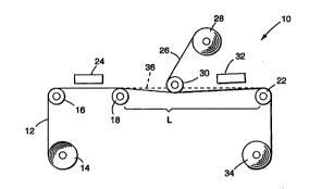
Ref erring to Fig . l, there is shown a lamination
apparatus 10 for preparing laminates in which, for
example, an essentially solvent-free (i.e., 100%
15 solids~ polymerizable coating is sandwiched between two
flexible substrates 12, 26. As shown in Fig. 1, a
first thin flexible substrate 12 (typically having a
thirknPcc no greater than about 0.64 mm (25 mils) ) is
~9~ cpPncPd from an unwind roll 14 . Examples of suitable
20 materials for substrate 12 include polymeric films such
as polyesters (e.g., polyethylene terephthalate),
polyethersulfones, polyimides, and polyuc~L2,u--ates. In
the case of devices for optical applications (e.g.,
light modulating devices~, substrate 12 preferably is
25 ~.~...c.~al~l.L. Substrate 12 may also include an
electrically conductive material, e.g., ~ IIL. ;11m,
indium tin oxide, tin oxide, stAinlPc~ steel, gold,
silver, copper, Alllmin--m, titanium, cadmium stannate,
transition metal oxides, and mixtures and alloys
30 thereof, to enable substrate 12 to function as an
electrode .
Substrate 12 is supported, for example, by a
series of three intermediate rolls 16, 18, and 22.
Roll 18 may be a driven backup if a die coating method
35 is used while roll 22 may be an idler roll. The area
between rolls 18 and 22 defines a lamination zone L.
~ W095/29811 2 ~ 89024 r~ "70
--5--
Substrate 12 is ~ r ~ed t~lLuL~ uu~ the lamination
zone .
Before entering the lamination zone, substrate 12
i5 provided with an essentially solvent-free
5 polymerizable coating which is deposited at a coating
station 24. Any type of polymerizable coating may be
deposited. Examples include miYtures of liquid crystal
and polymerizable matrix reactants which, upon exposure
to ultraviolet radiation, polymerize to form an
10 optically responsive PDLC film in which li~auid crystal
is dispersed throughout a polymer matrix. Examples of
suitable matrix reactants include mono-functional
(i.e., having one polymerizable group~ and multi-
functional ( i . e ., having two or more polymerizable
15 groups) reactants such as mono- and multi-functional
enes ( i . e., an "ene" is a reactant having a
poly -;7~hlP carbon-carbon double bond; e.g.,
acrylates, methacrylates, acrylamides, methacrylamides,
vinyl silane6, allyls, and vinyl ethers); thiols;
20 silicon hydrides; alcohols; epoxies; isocyanates;
amines; and/or combinations thereof.
Also suitable are reactants which upon
polymerization yield adhesives, e.g., ~Les ULe:
sensitive adhesives, foam-like adhesives, and cellular
25 yLe~uLe sensitive adhesive membranes. The reactants
may be thP~r-l ly or radiation cured. Examples include
alkyl acrylates and methacrylates, epoxies,
isocyanates, and combinations thereof.
Also suitable are reactants which upon
30 polymerization yield films or protective coatings
(e.g., acrylates, epoxies, vinyl ethers, and
combinations thereof ), as well as reactants that yield
vibration damping materials (e.g., acrylates). The
reactants may be ~hPrTA-lly or radiation cured.
The polymerizable coating may be deposited on
substrate 12 at coating station 24 by a wide variety of
WO9S/29811 2 1 890 4 P~ 'Cll70 ~
coating techniques. Examples include knife coating,
reverse roll coating, notched bar coating, gravure
coating, slide coating, curtain coating, spray coating,
extrusion coating, and other conventional coating
5 techniques. Where caliper control of the polymerizable
coating is important (e.g., in the pl~:paLc-tion of
optical quality f ilms), a precision coating die may be
used such as described in Vesley et al., PCT
International application No. (Attorney Docket
10 No. 50778PCT5A), entitled "Precision Coating Process
for Preparing Polymerizable Films" filed concurrently
with, and assigned to the same assignee as, the present
application .
Once substrate 12 has been coated with the
15 polymerizable coating, it is transported from coating
station 24 into the lamination zone located between
idler rolls 18 and 22. A second substrate 26 (which
may be the same material as substrate 12) is ~; cp~nce~
from an unwind roll 28 into the lamination zone as
20 well. Substrate 26 passes around a lamination bar 30,
causing the direction of the moving substrate to
change .
Lamination bar 30 i8 preferably an air-
~L.:s~usized, sintered metal, hollow tube typically
25 measuring 2.54 - 10.16 cm (1-4 inches) in diameter; the
~ir ~JL~Sc~UL~ delivered to bar 30 (typically about 1.4 -
4.5 bar) allows substrate 26 to ride on a cushion of
air as it pas_es around lamination bar 30. Lamination
bar 30 may also be in the form of a hollow tube
30 provided with slots or holes; such tubes are
particularly useful in the case of substrates requiring
relatively large turning radii . 8ar 3 0 may also be in
the form of an idler roll (which may be solid or
hollow), or in the form ~f a solid or hollow cylinder
35 that ~erves as a turning point for the substrate.
Preferably, bar 30 is close to roll 18.
~ Wo 95/29811 2 1 8 9 0 2 4 . ~~ r s IN
--7--
Lamination i8 accompliEihed by mechanically
depressing bar 30, thereby causing deflection of
substrate 12 below the plane indicated by dotted line
36 that it would normally follow as it passed between
5 rolls 18 ~nd 22. The eYtent of deflection is referred
to as "interference. " The interference is generally in
the range of about 0. 64 - 6. 35 mm (25-250 mils), and
preferably in the range 1.27 - 3.8 mm (50-150 mils).
The particular value for the intt L r~ ce is chosen
10 based upon the viscosity and fluid properties of the
polymerizable coating, web speed, and caliper of the
substrate. If the interference is not sufficiently
high, air entrainment may occur, resulting in pinhole
formation in the polymerized coating. On the other
15 hand, excessive interference can cause spreading of the
polymerizable coating, thereby reducing coating
th i ~ n~l::8 .
Following lamination, the resulting unpolymerized
sandwich is transported to a reaction station 32 where
20 it is eYposed, e.g., to heat, ultraviolet radiation,
visible radiation, or a combination thereof, as is
well-known in the art, to poIymerize the coating.
Reaction station 32 preferably is located in close
proximity to the coating zone and may U~IC - ~8 idler
25 roll 22. Preferably, the coating should be at least
partially polymerized bef ore reaching roll 22 to
prevent disturbing the caliper of the coating. The
resulting laminate may then be wound onto take-up roll
34 .
Referring to Fig. 2, multiple coatings may be
applied using several coating stations 24 and 40;
additional coating stations may be included as well.
The a-lvc.-.Lag~ of the present lamination in applying
multiple coatings is that inter-layer miYing of the
35 uncured coatings is minimi7 cl.
Wo9~29811 21 89024 ~ u~ 70
--8--
Referring to Fig. 3, more than two 6ubstrates may
be laminated togethPr through the inclusion of multiple
lamination zones. As shown in Fig. 3, the laminate
formed from sub6trates 12 and 26 is passed to a
5 reaction station 54 to polymerize the polymerizable
coating; alternatively, reaction station 54 may be
eliminated and a single reaction station 32 used to
polymerize all coatings. NeYt, a third substrate 48
rPn~Ptl from an unwind roll 50 is provided with a
10 polymerizable coating at coating station 56 and then
laminated to :.ul,~LL~te 26 in the lamination zone
defined by idler rolls 42 and 22 by means of lamination
roll 52. The multiple lamination zone Pmho,l; L shown
in Fig. 3 may be `- i nP~ with multiple coating
15 stations (as shown in Fig. 2) as well.
It may be desirable for one or both of the
substrates to be removable. In one ~ L, the
removable substrate may be di PZpPn~::PA in the form of a
continuous belt as shown in Fig. 4. The lamination
20 apparatus 60 shown in Fig. 4 is identical to the
c~y~a.~.~us shown in Fig. 1 except that first substrate
62 is provided in the f orm of a continuous belt
supported by idler rolls 16, 18, 22, 64 and 66. The
coatable surface of ~uL~,LL~t.e 62 may be provided with a
25 release coating if desired. Following lamination and
polymerization of the coating, substrate 62 is
~ m; n~ted from substrate 26 and then re-used in the
lamination process. Substrate 26 (which now contains
the polymerized coating is then pas6ed around idler
30 roll 68 and wound onto take-up roll 34. Multiple
coating stations and/or lamination zones may be used in
conjunction with the continuous belt Pmho~ t as
well.
It is understood that alternative arr~, ts of
35 support rolls and the lamination bar other than those
illustrated above fall within the scope of this
~ WO95/29811 2 ~ 89~24 ,~.,.,~ 5'0l170
invention. For example, configurations with the
support rolls positioned above the substrate and the
lamination bar positioned below the substrate or the
support rolls positioned on one side of a vertical
5 substrate and the lamination bar positioned on the
opposite side of the substrate will exhibit comparable
performance to the configurations des~cribed above.
The invention will be more fully understood with
references to the following examples which are not to0 be co~ LL ued as limiting the scope of the invention.
}:XANPLB8
In all of the Examples, coating was carried out by
pumping an unpolymerized f luid of polymerizable
reactant(s) (and additives such as liguid crystal, if
15 present) to a coating die through which the f luid was
extruded onto the electrode side of a substrate
according to the process described in greater detail in
F:aid PCT International application No. (Attorney
Docket No. 50778PCT5A) entitled "Precision Coating
20 Process for Preparing Polymerizable Films", filed
CUI~UULLC:IIL1Y herew$th and ARciqnecl to the assignee of
this application.
The coating die 140 is shown in Figure 5. The
unpolymerized fluid 144 was supplied by a pump 146 to
25 the die 140 for application in the ~orm of a continuous
coating bead to the moving substrate 148, supported by
a backup roll 150. Where indicated in the examples,
vacuum chamber 142 applied vacuum u~LL-:cllu of the bead
to stabilize the coating bead. The unpolymerized fluid
144 was supplied through a channel 152 to a manifold
154 for distribution through a slot 156 and coating
onto the moving ~.u}-LLc~Le 148. T~e height of slot 156
was controlled by means of a U-shaped shim 141
(typically made of brass or St:~; nl PFS steel) .
Referring to Figure 6, die 140 consisted of an
uu~,LL~alu bar 164 and a d --~L ~am bar 166. The lip of
WO 95/29811 2 1 8 9 0 2 4 r~.,.~ 5,c 1170
--10--
the UlJDL~ ~àbl bar was formed as a curved land 168 and
the lip of the ' ..aLLeam bar was formed as a
substantially straight sharp edge 170 having an edge
radius no greater than 10 microns. The radius of the
5 curved land 168 was egual to the radius of the backup
roll 150 plus a minimal, and non-critical, 0.13 mm
~11. nce for coating gap and film th;~kn~ss.
The length L~ of the curved land 168 on the
u~DLLeal(, bar 164 was 12.7 mm. The edge angle A~ of the
10 duvlllDLrealu bar 166 is 30-60; more preferably 50-60.
The die attack angle Az between the d~: llaLLeam bar 166
surface of the coating slot 156 and the tangent plane P
through a line on the film 148 surface parallel to, and
directly opposite, the sharp edge 170 was either 90 or
15 95 .
The coating gap G~ i8 the distance between the
sharp edge 170 and the film 148. Slot height H i8 the
distance between u~ LLeaiu bar 164 and ' ~euu bar
166, and was controlled by controlling the thirl~nP~s of
20 shim 141. The slot height used in the examples was 152
microns. Overbite O iB a positioning of the sharp edge
170 of the ~ laLLe~lu bar 166, with respect to the
du....sLLea3n edge 172 of the curved land 168 on the
upstream bar 164, in a direction toward the film 148.
25 Convergence C is a counterclockwise, as shown in Fig.
6, positioning of the curved land 168 away from a
location parallel to the film 148, with the downstream
edge 172 being the center of rotation. In the
examples, uu~v~lg~nce was 0 or 0.57.
Fig. 7 shows an alternate configuration of the die
where the vacuum bar 174 is isolated from the bottom .:
die bar 65 by a f lexible metal seal 188 . This con-
figuration allows a~ D; --L of the coating gap G~ and
cu..veL~e~-ce c without affecting the vacuum land gap G2.
The width of the coating produced by a given die
was reduced where indicated by 'Iderkl in~l~ the die and
. _ _ _ _ _ _ _ _ _ _ _ _ _ _ _ _ _ _ _ _ _ _ _ _ ,
WO 95/29811 2 1 8 9 0 2 4 P~ ~ . 5l0 1170
--11--
the vac~ chamber by culluuLL~=IlLly in~.uL~.IL~ting a)
shaped plugs to reduce the widths of the die cavity
manifold 154 and vacuum chamber 142 to the APn1~1 inq
width and b) a shim into the die that has a shim slot
5 width cvrs ~ J ~ ; n~ to the dpcl~l i ng width.
Test PLOIS~1UL~ A
The ele. ~L-~ u~Lical l~s~ Pfi of the PDLC devices
were characterized using a computel-.,u..LLulled test
stand consisting of an IBM personal computer interfaced
10 with Kepco 125-lKVA-3T power supply, a Dyn-Optics
Optical Monitor 590, and a Valhalla Scientific 2300
Series Digital Power Analyzer. The optics of the Dyn-
opticS Optical Monitor were adjusted such that the
spe~l~lAr trAnr";~:~ion of photopically-filter light at
15 an approximate 6 collPn~ jnn half angle was measured
relative to an open beam.
A sample of a PDLC film/electrode sandwich
measuring several square centimeters was attached to
the leads of the power supply using a connector such as
20 that described in the afuL~ ; onP~l Engfer et al.
application. A 60 Hz voltage ranging from zero to 120
volts AC (VAC) was applied to the sample in 5 VAC
in.:L~ Ls and the Fpec~l Ar trRn~ sin~ r~=cuL-led.
Test PL OCedUL e B
The haze of the powered (120 VAC, 60 Hz) PDLC
devices was measured using a Pacif ic Scientif ic Gardner
XL-835 Colorimeter according to the manufacturer's
instructions .
le9 1-2
Two adhesive compositions were prepared from
prepolymer syrups consisting of a mixture of 90 wt.%
isooctyl acrylate and 10 wt. 9~ acrylic acid (Aldrich,
Milwaukee, WI) containing 0 . 04 wt. % photoinitiator 2-
phenyl-2,2-tlir y Rc-ptorhpnnnp (KB-l, Sartomer, West
Chester, PA) as described in U.S. Pat. No. 4,330,590
(Vesley), which is incu,~uLc.ted herein by reference.
_ _ _ _ _ _ _ _ _ _ _ _ _ _
WO95/29811 2 1 8qO24 .~I~L ~C1170 ~
--12--
The syrllps were partially photopolymerized to
viscosities of 360, and 5600 cps (as measured on a
Brookf ield viscometer using a #4 spindle operating at
60 rpm) by varying the t~ JO~.UL~ times.
Af ter the syrups had been advanced to the
indicated viscosities, an additional 0.1 wt. % KB-1
photoinitiator and 0.2 wt.% hPYAnP~inl diacrylate
(Sartomer, West Chester, PA) were added to the syrups
and the mixtures agitated until h~ , --?ol~ fluids were
10 obtained. The resulting fluids were coated on the
substrates at the ~h i (~lrnPccpc indicated in Table 1
using a precision coating die as described above.
During the coating operation, the first substrate
was unwound from a first unwind roll and passed over a
15 fL~e whPPlin~g, unheated steel backup roll 25.4 cm (10
inches) in diameter where a 10. 2 cm (4 inch) wide strip
of the prepolymer syrup, which was delivered to the
precision coating die using a Zenith Pump (available
from Zenith Corp. ), was coated onto the first surface
20 of the first substrate using a 10.2 cm (4 inch) die
with no vacuum applied to the vacuum chamber. In
Example 1 a coating die similar to that illustrated in
Figure 6 was configured with a 0.51 mm (20 mil) shim, a
0 ..c,..v~L~el~ce, an overbite of 0.076 mm (3 mil), a
25 coating land L~ of 12.7 mm, a vacuum land 82 of 12.7 mm,
and a die attack angle A2 of 90. In Example 2 a 20 . 3
cm (8 inch) wide strip of the prepolymer syrup was
coated onto the first surface of the first substrate
using a 20 . 3 cm (8 inch) die similar to that used for
30 Example 1 except that it was configured with a 0.48 mm
(19 mil) shim and an overbite of 0. 254 mm (10 mil) .
The coating gap was adjusted as indicated in Table 1
along with the pump speed and web speed to produce the
coatings. No vacuum was applied to the vacuum chamber
35 during the coating operation.
wo95n98~ 3_ r~ ol~70
After the coating was applied to the first
substrate in each example, the second substrate was
- unwound from a second unwind roll and passed around a
2 . 54 cm ( 1 inch) diameter sintered metal laminator bar
5 where it was laminated to the coated face of the first
substrate according to the ~L O~ 1UL e described in the
aforementioned Vesley et al. application. The
laminator bar was located approximately 12 cm ( 4 . 7
inches) ~ JI~L.=-~ from the backup roll such that the
10 coated web was not in contact with the backup roll or
other idler or takeup roll at the point of lamination,
and positioned 80 that the uncoated first substrate was
d.:~L~ssed approximately 3.8 mm (150 mils) below the
plane def ined by the f irst substrate as it passed
15 between the backup roll and the idler roll; the extent
of depression is hereinafter referred to as
"interference. " Air ~L~5~UL-~ (approximately 2 .1 bar~
through the sintered metal bar was adjusted to provide
a cushion of air between the laminator bar and the
2 0 second substrate .
The thus ~L u-luut:d uncured laminate construction
was cured to a high performance ~LeSDUL~ sensitive
adhesive by passing the construction under a bank of
fluc,Lesce~lL black lights lamps (F20T12-350BL, available
25 from Osram Sylvania, Danvers, MA). The laminate
cu.l~Lu~ion was exposed to 360 mJ/cm2 of irradiation as
measured with a WIRAD rA~;~ Dr (model number
IJR365C~13, available from Electronic Ih~ tion and
Technology, Inc., Sterling, VA) DTlirP"-l with a glass
30 filter re6ponsive between 300 and 400 nm, with a
maximum transmission at 365 nm. The average light
intensity in the curing zone was about 2 . 3 mW/c*.
Coating speeds were controlled by a vacuum pull roll
positioned at the end of the coating line and were
35 ~-;ntA;n~d at approximately 3.3 m/min. (11 feet/min).
Wogs/298ll 21 89()2~ r ~ 170
--14--
Table l summarizes coating details for the two
examples. The cured adhesive of example 2 adhered to
the polyester when the laminated cu-.~LLu.:~ion was
peeled apart. Adhesive and shear properties of the
5 cured polylDer syrup of Example 2 were consistent with
the properties obtained from similar formulations cured
under the conditions described in U. 5. Pat. No.
4, 330, 590.
Tabl-- 1
First Second Viscosity Collting Coating
E~ample Substlate Subst~nte (cps)' GDP (m~) Thicloless
(mm)
PET2 PETQ 365 0.175 0.154iO.G03
2Relellse PEI~ 5,600 0.127 0.150iO.001
P~
1. 15ezlsured on A Brookfleld viscometer uslng zl J!4 spindle
oper~ting At 60 rpm.
2. Biaxi~lly oriented PET ~ilm, 51 mLcrons ~2 mils) thick.
3. Polyethyl~ L.d paper provided with ~ silicone release
co~ting.
lsxl,AmPl~ 3
A PDLC device was ~r~:ua~ed from a fluid containing
25 (a) 55 parts of a mixture consisting of 30 . 0 wt. % RCC-
15C curable matrix mixture obtained without initiator
and with 50% less thiol (W.R. Grace, Atlanta, GA), 7.5
wt. 9~ acrylic acid, 30 . O wt. % isooctyl acrylate, 15. 0
wt.9~ 2-pht:l~u-~y~lhyl acrylate (Sartomer, West Chester,
30 PA), 15 . 0 wt. % divinyl ether of triethylene glycol
(International Specialty Products, Wayne, NJ), and 2.5
wt. % KB-l photoinitiator, and (b) 45 parts BL036 liquid
crystal mixture (EM Industries, Hawthorne, NY) having a
solution viscosity of 42 cps (measured on a Brookfield
35 viscometer using a t3 spindle operating at 60 rpm).
The fluid, which was ~lPg~ed under vacuum for
approximately 2 minutes at ambient ~ tUL~, was
applied as a 15.2 cm (6 inch) wide strip to the
electrode surface of an IT0-coated polyester film
Wo ss/2981l 2 t 8 q a 2 4 P~~ '01170
--15--
(90/10 indium/tin ratio, 80 ohms/square, 51 microns (2
mil) thick PET, available f. ~m Southwall Technologies,
Palo Alto, CA) at a rate of approximately 152 . 4 cm/min
(5 ft/minute) using the precision coating process
- 5 described in Examples 1-2 except that a 88 . 9 cm die
similar to that illustrated in Figure 7 was used. This
die was deckled to produce a narrower coating and
configured with a 152 micron shim, a coating land
having a length (L~) of 12 . 7 mm, a vacuum land having a
10 length L2 of 12.7 mm, a 0.57 cv,.v~ e, a 33 micron
overbite, a vacuum land gap Gl of 0.152 mm, a die attack
angle A2 Of 95, ~nd a coating gap of 102 microns. The
Cul,vt~ ce of the vacuum bar was 0 ~ and no vacuum was
applied to the vacuum chamber during coating. 80th the
15 die and back-up roll were t~ _ ~1LUL~' controlled at
21C. A ~L~r-~Le of 1.7 bar was maintained to the
sintered metal bar during lamination and the lamination
bar was adjusted to provide an interference of 3 . 6 mm.
The uncured laminate cv..~L,uuLion was cured by
20 passing the cL~ LL~luLion through a cooled curing
chamber constructed of ultraviolet LL ~ ~aL JlL
Acrylite~U OP-4 (available from Cyro Industries, Mt.
Arlington, NJ), extending approximately 61 cm (2 feet)
into a cure chamber eS~uipped with two banks of
25 fluvres..e,.L black lights (F20Tl2-350BL, available from
Osram Sylvania, Danvers, MA), one bank positioned on
each side of the laminate. Air ~ c.Lu~ in the
cooling chamber was monitored by a th~ __, le mounted
in the chamber under the second fluu~esc~dllL bulb and
30 controlled at the indicated ~ Lu,~ by introducing
temperature controlled air. Each side of the laminate
construction was exposed to approximately 530 mJ/cm2 of
radiation calculated from light intensities of 1.1
mW/cm2 as measured through the conductive electrode used
35 in the PDLC device by means of a uvl~kll~ radio~neter
(model number U8M365MO, available from Electronic
, ,,,,,, , _ _ _ , . , , _ , , .
W095/29811 21 89024 P~ 01~70
In:,LL~ ~tion and Technology, Inc., Sterling, VA~
equipped with a glass filter Iesponsive between 300 and
400 nm, with a maximum trAn~ i on at 365 nm. The
radiometer was specially calibrated to read in absolute
5 intensity.
The backup roll 50 was a pacer roll driven by a
Torquer Tachometer precision motor (available from
Inland Motor Division, Bradford, VA).
The cured coating th ~ n~ of the resulting PDLC
10 film was 24+1 microns. The PDLC device had on- and
off-state transmissions of 73.196 and 1.2%,
respectively, and a haze of 5 . 8~6 .
~ 1~ ~
A PDLC device was prepared as described in Example
15 3 except that a fluid containing (a) 57.5 parts of a
mixture consisting of 13 . 7 wt. % lauryl methacrylate
(Rhom Tech, Inc., Malden, MA), 3 . 9 wt. ~6 methacrylic
acid (Aldrich, Milwaukee, WI), 80 . 4 wt. 9~ RCC-15C
~ ~aled without initiator (W.R. Grace, Atlanta, GA),
20 and 2 wt.~6 photoinitiator ~3-1, and (b) 42.5 parts of
8L036 liquid crystal mixture, with a solution viscosity
of 210 cps (measured on a Brookfield viscometer using a
#4 spindle operating at 60 rpm), was used. The die was
conf igured with a 152 microns shim having a slot width
25 of 88 . 9 cm, a 76 micron coating gap, and a 51 micron
overbite. The coating was applied as a 88 . 9 cm wide
strip of the uncured matrix on the IT0 coated PET f ilm
at a web speed of 0. 91 m/minute (3 feet/minute) .
During coating, a 3.7 mm Hg (2 inches water) vacuum was
30 applied to the vacuum chamber. During lamination, an
interf erence of 3 . 8 mm was used . The laminate
construction was exposed to 330 mJ/cm2 of W light
having an average intensity of 1. 7 mW/cm2.
The thickness of the cured coating was 21+0. 6
35 microns. The PDLC device had on- and off-state
~ Wo95/29811 2 l 89024 P~ 70
--17--
transmissions of 74% and 2.7%, respectively, and a ha-
~of 4 . 5%
13x~mT~1~ 5
A PDLC device was prepared as described in Example
5 4 except that the fluid contained 500 parts of BL036
liquid crystal mixture and 333 parts of a mixture
having the composition of 2 . 5 wt . % Esacure XB-1
photoinitiator, ~.5 wt.% acrylic acid, 30.0 wt.%
isooctyl acrylate, 15.0 wt.% 2-phenv~y~L~lyl acrylate,
10 15.0 wt.% Uralac 3004-10~ (DSM Resins, U.S., Inc.,
Elgin, IL), and 30.0 wt.~ Uralac 3004-300 (DS~q Resins,
U.S., Inc., Elgin, IL). ~he die was configured with an
overbite of 43 microns, a vacuum land gap G2 of 24.5 mm
and a vacuum of 1. 9 mm Hg was applied to the vacuum
15 chamber during coating. The IT0-coated polyester film
used for the electrodes was approximately 130 microns
t5 mil8) thick- An air p- u~ e of 3 .4 bar was
maintained to the laminator bar which was adjusted to
provide an interference of 6.35 mm. The resulting
20 laminate was exposed W light having an average
intensity of approximately 1. 68 mW/cm2 at about 23 C to
produce a PDLC f ilm approximately 18 microns thick .
The PDLC device had on- and of f -state
transmissions of 73 . 4% and 1. 7%, respectively, and a
25 haze of 5 . 3% .
F-~ml~ln 6
A PDLC device was prepared as described in Example
4 except that a fluid containing (a) 45 parts of a
mixture consisting of 2 . 5 wt. 96 KB-l photoinitiator,
30 20 . 0 wt. % 9460 allyl aliphatic urethane (Nonomer
Polymer & Dajac, Trevose, PA), 35 . 0 wt. % isooctyl
acrylate, 7 . 5 wt. % acrylic acid, 20 wt. % 2-phenv~ye:Lllyl
acrylate, and 15 . 0 wt. % Uralac 3004-102, and (b) 55
parts of BL036 liquid crystal mixture, with a solution
35 viscosity of 64 cps (~easured on a Brookfield
V;~ or u~;ing a ~3 spindle operating at 60 rpm), was
, ~
WO95/29811 21 89~24 .~ ,. 'C~70
--18--
used. The die was conf igured with a 152 micron shim
having a slot width of 88 . 9 cm, an overbite of 30
microns and the coating applied to the IT0 coated PET
,iub~,LLc.te at a rate of 3 m/min. at 20C with a vacuum
5 of 2 . 8 mm Hg applied to the vacuum chamber. An air
E.lL-::6DULe: of 3-4 bar was naintained to the lamination
bar which was adjusted to provide an interference of
3 . 8 mm. The laminate construction was exposed to 303
mJ/cm2 of W light having an average intensity of 1. 6
10 mN/cm~ .
The cured coating th i ~ nc~8 was 17 . 4~0 . 6 microns .
The PDLC device had on- and off-state transmissions of
70.0% and 0.8%, respectively, and a haze of 8.6%.
lc 7
A syrup consisting of 98 wt. % isooctyl acrylate, 2
wt. % acrylic acid, and 0 . 04 wt. % Esacure RB-l was
polymerized as described in U.S. Pat. No. 4,330,590
(Vesley) to a viscosity of 3, 000 cps (- - .ad on a
Brookfield viscometer using a #4 spindle operating at
20 60 rpm) . An additional 0 .1 wt. % RB-1 and 0 . 2 wt. %
h~ An~-l; ol diacrylate was added to the partially
polymerized syrup and the syrup was coated according to
the p.LO~ ULe: described in Example 1 except that a 20.3
cm (8 inch) die having a 76 micron coating gap, a 50.8
25 micron shim, a 76 micron overbite and a 0 c o
was used to coat a 14 cm (5.5 inch) wide, 0.051 ~nm
thick strip of the uncured syrup onto a 0 . 051 mm thick
hiAYiAlly oriented PET film which had previously been
coated with a silicone release coating.
A second syrup having a composition of 85 wt.%
isooctyl acrylate, 15 wt.% acrylic acid and 0.04 wt.%
RB-l was photopolymerized to a viscosity of
approximately 5000 cps (measured on a Brookfield
V; r ~ using a #4 spindle operating at 60 rpm)
35 according to the procedure described above in preparing
the first syrup. An additional 0.1 wt.% KB-1 and 0.2
. .
~ Wo95/29811 ;21 ~9~2~ p "~ 0~170
--19--
wt. % h~YAn~ diacrylate was added to the partially
polymerized syrup and an approximately 0 . 65 mm thick
coating of the second syrup was notched bar-coated onto
the release coated surface of a second 0. 51 mm thick
5 PET f ilm . The two unpolymerized ~ilms were laminated
together using a 2.54 mm interference setting. The
resulting laminate was cured as in Example 1 to form a
es~ t sensitive adhesive film having a total
thir~nPc5 of 0.72+0.03 mm which displayed differential0 A~lh~si~n.
lSx~ 8
A PDLC device was y~ ~ared from a fluid containing
ta) 45 parts of a mixture consisting of 80 . 4 wt. ~6 RCC-
15C curable matrix mixture obtained without initiator,
15 17 . 6 wt. % isooctyl acrylate, and 2 . 0 wt. % XB-l
photoinitiator, and tb) 55 parts BL036 liguid crystal
mixture having a solution viscosity of 210 cps
tmeaSured on a Brookf ield v; r ~ ' Pr using a ~Y4 gpindle
operating at 60 rpm) . The fluid was applied as a 10. 2
20 cm wide strip to the electrode surface of an ITO-coated
polyester f ilm at a rate of approximately 1. 5 m/minute
at 21 C as described in Example 1. The coating die was
configured with a 152 micron shim, a 0.57
an overbite of 25 . 4 micron, and a coating gap of 102
25 micron. A vacuum of 3.7 mm Hg was applied to the
vacuum chamher of the die during coatin~. The
lamination roll was a 6 . 35 cm diameter idler roll which
was positioned to provide an interference of 3 . 9 mm.
The e~o~ Lc: during cure was 322 mJ/cm2 and the average
30 light intensity was 1.5 mW/cm2.
The cured coating thi~kn-.cc was 20.0 microns.
~The PDLC device _ad on- and off-state trAr~ sions of
72% and 0.2%, respectively, and a haze of 7.2%.
Other ~-mho~;- ts are within the following claims.