Language selection

Search

Patent 2189092 Summary

Third-party information liability

Some of the information on this Web page has been provided by external sources. The Government of Canada is not responsible for the accuracy, reliability or currency of the information supplied by external sources. Users wishing to rely upon this information should consult directly with the source of the information. Content provided by external sources is not subject to official languages, privacy and accessibility requirements.

Claims and Abstract availability

Any discrepancies in the text and image of the Claims and Abstract are due to differing posting times. Text of the Claims and Abstract are posted:

  • At the time the application is open to public inspection;
  • At the time of issue of the patent (grant).
(12) Patent: (11) CA 2189092
(54) English Title: TOOL CASE WITH BOTTOM COMPARTMENT
(54) French Title: BOITE A OUTILS AVEC COMPARTIMENT DE RANGEMENT INFERIEUR
Status: Expired and beyond the Period of Reversal
Bibliographic Data
(51) International Patent Classification (IPC):
  • B25H 03/02 (2006.01)
  • B25H 03/00 (2006.01)
  • B25H 03/06 (2006.01)
(72) Inventors :
  • VASUDEVA, KAILASH C. (Canada)
(73) Owners :
  • TEAM FAIR HOLDINGS LIMITED
(71) Applicants :
  • TEAM FAIR HOLDINGS LIMITED
(74) Agent: MERIZZI RAMSBOTTOM & FORSTER
(74) Associate agent:
(45) Issued: 2001-04-24
(22) Filed Date: 1996-10-29
(41) Open to Public Inspection: 1997-07-17
Examination requested: 1996-10-29
Availability of licence: N/A
Dedicated to the Public: N/A
(25) Language of filing: English

Patent Cooperation Treaty (PCT): No

(30) Application Priority Data:
Application No. Country/Territory Date
08/586,286 (United States of America) 1996-01-16

Abstracts

English Abstract

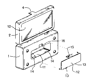
A tool case is provided with more storage than conventional tool cases, and has a lidded storage area which does not reduce the area available for primary storage. The box portion of the tool case has a recess in the bottom thereof, defining a secondary storage area on the opposite side of the case from the lid. The secondary storage area also has a lid, so that pieces can be stored without falling out.


French Abstract

Une boîte à outils comprenant davantage d'espace de rangement que les boîtes à outils classiques, et présentant un espace de rangement à couvercle qui ne réduit pas la zone disponible pour l'espace de rangement principal. La partie boîtier de la boîte à outils présente une cavité dans la partie inférieure de celle-ci, définissant un espace de rangement secondaire sur le côté opposé de la boîte à partir du couvercle. La zone de l'espace de rangement secondaire présente également un couvercle, ce qui permet de ranger les pièces sans qu'elles tombent.

Claims

Note: Claims are shown in the official language in which they were submitted.


THE EMBODIMENTS OF THE INVENTION IN WHICH AN EXCLUSIVE PROPERTY
OR PRIVILEGE IS CLAIMED ARE DEFINED AS FOLLOWS:
1. A tool case comprising a main box portion and a lid hinged to the box
portion, the main box portion having an upper surface with recesses defined
therein to
receive tools or components thereof, and a lower outer surface, said lower
outer
surface having a cavity therein defined by an inner surface and walls between
said
lower outer surface and said inner surface, so as to define a secondary
storage area
extending across only a portion of said lower surface, and further comprising
a cover
securable across said cavity to cover said cavity.
2. A tool case as recited in claim 1, where said cavity is elsewhere than
beneath recesses of the greatest depth.
3. A tool case as recited in claim 1, where said cover has small tabs
projecting from an edge thereof, which fit into slots in said main box portion
along an
edge of said cavity, and a resilient clip projecting from an opposite edge to
engage
means along an opposite edge of said cavity, to hold said cover in place.
4. A tool case, comprising:
a main box portion defined by a generally planar lower surface, four sidewalls
extending upwardly therefrom, and an upper surface extending across said main
box
portion, said upper surface of said main box portion having at least one large
recess
extending a substantial depth below said upper surface towards said lower
surface to
receive a tool, a plurality of smaller recesses extending only a short depth
below said
upper surface to receive components for use with said tool, and at least one
area
having no recesses; and
a lid hinged to said main box portion, said lid having a top and four
sidewalls
extending downwardly therefrom, at least a substantial portion of said top
being
transparent;
said lower surface having a cavity therein defined by an inner surface and
walls
between said lower surface and said inner surface, so as to define a secondary
storage
-5-

area extending upwardly towards said upper surface and extending across only a
portion of said lower surface, said cavity being positioned only beneath one
of said
unrecessed areas, and not beneath either said at least one large recess or
said smaller
recesses, said tool case further comprising a cover positionable across said
cavity to
cover said cavity.
5. A tool case as recited in claim 4, where said unrecessed areas have tool
component receiving elements extending upwardly therefrom, to hold tool
components
without using a recess.
6. A tool case as recited in claim 4, where said smaller recesses are angled
away from the horizontal to carry said components at an angle to the
horizontal such
that said components have an upper end projecting above said upper surface.
7. A tool case as recited in claim 4, said cover having tabs along one edge
which fit into holes in said main box portion adjacent said lower surface,
said cover
further having a resilient clip centered along an edge opposite the edge with
said tabs,
said resilient clip being configured to engage said main box portion to retain
said cover
in place.
8. A tool case as recited in claim 4, where said unrecessed areas have tool
component receiving elements extending upwardly therefrom, to hold tool
components
without using a recess, where said smaller recesses are angled away from the
horizontal to carry said components at an angle to the horizontal such that
said
components have an upper end projecting above said upper surface, and where
said
cover has tabs along one edge which fit into holes in said main box portion
adjacent
said lower surface, said cover further having a resilient clip centered along
an edge
opposite the edge with said tabs, said resilient clip being configured to
engage said
main box portion to retain said cover in place.
-6-

9. A tool case, comprising:
a main box portion defined by a generally planar lower surface, four sidewalls
extending upwardly therefrom, and an upper surface extending across said main
box
portion, said upper surface of said main box portion having at least one large
recess
extending a substantial depth below said upper surface towards said lower
surface to
receive a tool, a plurality of smaller recesses extending only a short depth
below said
upper surface to receive components for use with said tool, and at least one
area
having no recesses; and
a lid hinged to said main box portion, said lid having a top and four
sidewalls
extending downwardly therefrom, at least a substantial portion of said top
being
transparent;
said lower outer surface having a cavity therein defined by an inner surface
and walls
between said lower outer surface and said inner surface, so as to define a
secondary
storage area extending upwardly towards said upper surface and extending
across only
a portion of said lower surface, said cavity being positioned beneath at least
some of
said smaller recesses, and not beneath said at least one large recess, said
tool case
further comprising a cover positionable across said cavity to cover said
cavity, said
cover having tabs along one edge which fit into holes in said main box portion
adjacent
said lower surface, said cover further having a resilient clip centered along
an edge
opposite the edge with said tabs, said resilient clip being configured to
engage said
main box portion to retain said cover in place.
10. A tool case as recited in claim 9, where said unrecessed areas have tool
component receiving elements extending upwardly therefrom, to hold tool
components
without using a recess.
11. A tool case as recited in claim 9, where said smaller recesses are angled
away from the horizontal to carry said components at an angle to the
horizontal such
that said components have an upper end projecting above said upper surface.
12. A tool case as recited in claim 9, where said unrecessed areas have tool
component receiving elements extending upwardly therefrom, to hold tool
components
-7-

without using a recess, and where said smaller recesses are angled away from
the
horizontal to carry said components at an angle to the horizontal such that
said
components have an upper end projecting above said upper surface.
-8-

Description

Note: Descriptions are shown in the official language in which they were submitted.


2~ 89092
This invention relates to a tool case, particularly of the type used to
display a tool set at the point of sale, and to subsequently store the tool set. Such tool
cases are commonly referred to as "gift cases".
Cases of the general type are well known, and typically include an
5 open-topped box portion and a lid hinged to the box portion, with a clip to hold the lid
shut. A plastic insert in the box typically has recesses defined therein to accommodate
various tools and components, such as a screwdriver and various bits therefor. The lid
frequently has a transparent face, so that the tools can be seen when the case is
closed.
Such cases frequently have small bins provided by virtue of recesses in
the plastic insert, for storage of miscellaneous items (screws, for example) or for
secondary storage of the items in the tool set, i.e. instead of in the recesses designed
as their primary storage areas. However, since inexpensive, thin plastic is typically
used for the inserts, these bins have no structural rigidity, and no lid, so any bits or
other items are not contained, and can easily fall out. Also, any such bins reduce the
area available for storage of bits or other items in their primary recesses.
It is an object of the invention to provide an improved gift case, embodying
more storage than in conventional tool cases, and providing a lidded storage area which
does not reduce the area available for primary storage.
In the invention, the box portion of the tool case has a recess in the
bottom thereof, defining a secondary storage area on the opposite side of the case from
the lid. The secondary storage area also has a lid, so that pieces can be stored without
falling out.

2 1 890~2
The invention will now be described in detail with reference to the
accompanying drawings, in which:
Fig. 1 is a perspective view of a typical embodiment of the case, showing
the compartment in the underside thereof;
Fig. 2 a plan view of the embodiment of Fig. 1;
Fig. 3 is a bottom view of the embodiment of Fig. 1;
Fig. 4 is a side cross-section at 4-4 of Fig. 3;
Fig. 5 is a side cross-section at 5-5 of Fig. 3; and
Figs. 6 to 9 are plan view of other typical embodiments, configured for
various other tool sets.
Referring to the drawings, Fig. 1 shows the case, which includes a main
box portion 1 and a lid 2 hinged to the box portion, for example by two hinges 3,
typically integral "living" plastic hinges. A clip 4 holds the lid shut in conventional
fashion. The main box portion typically is blow moulded, and thus has a hollow area
between the outer shell and the plastic upper surface 5. The upper surface of the box
portion has various recesses 6 defined therein to accommodate tools and components,
such as a screwdriver or other large tool 8 and various bits or other small tools 9 to go
with the large tool. The recesses may include clips 7 to hold the items, or the items
may be held simply by virtue of a tight fit within the recesses, the recesses being
somewhat resilient. The lid typically has a transparent face 10, so that the tools can be
seen when the case is closed.
As seen most clearly in Figs. 1, 3 and 4, the box portion of the tool case
has a large recess in the bottom thereof, defining a secondary storage area 11 on the

~ 1 89092
opposite side of the case from the lid. The secondary storage area also has a lid 12,
so that pieces can be stored without falling out. The lid may be permanently attached,
or as shown, may be held in place by tabs 13 which fit into small holes or slots 14, with
a resilient clip 15 integral with the lid serving to hold the lid shut, the outermost portion
5 of the clip fitting into a small recess 16. The clip snaps into place in conventional
fashion by virtue of a small lip, such that it must be moved towards the main portion of
the lid in order to be released to allow the lid to be opened. Optional dividers 17 may
be provided within the storage area, if desired.
Preferably, in order to maximize the depth of the secondary storage area,
10 it is positioned beneath those components 9 which are positioned entirely above the
upper surface 5. However, the area could also be positioned in whole or in part
beneath recesses 6 for components 9, albeit with some loss of depth. The area would
not normally extend beneath the main tool 8, since the case would not normally provide
enough depth there. (If there is depth there, then the case really is oversized for the
15 tool set.)
It will be appreciated that many variations on the invention are possible,
in keeping with the principle of the invention. Figs. 6 to 9 for example show various
other possible configurations. Many others are obviously possible, and are
contemplated as being within the scope of the invention as defined by the
20 accompanying claims.
- 4 -

Representative Drawing
A single figure which represents the drawing illustrating the invention.
Administrative Status

2024-08-01:As part of the Next Generation Patents (NGP) transition, the Canadian Patents Database (CPD) now contains a more detailed Event History, which replicates the Event Log of our new back-office solution.

Please note that "Inactive:" events refers to events no longer in use in our new back-office solution.

For a clearer understanding of the status of the application/patent presented on this page, the site Disclaimer , as well as the definitions for Patent , Event History , Maintenance Fee  and Payment History  should be consulted.

Event History

Description Date
Inactive: Agents merged 2017-05-26
Time Limit for Reversal Expired 2014-10-29
Inactive: Office letter 2014-08-22
Inactive: Correspondence - Transfer 2014-07-22
Letter Sent 2013-10-29
Small Entity Declaration Request Received 2012-11-19
Revocation of Agent Requirements Determined Compliant 2011-11-17
Inactive: Office letter 2011-11-17
Appointment of Agent Requirements Determined Compliant 2011-11-17
Letter Sent 2010-03-19
Inactive: Office letter 2010-03-19
Inactive: Multiple transfers 2010-01-27
Inactive: IPC from MCD 2006-03-12
Grant by Issuance 2001-04-24
Inactive: Cover page published 2001-04-23
Letter Sent 2001-02-08
Inactive: Final fee received 2001-01-09
Pre-grant 2001-01-09
Inactive: Single transfer 2001-01-09
Letter Sent 2000-10-02
Notice of Allowance is Issued 2000-10-02
Inactive: Status info is complete as of Log entry date 2000-09-28
Inactive: Application prosecuted on TS as of Log entry date 2000-09-28
Inactive: Approved for allowance (AFA) 2000-09-13
Application Published (Open to Public Inspection) 1997-07-17
Request for Examination Requirements Determined Compliant 1996-10-29
All Requirements for Examination Determined Compliant 1996-10-29

Abandonment History

There is no abandonment history.

Maintenance Fee

The last payment was received on 2000-10-30

Note : If the full payment has not been received on or before the date indicated, a further fee may be required which may be one of the following

  • the reinstatement fee;
  • the late payment fee; or
  • additional fee to reverse deemed expiry.

Patent fees are adjusted on the 1st of January every year. The amounts above are the current amounts if received by December 31 of the current year.
Please refer to the CIPO Patent Fees web page to see all current fee amounts.

Owners on Record

Note: Records showing the ownership history in alphabetical order.

Current Owners on Record
TEAM FAIR HOLDINGS LIMITED
Past Owners on Record
KAILASH C. VASUDEVA
Past Owners that do not appear in the "Owners on Record" listing will appear in other documentation within the application.
Documents

To view selected files, please enter reCAPTCHA code :


To view images, click a link in the Document Description column. To download the documents, select one or more checkboxes in the first column and then click the "Download Selected in PDF format (Zip Archive)" or the "Download Selected as Single PDF" button.

List of published and non-published patent-specific documents on the CPD .

If you have any difficulty accessing content, you can call the Client Service Centre at 1-866-997-1936 or send them an e-mail at CIPO Client Service Centre.


Document
Description 
Date
(yyyy-mm-dd) 
Number of pages   Size of Image (KB) 
Abstract 1997-03-17 1 11
Description 1997-03-17 3 108
Claims 1997-03-17 1 23
Drawings 1997-03-17 4 119
Claims 2000-09-06 4 155
Representative drawing 2001-04-04 1 13
Representative drawing 1997-08-27 1 32
Reminder of maintenance fee due 1998-07-01 1 115
Commissioner's Notice - Application Found Allowable 2000-10-01 1 163
Courtesy - Certificate of registration (related document(s)) 2001-02-07 1 113
Courtesy - Certificate of registration (related document(s)) 2010-03-18 1 103
Maintenance Fee Notice 2013-12-09 1 170
Correspondence 2001-01-08 1 40
Correspondence 2010-03-18 1 17
Correspondence 2011-11-02 5 176
Correspondence 2011-11-16 1 13
Correspondence 2011-11-16 1 20
Correspondence 2012-11-18 4 58
Correspondence 2014-09-18 2 57
Correspondence 2000-01-16 2 62
Correspondence 1999-06-02 2 74
Correspondence 1995-06-07 1 29