Sélection de la langue

Search

Sommaire du brevet 2189092 

Énoncé de désistement de responsabilité concernant l'information provenant de tiers

Une partie des informations de ce site Web a été fournie par des sources externes. Le gouvernement du Canada n'assume aucune responsabilité concernant la précision, l'actualité ou la fiabilité des informations fournies par les sources externes. Les utilisateurs qui désirent employer cette information devraient consulter directement la source des informations. Le contenu fourni par les sources externes n'est pas assujetti aux exigences sur les langues officielles, la protection des renseignements personnels et l'accessibilité.

Disponibilité de l'Abrégé et des Revendications

L'apparition de différences dans le texte et l'image des Revendications et de l'Abrégé dépend du moment auquel le document est publié. Les textes des Revendications et de l'Abrégé sont affichés :

  • lorsque la demande peut être examinée par le public;
  • lorsque le brevet est émis (délivrance).
(12) Brevet: (11) CA 2189092
(54) Titre français: BOITE A OUTILS AVEC COMPARTIMENT DE RANGEMENT INFERIEUR
(54) Titre anglais: TOOL CASE WITH BOTTOM COMPARTMENT
Statut: Périmé et au-delà du délai pour l’annulation
Données bibliographiques
(51) Classification internationale des brevets (CIB):
  • B25H 3/02 (2006.01)
  • B25H 3/00 (2006.01)
  • B25H 3/06 (2006.01)
(72) Inventeurs :
  • VASUDEVA, KAILASH C. (Canada)
(73) Titulaires :
  • TEAM FAIR HOLDINGS LIMITED
(71) Demandeurs :
  • TEAM FAIR HOLDINGS LIMITED
(74) Agent: MERIZZI RAMSBOTTOM & FORSTER
(74) Co-agent:
(45) Délivré: 2001-04-24
(22) Date de dépôt: 1996-10-29
(41) Mise à la disponibilité du public: 1997-07-17
Requête d'examen: 1996-10-29
Licence disponible: S.O.
Cédé au domaine public: S.O.
(25) Langue des documents déposés: Anglais

Traité de coopération en matière de brevets (PCT): Non

(30) Données de priorité de la demande:
Numéro de la demande Pays / territoire Date
08/586,286 (Etats-Unis d'Amérique) 1996-01-16

Abrégés

Abrégé français

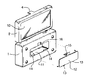
Une boîte à outils comprenant davantage d'espace de rangement que les boîtes à outils classiques, et présentant un espace de rangement à couvercle qui ne réduit pas la zone disponible pour l'espace de rangement principal. La partie boîtier de la boîte à outils présente une cavité dans la partie inférieure de celle-ci, définissant un espace de rangement secondaire sur le côté opposé de la boîte à partir du couvercle. La zone de l'espace de rangement secondaire présente également un couvercle, ce qui permet de ranger les pièces sans qu'elles tombent.


Abrégé anglais

A tool case is provided with more storage than conventional tool cases, and has a lidded storage area which does not reduce the area available for primary storage. The box portion of the tool case has a recess in the bottom thereof, defining a secondary storage area on the opposite side of the case from the lid. The secondary storage area also has a lid, so that pieces can be stored without falling out.

Revendications

Note : Les revendications sont présentées dans la langue officielle dans laquelle elles ont été soumises.


THE EMBODIMENTS OF THE INVENTION IN WHICH AN EXCLUSIVE PROPERTY
OR PRIVILEGE IS CLAIMED ARE DEFINED AS FOLLOWS:
1. A tool case comprising a main box portion and a lid hinged to the box
portion, the main box portion having an upper surface with recesses defined
therein to
receive tools or components thereof, and a lower outer surface, said lower
outer
surface having a cavity therein defined by an inner surface and walls between
said
lower outer surface and said inner surface, so as to define a secondary
storage area
extending across only a portion of said lower surface, and further comprising
a cover
securable across said cavity to cover said cavity.
2. A tool case as recited in claim 1, where said cavity is elsewhere than
beneath recesses of the greatest depth.
3. A tool case as recited in claim 1, where said cover has small tabs
projecting from an edge thereof, which fit into slots in said main box portion
along an
edge of said cavity, and a resilient clip projecting from an opposite edge to
engage
means along an opposite edge of said cavity, to hold said cover in place.
4. A tool case, comprising:
a main box portion defined by a generally planar lower surface, four sidewalls
extending upwardly therefrom, and an upper surface extending across said main
box
portion, said upper surface of said main box portion having at least one large
recess
extending a substantial depth below said upper surface towards said lower
surface to
receive a tool, a plurality of smaller recesses extending only a short depth
below said
upper surface to receive components for use with said tool, and at least one
area
having no recesses; and
a lid hinged to said main box portion, said lid having a top and four
sidewalls
extending downwardly therefrom, at least a substantial portion of said top
being
transparent;
said lower surface having a cavity therein defined by an inner surface and
walls
between said lower surface and said inner surface, so as to define a secondary
storage
-5-

area extending upwardly towards said upper surface and extending across only a
portion of said lower surface, said cavity being positioned only beneath one
of said
unrecessed areas, and not beneath either said at least one large recess or
said smaller
recesses, said tool case further comprising a cover positionable across said
cavity to
cover said cavity.
5. A tool case as recited in claim 4, where said unrecessed areas have tool
component receiving elements extending upwardly therefrom, to hold tool
components
without using a recess.
6. A tool case as recited in claim 4, where said smaller recesses are angled
away from the horizontal to carry said components at an angle to the
horizontal such
that said components have an upper end projecting above said upper surface.
7. A tool case as recited in claim 4, said cover having tabs along one edge
which fit into holes in said main box portion adjacent said lower surface,
said cover
further having a resilient clip centered along an edge opposite the edge with
said tabs,
said resilient clip being configured to engage said main box portion to retain
said cover
in place.
8. A tool case as recited in claim 4, where said unrecessed areas have tool
component receiving elements extending upwardly therefrom, to hold tool
components
without using a recess, where said smaller recesses are angled away from the
horizontal to carry said components at an angle to the horizontal such that
said
components have an upper end projecting above said upper surface, and where
said
cover has tabs along one edge which fit into holes in said main box portion
adjacent
said lower surface, said cover further having a resilient clip centered along
an edge
opposite the edge with said tabs, said resilient clip being configured to
engage said
main box portion to retain said cover in place.
-6-

9. A tool case, comprising:
a main box portion defined by a generally planar lower surface, four sidewalls
extending upwardly therefrom, and an upper surface extending across said main
box
portion, said upper surface of said main box portion having at least one large
recess
extending a substantial depth below said upper surface towards said lower
surface to
receive a tool, a plurality of smaller recesses extending only a short depth
below said
upper surface to receive components for use with said tool, and at least one
area
having no recesses; and
a lid hinged to said main box portion, said lid having a top and four
sidewalls
extending downwardly therefrom, at least a substantial portion of said top
being
transparent;
said lower outer surface having a cavity therein defined by an inner surface
and walls
between said lower outer surface and said inner surface, so as to define a
secondary
storage area extending upwardly towards said upper surface and extending
across only
a portion of said lower surface, said cavity being positioned beneath at least
some of
said smaller recesses, and not beneath said at least one large recess, said
tool case
further comprising a cover positionable across said cavity to cover said
cavity, said
cover having tabs along one edge which fit into holes in said main box portion
adjacent
said lower surface, said cover further having a resilient clip centered along
an edge
opposite the edge with said tabs, said resilient clip being configured to
engage said
main box portion to retain said cover in place.
10. A tool case as recited in claim 9, where said unrecessed areas have tool
component receiving elements extending upwardly therefrom, to hold tool
components
without using a recess.
11. A tool case as recited in claim 9, where said smaller recesses are angled
away from the horizontal to carry said components at an angle to the
horizontal such
that said components have an upper end projecting above said upper surface.
12. A tool case as recited in claim 9, where said unrecessed areas have tool
component receiving elements extending upwardly therefrom, to hold tool
components
-7-

without using a recess, and where said smaller recesses are angled away from
the
horizontal to carry said components at an angle to the horizontal such that
said
components have an upper end projecting above said upper surface.
-8-

Description

Note : Les descriptions sont présentées dans la langue officielle dans laquelle elles ont été soumises.


2~ 89092
This invention relates to a tool case, particularly of the type used to
display a tool set at the point of sale, and to subsequently store the tool set. Such tool
cases are commonly referred to as "gift cases".
Cases of the general type are well known, and typically include an
5 open-topped box portion and a lid hinged to the box portion, with a clip to hold the lid
shut. A plastic insert in the box typically has recesses defined therein to accommodate
various tools and components, such as a screwdriver and various bits therefor. The lid
frequently has a transparent face, so that the tools can be seen when the case is
closed.
Such cases frequently have small bins provided by virtue of recesses in
the plastic insert, for storage of miscellaneous items (screws, for example) or for
secondary storage of the items in the tool set, i.e. instead of in the recesses designed
as their primary storage areas. However, since inexpensive, thin plastic is typically
used for the inserts, these bins have no structural rigidity, and no lid, so any bits or
other items are not contained, and can easily fall out. Also, any such bins reduce the
area available for storage of bits or other items in their primary recesses.
It is an object of the invention to provide an improved gift case, embodying
more storage than in conventional tool cases, and providing a lidded storage area which
does not reduce the area available for primary storage.
In the invention, the box portion of the tool case has a recess in the
bottom thereof, defining a secondary storage area on the opposite side of the case from
the lid. The secondary storage area also has a lid, so that pieces can be stored without
falling out.

2 1 890~2
The invention will now be described in detail with reference to the
accompanying drawings, in which:
Fig. 1 is a perspective view of a typical embodiment of the case, showing
the compartment in the underside thereof;
Fig. 2 a plan view of the embodiment of Fig. 1;
Fig. 3 is a bottom view of the embodiment of Fig. 1;
Fig. 4 is a side cross-section at 4-4 of Fig. 3;
Fig. 5 is a side cross-section at 5-5 of Fig. 3; and
Figs. 6 to 9 are plan view of other typical embodiments, configured for
various other tool sets.
Referring to the drawings, Fig. 1 shows the case, which includes a main
box portion 1 and a lid 2 hinged to the box portion, for example by two hinges 3,
typically integral "living" plastic hinges. A clip 4 holds the lid shut in conventional
fashion. The main box portion typically is blow moulded, and thus has a hollow area
between the outer shell and the plastic upper surface 5. The upper surface of the box
portion has various recesses 6 defined therein to accommodate tools and components,
such as a screwdriver or other large tool 8 and various bits or other small tools 9 to go
with the large tool. The recesses may include clips 7 to hold the items, or the items
may be held simply by virtue of a tight fit within the recesses, the recesses being
somewhat resilient. The lid typically has a transparent face 10, so that the tools can be
seen when the case is closed.
As seen most clearly in Figs. 1, 3 and 4, the box portion of the tool case
has a large recess in the bottom thereof, defining a secondary storage area 11 on the

~ 1 89092
opposite side of the case from the lid. The secondary storage area also has a lid 12,
so that pieces can be stored without falling out. The lid may be permanently attached,
or as shown, may be held in place by tabs 13 which fit into small holes or slots 14, with
a resilient clip 15 integral with the lid serving to hold the lid shut, the outermost portion
5 of the clip fitting into a small recess 16. The clip snaps into place in conventional
fashion by virtue of a small lip, such that it must be moved towards the main portion of
the lid in order to be released to allow the lid to be opened. Optional dividers 17 may
be provided within the storage area, if desired.
Preferably, in order to maximize the depth of the secondary storage area,
10 it is positioned beneath those components 9 which are positioned entirely above the
upper surface 5. However, the area could also be positioned in whole or in part
beneath recesses 6 for components 9, albeit with some loss of depth. The area would
not normally extend beneath the main tool 8, since the case would not normally provide
enough depth there. (If there is depth there, then the case really is oversized for the
15 tool set.)
It will be appreciated that many variations on the invention are possible,
in keeping with the principle of the invention. Figs. 6 to 9 for example show various
other possible configurations. Many others are obviously possible, and are
contemplated as being within the scope of the invention as defined by the
20 accompanying claims.
- 4 -

Dessin représentatif
Une figure unique qui représente un dessin illustrant l'invention.
États administratifs

2024-08-01 : Dans le cadre de la transition vers les Brevets de nouvelle génération (BNG), la base de données sur les brevets canadiens (BDBC) contient désormais un Historique d'événement plus détaillé, qui reproduit le Journal des événements de notre nouvelle solution interne.

Veuillez noter que les événements débutant par « Inactive : » se réfèrent à des événements qui ne sont plus utilisés dans notre nouvelle solution interne.

Pour une meilleure compréhension de l'état de la demande ou brevet qui figure sur cette page, la rubrique Mise en garde , et les descriptions de Brevet , Historique d'événement , Taxes périodiques et Historique des paiements devraient être consultées.

Historique d'événement

Description Date
Inactive : Regroupement d'agents 2017-05-26
Le délai pour l'annulation est expiré 2014-10-29
Inactive : Lettre officielle 2014-08-22
Inactive : Correspondance - Transfert 2014-07-22
Lettre envoyée 2013-10-29
Requête visant une déclaration du statut de petite entité reçue 2012-11-19
Exigences relatives à la révocation de la nomination d'un agent - jugée conforme 2011-11-17
Inactive : Lettre officielle 2011-11-17
Exigences relatives à la nomination d'un agent - jugée conforme 2011-11-17
Lettre envoyée 2010-03-19
Inactive : Lettre officielle 2010-03-19
Inactive : Transferts multiples 2010-01-27
Inactive : CIB de MCD 2006-03-12
Accordé par délivrance 2001-04-24
Inactive : Page couverture publiée 2001-04-23
Lettre envoyée 2001-02-08
Inactive : Taxe finale reçue 2001-01-09
Préoctroi 2001-01-09
Inactive : Transfert individuel 2001-01-09
Lettre envoyée 2000-10-02
Un avis d'acceptation est envoyé 2000-10-02
Inactive : Renseign. sur l'état - Complets dès date d'ent. journ. 2000-09-28
Inactive : Dem. traitée sur TS dès date d'ent. journal 2000-09-28
Inactive : Approuvée aux fins d'acceptation (AFA) 2000-09-13
Demande publiée (accessible au public) 1997-07-17
Exigences pour une requête d'examen - jugée conforme 1996-10-29
Toutes les exigences pour l'examen - jugée conforme 1996-10-29

Historique d'abandonnement

Il n'y a pas d'historique d'abandonnement

Taxes périodiques

Le dernier paiement a été reçu le 2000-10-30

Avis : Si le paiement en totalité n'a pas été reçu au plus tard à la date indiquée, une taxe supplémentaire peut être imposée, soit une des taxes suivantes :

  • taxe de rétablissement ;
  • taxe pour paiement en souffrance ; ou
  • taxe additionnelle pour le renversement d'une péremption réputée.

Veuillez vous référer à la page web des taxes sur les brevets de l'OPIC pour voir tous les montants actuels des taxes.

Titulaires au dossier

Les titulaires actuels et antérieures au dossier sont affichés en ordre alphabétique.

Titulaires actuels au dossier
TEAM FAIR HOLDINGS LIMITED
Titulaires antérieures au dossier
KAILASH C. VASUDEVA
Les propriétaires antérieurs qui ne figurent pas dans la liste des « Propriétaires au dossier » apparaîtront dans d'autres documents au dossier.
Documents

Pour visionner les fichiers sélectionnés, entrer le code reCAPTCHA :


Pour visualiser une image, cliquer sur un lien dans la colonne description du document. Pour télécharger l'image (les images), cliquer l'une ou plusieurs cases à cocher dans la première colonne et ensuite cliquer sur le bouton "Télécharger sélection en format PDF (archive Zip)" ou le bouton "Télécharger sélection (en un fichier PDF fusionné)".

Liste des documents de brevet publiés et non publiés sur la BDBC .

Si vous avez des difficultés à accéder au contenu, veuillez communiquer avec le Centre de services à la clientèle au 1-866-997-1936, ou envoyer un courriel au Centre de service à la clientèle de l'OPIC.


Description du
Document 
Date
(aaaa-mm-jj) 
Nombre de pages   Taille de l'image (Ko) 
Abrégé 1997-03-18 1 11
Description 1997-03-18 3 108
Revendications 1997-03-18 1 23
Dessins 1997-03-18 4 119
Page couverture 1997-03-18 1 16
Page couverture 1998-08-20 1 16
Page couverture 2001-04-05 1 34
Revendications 2000-09-07 4 155
Dessin représentatif 2001-04-05 1 13
Dessin représentatif 1997-08-28 1 32
Rappel de taxe de maintien due 1998-07-02 1 115
Avis du commissaire - Demande jugée acceptable 2000-10-02 1 163
Courtoisie - Certificat d'enregistrement (document(s) connexe(s)) 2001-02-08 1 113
Courtoisie - Certificat d'enregistrement (document(s) connexe(s)) 2010-03-19 1 103
Avis concernant la taxe de maintien 2013-12-10 1 170
Correspondance 2001-01-09 1 40
Correspondance 2010-03-19 1 17
Correspondance 2011-11-03 5 176
Correspondance 2011-11-17 1 13
Correspondance 2011-11-17 1 20
Correspondance 2012-11-19 4 58
Correspondance 2014-09-19 2 57
Correspondance 2000-01-17 2 62
Correspondance 1999-06-03 2 74
Correspondance 1995-06-08 1 29