Note: Descriptions are shown in the official language in which they were submitted.
WO 95!32748 218 9 2 3 ~ pC.l.~s94106073
1
SELF-SEALING VALVE DEVICE FOR ANGIOGRAPHIC CATHETERS
Technical Field
The present invention relates generally to
angiographic catheters used to access a blood vessel,
and more particularly, to devices for sealing the
external end of an angiographic catheter or needle
following insertion of such devices into the vascular
system.
Background Art
l0 Catheters and needles are inserted into the
vascular system for many reasons including, diagnosis,
therapy or to draw blood samples. During an
angiographic procedure, a catheter is placed into the
vascular system commonly using a Seldinger technique.
This technique consists of placing a needle
percutaneously into a blood vessel of the vascular
system, and then threading a flexible guidewire through
the lumen of the needle into the blood vessel. The
guidewire is left in place within the blood vessel, and
the needle is thereafter removed. The distal tip of the
catheter is then threaded over the external end of the
guidewire and advanced therealong and positioned within
the vascular system in accordance with the prior
placement of the guidewire; the guidewire is thereafter
removed. Diagnostic fluids may then be injected into
the blood vessel to diagnose or treat various vascular
conditions.
The steps described above must often be repeated
during a procedure in order to manipulate the catheter,
i.e., to move the catheter into various branches of the
vascular system. To perform such manipulation, the
guidewire is reinserted into the catheter, and the
guidewire and catheter are then manipulated to the new
position.
The angiographic catheter includes a fluid-
communicating lumen extending between the distal end and
proximal end thereof. Upon introduction of the distal
end of the catheter into the blood vessel, blood
pressure within the body forces blood into the catheter
PCT/US94l06073
WO 95132748 218 9 2 3
2
lumen. Some blood may escape from the proximal end of
the catheter even before the guidewire is removed by
flowing through the annulus between the guidewire and
the inner walls of the catheter. Once the guidewire is
withdrawn from the catheter, the outward flow of blood
through the lumen of the catheter is essentially
unimpeded.
Physicians prefer to minimize the amount of blood
leakage from angiographic catheters for two compelling
reasons. First, it is important to prevent blood loss
from the patient to avoid the need for blood
transfusions. Secondly, blood may contain highly
infectious material such as hepatitis or AIDS to which
medical personnel are exposed, and it is therefore
beneficial to medical personnel to limit blood loss.
In order to prevent blood from freely draining out
of the angiographic catheter, a first port of a stopcock
is commonly secured by means of a luer lock connection
to the proximal end of the catheter external to the
patient. Such stopcocks are well known and include a
manually rotatable handle or lever operated by the thumb
and forefinger for selectively opening or sealing the
proximal end of the catheter. Such stopcocks typically
include a second port, also provided with a luer lock
connection fitting, in fluid communication with the
first port thereof when the stopcock is open. In order
to draw blood from the patient into a syringe, or to
inject a substance into the blood vessel through the
catheter, the stopcock must be turned by hand into the
opened position. When the catheter is not being used to
perform aspiration or infusion, it is standard medical
practice to inject heparinized saline through the
catheter while closing the stopcock. This anticoagulant
solution flushes any blood from the catheter and
thereafter prevents blood from entering the catheter and
clotting inside.
As described above, during vascular procedures
involving catheters, it is common to pass a guidewire
into the proximal end of the catheter to help guide the
2189234
WO 95/32748 PCT/US94/06073
3
catheter tip into a selected blood vessel. If a
stopcock has been secured to the proximal~end of the
catheter, then the stopcock must first be opened so that
the distal tip of the guidewire may be passed through
the opened stopcock into the catheter. When the
stopcock is opened, the heparinized saline that was
previously injected into the catheter is flushed out by
the blood. The guidewire is passed into the catheter
which now contains stagnant blood which can form blood
clots between the guidewire and the inner wall of the
catheter. Moreover, during guidewire manipulations, the
stopcock must be left open to permit passage of the
guidewire; accordingly, blood can flow between the
guidewire and inner lumen of the catheter, and often
drips out at the second port of the stopcock. This slow
flow of escaping blood may form clots within the
catheter; these blood clots can be forced back into the
vascular system when the guidewire is advanced or when
subsequent injections are made through the catheter.
Introduction of such blood clots can result in blocked
blood vessels; if these blood vessels are critical, for
example, the coronary arteries, it is possible that
permanent, severe damage can occur.
Thus, while conventional stopcocks help to reduce
the outflow of blood through angiographic catheters,
they are only partially effective. Blood often flows
out of a stopcock when opened for a guidewire to pass
through it, or when a connection is made to a syringe or
an infusion line. Moreover, conventional stopcocks are
cumbersome because they often require two hands for
operation. One hand holds the stopcock while the other
turns the lever. This maneuver may be difficult for a
physician to achieve, particularly when, for example,
one of the physician's hands is needed to maintain the
position of the catheter.
Another problem related to stopcocks arises when a
catheter that has been fitted with a stopcock must be
attached to a power injector, for example, when a large
quantity of x-ray dye is to be injected while obtaining
218923
WO 95/32748 PCT/US94106073
4
radiographs to visualize the blood vessel. The
physician sometimes forgets to turn the stopcock into
the opened position, in which case the dye is prevented
from entering the catheter. The radiographs are
obtained but do not provide the desired diagnostic
information because the dye was not injected. The
patient is therefore unnecessarily exposed to radiation,
and the procedure must be repeated by the physician a
second time to obtain the desired diagnostic
information.
Apart from conventional stopcocks, other devices
are known for reducing blood loss through angiographic
catheters. For example, a variety of hemostasis valves
are known which may be secured to the proximal end of an
angiographic catheter to minimize blood loss around a
guidewire that is positioned within a catheter, while
permitting fluid to be injected into the catheter with
the guidewire in place. One example of such a
hemostasis valve is available from Cordis Corporation of
Miami, Florida under the product name "Adjustable
Hemostasis Valve", Catalog No. 501-622. Such device
includes a male luer lock connection fitting for being
secured over the proximal end of an angiographic
catheter. The device also includes a rotatable barrel
which can be manually rotated to adjust the degree of
compression exerted upon an annular compression washer.
A guidewire may be inserted through the central opening
in the rotatable barrel and passed into the proximal end
of the catheter. The barrel can then be manually
rotated to tighten the compression washer to form a seal
about the guidewire. The device also includes a
sideport extension with a luer lock fitting to permit
flushing and/or infusion of fluids. However, such
device must be manipulated by the physician to adjust
the degree to which the compression washer seals against
the walls of the guidewire. In addition, if the
guidewire is to be removed, the device must again be
manually rotated, first to release the guidewire, and
thereafter to reseal the guidewire passage. As noted
WO 95/32748 218 9 2 3 4 pCT/US94/06073
above, the physician's hands are often required for
other purposes. A similar type of device is also
available under the product name "Tuohy-Borst Adapter"
from Universal Medical Instrument Corp. of Ballston Spa,
5 New York; the latter device includes a sideport
extension through which a high pressure injection of
fluid may be made while the guidewire is clamped
therein.
Another device which has been introduced to avoid
leakage of blood from angiographic catheters is
available from Medi-tech, Incorporated of Watertown,
Massachusetts under the product name "FloSwitch HP",
Catalog No. 44-200. This product resembles the device
described within U.S. Patent No. 4,243,034 issued to
Brandt, and is further described in Widlus, "Technical
Note: Safety of High Pressure Injections Through a Flow
Switch Stopcock", Cardioyascular and Interventional
Radiology, (1988) 11:307-308. The device includes a
male luer connector at one end for being secured to the
proximal end of the catheter, and includes an opposing
end provided with a female luer connector for allowing a
syringe to be secured thereto. The device includes a
sliding thumb switch which may be opened or closed with
or without a guidewire in place. If a guidewire is
passed through such device, the slide switch may be
advanced toward the closed position until the movable
sealing member engages the wall of the guidewire to
minimize blood leakage. While representing an
improvement over a conventional stopcock or simple
hemostasis valve, the "FloSwitch HP" flow control device
still requires manual operation by the physician, and
still allows a physician to forget that he has left the
switch in the closed position when attempting to inject
dye into the catheter.
Hemostasis valves using deformable elastomeric
seals are widely known for use within catheter
introduces sheaths. Such catheter introduces sheaths
are available from a variety of manufacturers, including
the catheter sheath introduces available from Cordis
PCT/US94/06073
WO 95/32748 218 9 2 3 -~
6
Corporation of Miami, Florida under the product name
"Catheter Sheath Introduces", Catalog No. 501-675U.
Patents generally directed to such catheter introduces
sheaths include U.S. Patent No. 4,610,665 (Matsumoto et
al.); No. 4,626,245 (Weinstein); No. 4,000,739
(Stevens); No. 4,430,081 (Timmermans); and No. 4,673,393
(Suzuki et al.). While such introduces sheaths are
effective in preventing blood loss which would otherwise
result when a catheter or guidewire is inserted
therethrough, such devices do not solve the problem of
preventing blood loss from the proximal end of an
angiographic catheter of the type used to inject fluids
under high pressure within the vascular system.
Finally, a variety of devices are known which
include deformable elastomeric seals that are adapted to
form a fluid seal but which are deformed upon insertion
of the tip of a syringe or other conical member to
permit fluid flow therethrough. Examples of such
devices are described within U.S. Patent No. 3,837,381
(Arroyo); No. 4,143,853 (Abramson); No. 4,387,879
(Tauschinski); No. 4,765,588 (Atkinson); No. 4,842,591
(Luther); and United Kingdom Patent No. 2,067,075
(Krutten et al.). In particular, the patent to Abramson
describes a check valve for use with a catheter or
needle and including a slit rubber disc supported in a
housing having a first male connection having a standard
luer-type taper and having a second luer-type female
connection. The valve device is described for use in
conjunction with a needle having a luer-type female
fitting for withdrawing blood samples. Blood samples
are withdrawn by inserting into the female connection of
the check valve the tip of a syringe having a male
connector at its tip to spread apart the slit in the
valve. However, no suggestion is made in such
disclosure of the use of such a check valve in
conjunction with an angiographic catheter, or for
passage of a guidewire therethrough.
The above-mentioned patent to Tauschinski discloses
a self-sealing connector for coupling a vein catheter to
218923
WO 95/32748 PCT/US94/06073
7
a supply of blood or parenteral solution. The described
device includes a slit elastic disc to selectively seal
the flow of fluid. In at least one embodiment, an
axially slidable member having a central bore is
advanced into contact with the slit disc to open the
same when the end of a supply hose is inserted into one
of the ports of the device. Once again, no suggestion
is made that such a device is capable of being used in
conjunction with an angiographic catheter, that a
guidewire be passed through the elastic disc, or that
such a device is adapted for high pressure injections of
fluid into an angiographic catheter.
The above-mentioned patent to Atkinson discloses a
check valve for coupling a syringe to a fluid supply
container for allowing a user to withdraw fluid from the
supply container into the syringe. The check valve
includes a slit elastomeric diaphragm. Insertion of the
distal end of the syringe into the check valve causes
such distal end to push through the slit diaphragm.
The above-mentioned patent to Luther describes a
one-way valve connector for coupling a syringe tip to a
catheter. The one-way valve includes a resilient slit
septum that can be deformed by a movable plug.
Insertion of the syringe tip causes the plug to move
forwardly to deform the septum for allowing liquid to be
injected therethrough. Again, no suggestion is made
that such a check valve may be used with an angiographic
. catheter, or that a guidewire be passed through the slit
of the resilient septum.
In addition, U.S. Patent No. 3,601,151 to Winnard
discloses a one way valve which, in one embodiment, is
coupled between a needle inserted into a vein and a
syringe used to withdraw blood samples. Such device
does not include a slit seal and is not adapted to
permit passage of a guidewire therethrough.
Accordingly, it is an object of the present
invention to provide a device which can be secured to an
angiographic catheter to prevent and/or minimize the
loss of blood from the proximal end of such catheter
PCT/US94/06073
WO 95/32748
8
following placement of the catheter within a blood
vessel.
Another object of the present invention is to
minimize blood loss from an angiographic catheter when
inserting a guidewire therein.
Another object of the present invention is to
provide such a device which permits a guidewire to be
freely passed through an angiographic catheter while
providing a seal around the guidewire to prevent any
l0 blood from passing between the guidewire and catheter
while the guidewire is present.
Another object of the present invention is to
prevent or minimize blood loss from an angiographic
catheter when connecting or disconnecting a syringe or
infusion line thereto.
Still another object of the present invention is to
provide such a device which permits a syringe to be
coupled to the proximal end of the catheter while
effecting a fluid-tight, high-pressure seal
therebetween.
Yet another object of the present invention is to
provide such a device which does not require any
manipulation of levers or switches in order to pass a
guidewire into the proximal end of the catheter, and
which similarly does not require any manipulation of
levers or switches in order to inject or aspirate a
fluid therethrough.
A further object of the present invention is to
provide such a device which prevents heparinized saline
or other anticoagulant fluid from being flushed out of
the catheter when a syringe or fluid line is uncoupled
from the proximal end of the catheter or when a
guidewire is inserted into the catheter.
A still further object of the present invention to
provide such a device which is of simple and inexpensive
construction.
Another object of the present invention is to
provide such a device which automatically opens when a
syringe or other medical injection line is attached to
2189234
WO 95/32748 PCT/US94/06073
9
it; similarly, when the syringe or injection line is
removed therefrom, the device automatically closes
without any intervention by the physician.
These and other objects of the invention will
become more apparent to those skilled in the art as the
description of the invention proceeds.
Disclosure of Invention
Briefly described, and in accordance with a
preferred embodiment thereof, the present invention is a
to self-sealing valve device for use with angiographic
catheters, and including a housing having a first end
adapted to form a luer lock connection with the proximal
end of the angiographic catheter for forming a fluid
tight coupling therewith. The housing includes a second
opposing end including a female luer lock connection
fitting adapted to receive a complementary male luer
lock connection fitting of a syringe, stopcock, or the
like, to form a fluid tight connection therewith. The
housing includes a central bore extending between the
first and second opposing ends along a longitudinal axis
of said housing. A deformable elastomeric seal is
supported within the housing and extends across the
central bore thereof to selectively seal the central
bore. The deformable elastomeric seal includes a slit
substantially aligned with the longitudinal axis of said
housing to permit a guidewire to be passed therethrough
while sealingly engaging the guidewire to prevent blood,
heparinized saline, or other fluid within the catheter
from passing beyond the deformable elastomeric seal.
As described above, the second end of the housing
is provided with a female luer lock connection fitting
for receiving a mating male luer lock connector. The
self-sealing valve device of the present invention
further includes a mechanism for deforming the
aforementioned elastomeric seal automatically upon
coupling of a male luer lock connection fitting to the
second end of the housing in order to permit passage of
blood or other fluids through the deformable elastomeric
seal and through the central bore of the housing
PCT/US94/06073
WO 95132748 218 9 2 3 ~
following connection of a syringe, stopcock, or the
like, to the second end of the housing.
In one embodiment of the present invention, this
function is achieved by positioning the deformable
5 elastomeric seal within the housing at a distance from
the second end of the housing commensurate with the
distance by which the conical tip of the syringe or
other instrument extends into the second end of the
housing for causing the conical tip of the syringe,
10 stopcock, or the like, to directly contact and deform
the deformable elastomeric seal in order to permit the
passage of fluids therethrough. A guidance member may
be provided for use in conjunction with such a device
for guiding and supporting a guidewire to be passed
through the slit of the deformable elastomeric seal.
In a second embodiment, the mechanism for deforming
the elastomeric seal includes a depressor member
supported within the housing for movement along the
longitudinal axis of the housing between the seal and
the second end of the housing. The depressor member has
a central bore extending therethrough concentric with
the longitudinal axis of the housing for permitting the
passage of a guidewire or fluids therethrough. The
depressor member has a first end disposed proximate the
deformable elastomeric seal for contacting and deforming
the seal when urged thereagainst. The depressor member
also includes a second opposing end disposed proximate
the second end of the housing and having an inwardly
tapering conical surface for being abutted by the
conical tip of a syringe, stopcock, or the like,
connected to the second end of the housing. The
insertion of the conical tip of the syringe, stopcock,
or the like causes the depressor member to advance
toward the deformable elastomeric seal to break the seal
to permit fluids to pass therethrough. Preferably, the
central bore of the housing includes a reduced-diameter
portion proximate to the deformable elastomeric seal and
disposed between said deformable elastomeric seal and
the first end of the housing. The reduced-diameter
2i8923~
WO 95/32748 PCT/US94/06073
11
portion provides a shoulder against which the deformable
elastomeric seal rests when deformed, the shoulder
thereby preventing excessive deformation of the
deformable elastomeric seal.
Another aspect of the present invention relates to
the incorporation of such a self-sealing valve device
within the proximal end of an angiographic catheter as a
unitary device ready for use.
Yet another aspect of the present invention is a
method of performing an angiographic procedure using an
angiographic catheter wherein the distal end of an
angiographic catheter is placed within a blood vessel of
a body and a deformable elastomeric seal having a slit
formed therein is provided substantially adjacent the
proximal end of the catheter to selectively seal the
proximal end of the catheter against the loss of blood.
or other fluids therefrom. A fluid-tight coupling is
then formed between the tip of a syringe and the
proximal end of the catheter, while simultaneously
deforming the deformable elastomeric seal to permit
fluid to be passed therethrough or blood to be aspirated
therethrough. Fluid is injected under pressure from the
syringe through the deformable elastomeric seal and into
the catheter for introducing the fluid under pressure
into the body. The syringe is uncoupled from the
proximal end of the catheter, while permitting the
deformable elastomeric seal to return to its original
position sealing the proximal end of the catheter. The
step of providing the deformable elastomeric seal is
preferably achieved by providing a housing having first
and second opposing ends and including a central bore
extending therebetween, supporting the deformable
elastomeric seal within the housing and extending across
the central bore, and forming a luer lock connection
between a first end of the housing and the proximal end
of the catheter. The step of forming a fluid-tight
coupling between the tip of a syringe and the proximal
end of the catheter is preferably achieved by forming a
luer lock connection between the tip of the syringe and
218923
WO 95132748 PCT/US94/06073
12
the second end of the housing.
The method of the present invention may also
include the further step of inserting a guidewire
through both the proximal end of the catheter and the
slit of the deformable elastomeric seal, and passing the
guide wire into the body through the catheter in order
to position the guidewire within a blood vessel of the
body.
Brief Description of the Drawings
to Fig. 1 is a perspective view of a self-sealing
valve device for use with an angiographic catheter in
accordance with the present invention, and further
partially illustrates the proximal end of an
angiographic catheter as well as the distal tip of a
syringe.
Fig. 2 is a sectional view of the components shown
in Fig. 1 viewed through the plane designated by arrows
2-2 as shown in Fig. 1.
Fig. 3 is a sectional view like that of Fig. 2 but
directed to an alternate embodiment of the present
invention, and including a guidance member for guiding a
guidewire for passage through a deformable seal of the
valve device.
Fig. 4 is a sectional view of the self-sealing
valve device shown in Fig. 3 wherein the distal tip of a
syringe engages and deforms the elastomeric seal of the
valve device.
Figs. 5A-5G illustrate steps of a method for
performing an angiographic procedure.
3o Fig. 5A illustrates a guidewire inserted within a
blood vessel of a body.
Fig. 5B illustrates an angiographic catheter
equipped with a self-sealing valve device being guided
over the guidewire into the blood vessel.
Fig. 5C illustrates the guidewire being removed
from the angiographic catheter.
Fig. 5D illustrates a syringe being coupled by a
luer lock connection fitting with the self-sealing valve
device for injecting fluid into the catheter.
WO 95/32748 ~ ~ ~ PCT/US94/06073
13
Fig. 5E illustrates the syringe being detached from
the valve device.
Fig. 5F illustrates the guidewire being passed into
the valve device and through the catheter into the blood
vessel.
Fig. 5G illustrates the angiographic catheter being
removed from the guidewire.
Best Mode for Carrying Out the Invention
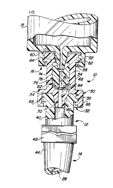
Within Fig. 1, a self-sealing valve device,
l0 constructed in accordance with one embodiment of the
present invention, is designated generally by reference
numeral 10. Also shown in Fig. 1 is the proximal end 12
of an angiographic catheter 14, as well as the distal
tip 16 of a syringe 18.
Before further describing self-sealing valve device
10, it will be helpful to first describe the structure
of angiographic catheter 14. Catheter 14 includes a
central, flexible shaft 20 which extends between
proximal end 12 and an opposing distal end; this
opposing distal end is visible within, for example, Fig.
5D and is designated therein by reference numeral 22.
As indicated within Fig. 5D, distal end 22 of
angiographic catheter 14 is adapted to be inserted into
a blood vessel 24 of a patient's body 26. As indicated
in Figs. 1 and 2, a lumen 28 extends continuously
through catheter 14 from proximal end 12 to distal end
22. Lumen 28 allows fluids to be passed through
catheter 14, and also is adapted to receive a guidewire
30, as shown in Fig. 5B, to properly position catheter
14 within body 26.
Returning to Figs. 1 and 2, proximal end 12 of
angiographic catheter 14 includes a female luer lock
connection fitting 32 which terminates in an annular
sealing surface 34. Extending below sealing surface 34
is a cylindrical surface 36 upon which a single raised
thread 38 is formed; raised thread 38 gradually spirals
upwardly toward annular sealing surface 34. A reduced
diameter cylindrical portion 40 couples female luer lock
connection fitting 32 to squared portion 42, adapted to
218923'T
WO 95132748 PCT/US94/06073
14
be grasped by a physician to steady catheter 14 when
making or removing connections to luer lock connector
32. Conically tapered portion 44 of proximal end 12
joins with the upper end of shaft 20 of catheter 14.
As shown in Figs. 1 and 2, female luer lock
connector 32 of angiographic catheter 14 includes an
inwardly converging conical bore 46 which extends
through the center of annular sealing surface 34 and
which communicates with lumen 28. Female luer lock
l0 connector 32 is adapted to receive a complimentary male
luer lock connection fitting to form a fluid tight
connection therewith; such a complimentary male luer
lock connection fitting may be provided by, for example,
distal end 16 of syringe 18, or by a port of a
conventional stopcock, an infusion line, or the like.
The features of angiographic catheter 14, including the
structure of female luer lock connector 32 are well
known in the art and do not form part of the present
invention. However, an understanding of such features
is helpful to an understanding the features of the
present invention, which will now be described in
greater detail.
Referring to Figs. 1 and 2, self-sealing valve
device 10 includes a housing 48, which is preferably
molded from a medical-grade plastic similar to materials
commonly used, for example, to mold proximal end 12 of
catheter 14. Housing 48 includes a first end 50 and an
opposing second end 52. A central bore 54 (see Fig. 2)
extends continuously between first end 50 and second end
52 of housing 48 along longitudinal axis 56 of housing
48.
Second end 52 of housing 48 includes a female luer
lock connection fitting 58 substantially identical in
structure to female luer lock connector 32 described
above in conjunction with the proximal end 12 of
catheter 14. Female luer lock connector 58 includes an
annular sealing surface 60, a raised spiral thread 62,
and an inwardly converging conical bore 64 in fluid
communication with central bore 54 of housing 48. Like
2189234
WO 95/32748 PCT/US94/06073
female luer connector 32, female luer connector 58 is
adapted to receive a complimentary male luer lock
connection fitting of a syringe, stopcock, infusion line
or the like, to form a fluid-tight connection therewith.
5 As shown in Figs. 1 and 2, first end 50 of housing
48 includes a male luer lock connection fitting 66
adapted to be releasably secured with female luer lock
connector 32 of catheter 14 in order to form a fluid-
tight coupling therebetween. Male luer lock connector
10 66 includes a cylindrical extension 68 which preferably
has a knarled outer surface, as shown in Fig. 1, for
allowing a physician to more easily grip and rotate
valve device 10 when securing the same to the proximal
end 12 of catheter 14. As shown best in Fig. 2,
15 cylindrical extension 68 is internally threaded for
releasably receiving raised thread 38 of female luer
lock connector 32. Male luer lock connector 50 further
includes a conically-tapered tip portion 70 adapted to
extend within conical bore 46 of female luer lock
connector 32. The degree of taper of conical portion 70
is identical to that of conical bore 46 in order to
effect a fluid-tight seal between male luer lock
connector 50 and female luer lock connector 32 when such
components are threaded together. Conical tip portion
70 includes a central bore 72 extending concentric with
bore 54 for permitting fluids and/or a guidewire to be
passed therethrough.
The male lock luer connector fitting 16 of syringe
18 essentially has the same features as those described
immediately above for male lock luer connector 50. In
particular, male lock luer connector 16 of syringe 18
includes a conically tapered tip portion 74 adapted to
extend through, and sealingly engage, conical bore 64 of
female luer lock connector 58.
As shown in Fig. 2, valve device 10 further
includes a deformable elastomeric seal 76 supported
within housing 48 and extending across central bore 54
thereof. Deformable elastomeric seal 76 includes a
2189234
16
central slit formed therein substantially aligned with
longitudinal axis 56 of housing 48. Deformable
elastomeric seal 76 ordinarily extends continuously
across the central bore within valve device 10 to
selectively seal such central bore (see Fig. 3). The
central slit formed within deformable elastomeric seal
76 permits a guidewire to be passed therethrough while
sealingly engaging the walls of the guidewire to prevent
blood or other fluids from passing around the guidewire
through central bore 54. When the guidewire is removed,
deformable elastomeric seal 76 returns to the closed
position (see Fig. 3) for sealing the central bore of
valve device 10. Those skilled in the art will
appreciate that the slit formed within deformable
elastomeric seal 76 can be a single linen slit or two or
more slits which intersect one another proximate the
center of elastomeric seal 76. Likewise, those skilled
in the art will appreciate that deformable elastomeric
seal 76 can comprise a single elastomeric disc or two or
more slit elastomeric disks disposed one next to the
other. In this regard, the reader is directed to the
elastomeric seal structures shown in the aforementioned
U.S. Patent Nos. 4,387,879 (Tauschinski); 4,610,665
(Matsumoto et al.); 4,626,245 (Weinstein); and 4,673,393
(Suzuki et al.). Those skilled in the art will
appreciate that the term "deformable elastomeric seal",
as used herein, is intend to include all such slit seal
structures.
When syringe 18 is to be coupled to catheter 14 in
order to inject or aspirate fluid, it is desirable that
deformable elastomeric seal 76 be opened to facilitate
the flow of fluid through valve device 10. In a first
embodiment shown in Fig. 2, valve device 10 includes a
depressor member 78 of generally cylindrical shape
supported within central bore 54 of housing 48 for
limited movement therein along longitudinal axis 56. As
shown in Fig. 2, depressor member 78 is positioned
between deformable elastomeric seal 76 and second end 52
A
WO 95/32748 218 9 ~ ~ ~ pCT~S94/06073
17
of housing 48. Depressor member 78 has a central bore
80 formed therein of sufficient diameter to permit the
passage of a guidewire, or the passage of fluid,
therethrough. Central bore 80 of depressor member 78
is concentric with longitudinal axis 56 of housing 48.
Depressor member 78 includes a generally bullet-shaped
lower tip at a first end thereof, disposed proximate
deformable elastomeric seal 76, for selectively
contacting and deforming deformable elastomeric seal 76
when urged thereagainst, as shown in Fig. 2. Depressor
member 78 also includes a second opposing end disposed
proximate second end 52 of housing 48 and having an
inwardly tapering conical surface for being abutted by
conical tip 74 of syringe 18. As shown in Fig. 2,
coupling of male luer lock connector 16 of syringe 18 to
female luer connector 58 of housing 48 causes conical
tip 74 of syringe 18 to push against depressor member
78, and thereby automatically cause deformable
elastomeric seal 76 to open. When syringe 18 is removed
from valve device 10, the natural resiliency of
deformable elastomeric seal 76 urges depressor member 78
upwardly toward second end 52 of housing 48, thereby
allowing elastomeric seal 76 to return its closed
position (see Fig. 3). Thus, depressor member 78 serves
as a means for deforming deformable elastomeric seal 76
upon coupling of a male luer lock connector to second
end 52 of housing 48 in order to permit the passage of
blood or other fluids through deformable elastomeric
seal 76.
A second embodiment of the self-sealing valve
device of the present invention is shown in Figs. 3 and
4, and is designated generally by reference numeral 10'.
Those features and components of valve device 10' which
correspond with features described above in conjunction
with valve device 10 are designated by like reference
numerals. As shown in Fig. 3, no depressor member is
required. Housing 48 of valve device 10' includes an
inwardly tapering conical bore 64 that is continuous
with central bore 54 of housing 48. In addition,
PCT/US94I06073
WO 95132?48 218 9 2 3 =1
18
deformable elastomeric seal 76 is supported much more
closely to second end 52 of housing 48 as compared with
valve device 10 shown in Fig. 2. As shown in Fig. 4,
coupling of syringe 18 to second end 52 of valve device
10' causes conical tip 74 of syringe 18 to extend
sufficiently within conical bore 64 to directly contact
and deform deformable elastomeric seal 76. Deformable
elastomeric seal 76 is supported within conical bore
54/64 at a distance from second end 52 corresponding to
the distance by which conical tip 74 extends within
second end 52. Accordingly, in this embodiment, no
depressor member is required because the conical tip of
the syringe, stopcock or other male luer lock connector
device coupled to second end 52 directly contacts
deformable elastomeric seal 76. Once syringe 18 is
removed from valve device 10'; deformable elastomeric
seal 76 returns to its closed position shown in Fig. 3.
Within valve device 10', deformable elastomeric
seal 76 is supported within a circular recess 82 formed
within conical bore 54/64. Thus, within the embodiment
of the present invention shown in Figs. 3 and 4, the
circular recess 82 which supports deformable elastomeric
seal 76 at a predetermined distance from second end 52
of housing 48 serves as a means for causing deformable
elastomeric seal 76 to be deformed upon coupling of a
male luer lock connector to second end 52 of housing 48.
Within the embodiment of the invention shown in
Fig. 2, the inwardly tapering conical surface at the
upper end of depressor member 78 aids in properly
centering a guidewire being inserted through second end
52 of valve device 10. Depressor member 78 also helps
to maintain the rigidity of the guidewire as it passes
through and breaks the seal of deformable elastomeric
seal 76. In contrast, valve device 10' shown in Figs. 3
and 4 does not include a means for stiffening or
centering a guidewire to facilitate passage of the
guidewire through deformable elastomeric seal 76.
Accordingly, as shown in Fig. 3, a guidance member 90
WO 95/32748 218 9 2 3 ~ pCT~S94106073
19
may be optionally used for such purpose. Guidance
member 90 includes a conical tip 92 somewhat resembling
the conical tip 74 of syringe 18. Guidance member 90
further includes a central bore 94, the diameter of
which is somewhat greater adjacent upper end 96 then at
the lower end of conical tip 92. The larger diameter
opening adjacent upper end 96 facilitates the threading
of the guidewire therethrough, while the reduced
diameter portion extending through conical tip 92 helps
l0 to rigidify and center the distal tip of the guidewire
'directly over the slit portion of the deformable
elastomeric seal 76. Conical tip 92 has a taper
closely resembling the taper of conical bore 64 for
causing central bore 94 to be substantially aligned with
the longitudinal axis of housing 48 to guide the distal
tip of the guidewire toward and through the slit formed
within deformable elastomeric seal 76. After the
distal tip of the guidewire is passed through deformable
elastomeric seal 76, guidance member 90 may be removed
by pulling guidance member 90 over the external
(proximal) end of the guidewire.
The embodiments of the present invention described
above with reference to Figs. 1-4 contemplate self-
sealing valve device 10 and 10' as a components separate
and apart from angiographic catheter 14. However, in a
related aspect of the present invention, the self-
sealing valve device may be integrally incorporated
within the proximal end of an angiographic catheter, if
desired. Essentially, this modification involves
merging second end 50 of valve device 10 with proximal
end 12 of angiographic catheter 14 to form an integral
unified structure. Within such modified catheter
structure, lumen 28 may essentially be continuous with
central bore 72 of valve device 10. Such a modified
form of angiographic catheter could be provided either
using a depressor member 78, as shown in Fig. 2, or
omitting such depressor member, as shown in Figs. 3 and
4.
As indicated in Fig. 2, deformable elastomeric seal
WO 95/32748 218 9 2 3 ~ PCTIUS94/06073
76 may be supported within a circular recess 82 formed
within the internal wall of central bore 54.
Preferably, central bore 54 includes a reduced diameter
portion 84 immediately below deformable elastomeric seal
5 76; reduced diameter portion 84 provides a shoulder
against which deformable elastomeric seal 76 rests when
deformed, thereby preventing excessive deformation of
deformable elastomeric seal 76.
Another aspect of the present invention relates to
l0 the method of performing an angiographic procedure using
an angiographic catheter in the manner described above.
Such method is best described with reference to Figs. 5A
through 5G. In Fig. 5A, a guidewire 30 is shown after
the distal portion thereof has been inserted
15 percutaneously into a blood vessel 24 of a patient's
body 26. Within Fig. 5B, the distal portion of catheter
14 is advanced over guidewire 30 into blood vessel 24,
the distal end of catheter 14 being designated therein
by reference numeral 22. As shown in Fig. 5B, valve
20 device 10 has already been secured to the proximal end
12 of catheter 14, and guidewire 30 extends through the
slit of the deformable elastomeric seal therein.
Accordingly, no blood escapes from second end 52 of
valve device 10 as catheter 14 is being placed within
blood vessel 24.
Having advanced catheter 14 to the desired point
within blood vessel 24, guidewire 30 may then be
removed, as indicated in Fig. 5C. As soon as guidewire
exits the deformable elastomeric seal within valve
30 device 10, the seal returns to its closed position,
preventing any loss of blood from second end 52 of valve
device 10. Turning to Fig. 5D, the male luer lock
connector 16 of syringe 18 is secured over the female
luer lock connector at the second end 52 of valve device
10 to form a fluid-tight coupling between the tip of the
syringe and proximal end 12 of catheter 14. As
explained above, this operation causes the deformable
elastomeric seal to be deformed to permit fluid within
syringe 18 to be injected into catheter 14. After
WO 95/32748
218 9 2 3 4 pCT/US94/06073
21
injecting such fluid, for example, an angiographic dye
used to perform diagnostic testing, syringe 18 is
unthreaded from second end 52 of valve device 10.
During this procedure the deformable elastomeric seal
within valve device 10 returns to its closed position to
prevent the escape of blood or other fluids within
catheter 14.
Such diagnostic testing may reveal that catheter 14
must be moved to a different portion of the vascular
l0 system, or perhaps, replaced with a different catheter.
In this instance, guidewire 30 may be reinserted into
valve device 10 and through catheter 14 in order to
place the distal tip of guidewire 30 within a branch
blood vessel 25, as shown in Fig. 5F. Again, the
deformable elastomeric seal within valve device 10
enters into sealing engagement with the walls of
guidewire 30 to prevent the passage of blood or other
fluid out of second end 52 of valve device 10. If
appropriate, catheter 14 may either be advanced over
guidewire 30 to the branch vessel 25, or catheter 14 may
be removed over guidewire 30, as shown in Fig. 5G, and
be replaced with another catheter that is then passed
over guidewire 30 into branch vessel 25.
Those skilled in the art will now appreciate that
an improved self-sealing valve device has been described
for use with angiographic catheters. The described
valve device prevents or minimizes the loss of blood
from the catheter when the catheter is inserted within
the vascular system while permitting a guidewire to be
freely passed into the catheter. The valve device does
not require any levers, switches, or other manually
operated components to open and close the seal therein,
and automatically opens upon coupling of a syringe,
infusion line, stopcock, or other medical instrument
including a male luer lock connector.
While the invention has been described with
reference to preferred embodiments thereof, the
description is for illustrative purposes only and is not
to be construed as limiting the scope of the invention.
PCTIUS94l06073
W O 95/32748 ?_ 18 9 2 3
22
Various modifications and changes may be made by those
skilled in the art without departing from the true
spirit and scope of the invention as defined by the
appended claims.