Note: Descriptions are shown in the official language in which they were submitted.
2 18964 2
ELECTRIC LAMP WITH A VARIABL11 KEYED BASE
Ejeld of the; Invention
This invention relates to electric lamp assemblies which are keyed to
ensure proper installation and, more particularly, to electric lamp assemblies
which have a key that is movable during manufacturing to provide different
key configurations.
Background of the Invention
Electric lamp assemblies and lamp fixtures, such as reflectors, are
commonly keyed to prevent installation of the lamp assembly in a lamp
fixture to which it is not properly matched. Keying is necessary because
many lamps are similar in appearance and may be installed by unskilled
persons, thus increasing the risk of improper installation. For example,
vehicle headlamps may be keyed to ensure that lamps with the required
characteristics are installed in the headlamp reflector. A keyed lamp base
may include one or more projections of prescribed sizes and locations,
which engage matching notches in the reflector during installation. When
the lamp base does not have the required key configuration, it cannot be
installed in the reflector.
In some cases, two or more lamp types may be used in the same or
similar fixtures. For example, lamps with different wattages may be used in
a vehicle fog lamp reflector. Installation of a lamp with the wrong wattage in
the reflector may have adverse consequences. The light output may be
inadequate, the life of the lamp may be shortened, or the lamp power source
may be overloaded. Thus, the lamp assembly must be keyed to prevent it
from being installed in a reflector to which it is not matched.
-2-
One approach is to simply provide a lamp base with a different key
configuration for each possible lamp that may be used in the reflector.
However, this approach is relatively expensive and inconvenient. Lamp
bases are typically molded plastic. The initial tooling costs for multiple
different lamp base configurations may be prohibitive. In addition, it would
be necessary to stock multiple lamp base configurations. It is therefore
desirable to provide a lamp base having variable keying for multiple lamp
configurations, while overcoming the difficulties of manufacturing and
stocking multiple lamp base configurations.
Summary of the Invention
According to the present invention, a keyed lamp assembly is
provided. The lamp assembly comprises an electric lamp and a lamp base
secured to the electric lamp for electrical connection to the lamp and for
mounting the lamp in a keyed lamp fixture. The lamp base includes a lamp
base body and at least one fixed key on the lamp base body. The lamp
assembly further includes a movable key on a key carrier that is movable to
two or more different positions on the lamp base body during manufacturing.
The key carrier is attached to the lamp base body in one of the positions
such that the fixed and movable keys provide variable keying of the lamp
assembly. The lamp assembly may, for example, comprise a fog lamp
assembly for mounting in a fog lamp reflector on a vehicle.
In a preferred embodiment, the key carrier comprises a split ring that
engages the lamp base body and is rotatable with respect to a central axis of
the lamp base body during manufacturing. The key carrier may be rotatable
between two or more discrete positions. The lamp base body and the key
carrier may have interengaging ratchet elements for defining the discrete
positions. When the movable key is in a desired position, the key carrier is
-3-
attached to the lamp base body, for example, by an adhesive, by heat
staking or by ultrasonic welding.
The movable key may be axially offset from the key carrier so that the
fixed and movable keys are axially aligned in the lamp assembly. The tamp
base body may be provided with an opening for receiving the movable key.
The opening may be dimensioned to limit rotation of the movable key during
manufacturing to a selected number of positions.
Brief Description of the I rawings
For a better understanding of the present invention, reference is made
to the accompanying drawings, which are incorporated herein by reference
and in which:
FIG. 1 is a perspective view of a lamp assembly in accordance with
the present invention;
FIG. 2 is a perspective view of the lamp assembly of FIG. 1, taken
from the opposite direction;
FIG. 3 is a bottom view of the lamp assembly of FIG. 1;
FIG. 4 is a perspective view of the lamp base shown in FIG. 1; and
F1G. 5 is a perspective view of the movable key and key carrier.
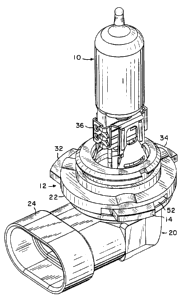
An example of a tamp assembly in accordance with the present
invention is shown in FIGS. 1-3. An electric lamp 10 is mounted in a lamp
base 12, which is shown separately in FIG.4. The lamp base 12 is utilized
for electrical connection to lamp 10 and for mechanical mounting of lamp 10
in a keyed lamp fixture such as a reflector. In addition, the lamp base
includes keying to ensure that the lamp assembly can only be installed in a
lamp fixture, such as a reflector, to which it is matched. The lamp assembly
further includes a movable key 14 as described below. The lamp assembly
shown in FIGS. 1-3 is similar to a type 9006 headlamp, but includes variable
keying in accordance with the present invention.
The lamp base 12 is typically molded of a high temperature plastic
and includes a lamp base body 20 having a key portion 22 and a connector
portion 24. The connector portion 24 is of conventional design and may
have a right angle configuration as shown in FIGS. 1-4. In other
embodiments, the connector portion of the lamp base may have a straight
configuration or any other suitable configuration. The key portion 22 of lamp
base body 20 may be generally circular in shape and have a central axis 30
that is coaxial with the central axis of electric lamp 10. Fixed keys 32 and
34
extend radially outwardly from lamp base body 20. Each of the fixed keys 32
and 34 is typically an integrally molded part of lamp base body 20 and may
have the form of a radially-extending tab or projection. The fixed keys 32
and 34 are located at different circumferential positions on the key portion
22
of lamp base body 20.
The lamp 10 may be mounted in lamp base 12 using a conventional
mounting structure, including a metal clamp 36 that is secured to a press
seal portion of the lamp envelope. Contact pins of the lamp 10 extend into
the lamp base 12 and are electrically connected to conductors of connector
portion 24. The lamp 10 may, for example, be a quartz halogen lamp
capsule. However, different lamp types and different lamp mounting
structures may be utilized within the scope of the present invention.
The keying of the lamp base 12 is established by movable key 14 and
fixed keys 32 and 34. The keying parameters include the number of keys on
the lamp base 12, the angular spacing between keys with respect to central
axis 30, and the size and shape of each individual key. Each key is matched
as to size, shape and location with a corresponding notch or recess on the
2 ~~ss~ ~
lamp fixture in which the lamp assembly is to be installed. A lamp assembly
in accordance with the present invention includes at least one fixed key and
at least one movable key.
As best shown in FIG. 5, the movable key 14 is attached to a key
carrier 40, which provides a mechanical connection between movable key 14
and lamp base body 20. The key carrier 40 may comprise a split ring having
an opening 42, an inside surface 44 and a top surface 46. The movable key
14 is preferably formed on top surface 46 so that it is axially offset from
key
carrier 40. In a preferred embodiment, the movable key 14 and the key
carrier 40 are integrally molded of a high temperature plastic. The inside
surface 44 may have ratchet elements, such as ratchet teeth or flats, which
define discrete positions of the movable key 14.
As best shown in FIGS. 2 and 4, the key portion 22 of lamp base body
20 is provided with a generally circular surface 50 that is coaxial with axis
30.
The surface 50 may be axially offset from fixed keys 32 and 34 and may
have ratchet elements, such as ratchet teeth or flats. During manufacturing,
the key carrier 40 is snapped onto the lamp base body with its inside surface
44 engaging surface 50 of lamp base body 20. Portions 54 and 56 of lamp
base body 20 on opposite sides of surface 50 are larger in diameter than
surface 50, thus defining a groove in the lamp base body. The portions 54
and 56 axially locate the key carrier 40 with respect to the lamp base body.
The lamp base body may further include an opening 52 for receiving
movable key 14. The opening 52 is axially aligned with fixed keys 32 and
34. When the key carrier 40 is positioned on surface 50 of lamp base body
20, the movable key 14 is located in opening 52. Preferably, the opening 52
is dimensioned to limit the rotation of movable key 14 to a selected number
of possible positions of movable key 14. The opening 52 may be generally
arc shaped so as to define a range of rotation of movable key 14.
189~~ ~
-6-
As indicated, the inside surface 44 of key carrier 40 and the circular
surface 50 may have ratchet elements which define discrete positions of
movable key 14. The ratchet elements may be in the form of ratchet teeth,
flats or any other suitable ratchet configuration. In one embodiment, the
surface 50 has a six-degree spacing between adjacent ratchet elements as
shown in FIG. 3. The opening 52 limits the possible positions of movable
key 14 to six positions separated by six degrees. It will be understood that
different angular separations between key positions may be utilized, and
different numbers of key positions may be selected. The spacing between
adjacent key positions should be sufficient to prevent installation of the
lamp
assembly in the wrong lamp fixture. The number of key positions depends
on the number of lamp types that may be utilized in the lamp base.
After the key carrier 40 has been snapped onto the lamp base body
20 and rotated, if necessary, to the desired angular position, it is secured
in
position by an adhesive, heat staking, ultrasonic welding, or any other
suitable technique for attaching the parts together. For example, surface 60
of movable key 14 (FIG. 5) may be attached to surface 62 of lamp base body
20 (FIG. 4) adjacent to opening 52 by one of the above-described
techniques. The lamp assembly is thereby permanently keyed and may be
installed only in a reflector or other lamp fixture having a key configuration
that matches the keying of the lamp base. It will be understood that the
movable key 14 remains fixed in position after completion of manufacturing
so as to define a fixed key configuration.
Because the movable key 14 is movable between selected key
positions during manufacturing, a number of different lamp configurations
can be established with a single lamp base and movable key. Thus, molding
of multiple lamp base configurations is not required. Only two lamp base
parts must be stocked to produce multiple lamp base key configurations.
~~~~o ~
_,_
It will be understood that the movable key 14 and the fixed keys 32
and 34 may have different configurations within the scope of the present
invention. For example, the lamp assembly may include one or more fixed
keys and one or more movable keys. The key carrier 40 may have any
configuration that is suitable for attachment of the movable key to the lamp
base body. The movable key may have different sizes and shapes. Ratchet
elements are not necessarily required for defining discrete positions of the
movable key. The inside surface 44 of key carrier 40 and the circular
surface 50 of lamp base body 20 may be smooth, so that the movable key
may be continuously rotated within a prescribed angular range established
by opening 52.
In one application of the present invention, the lamp assembly is
utilized in a fog lamp for a vehicle. The lamp assembly is mounted in a
keyed fog lamp reflector. The keying of the lamp assembly may correspond
to different wattages. For example, the fog lamp may have multiple
wattages between 25 and 100 watts, each of which corresponds to a
different key configuration.
While there have been shown and described what are at present
considered the preferred embodiments of the present invention, it will be
obvious to those skilled in the art that various changes and modifications
may be made therein without departing from the scope of the invention as
defined by the appended claims.