Note: Descriptions are shown in the official language in which they were submitted.
Imo,</~~
MOUNTING DEVICE
The invention concerns a device for mounting and
keeping a submersible pump unit together.
A machine of this type normally comprises an
electrically driven motor and a hydraulic unit with a rotating
impeller connected to the motor via a driving shaft.
In order to prevent the medium within the hydraulic
part from penetrating the electric motor via the shaft, one or
several seals are arranged between the hydraulic part and the
motor. One common type of seal is the so-called mechanical
face seal which comprises one seal ring rotating with the shaft
and one stationary seal ring in the surrounding pump housing.
The two seal rings are pressed towards each other by help of
spring force thus preventing liquid from penetrating between
the rings.
In order to secure a sufficient sealing there are
normally two mechanical seals arranged in a seal housing
containing oil for lubricating and cooling of the seal surfaces.
In order to obtain a good cooling of the electric
motor, it is common to let the pumped medium, water, flow
through a cooling jacket surrounding the motor on its way
towards the outlet.
A pump unit of the above described type will thus
comprise an electric motor having a surrounding cooling jacket,
a seal housing and a pump housing connected via a rotating
driving shaft.
1
72432-101
CA 02190442 2000-09-29
72432-101
In order to keep the different parts in a package
there are several different solutions. By big machines it is
common to provide the different parts with flanges and attach
said flanges by help of bolts around the peripheries. By
smaller machines it is common to arrange a few long bolts
around the periphery which press the outer parts towards each
other, thus locking the intermediate part therebetween.
Solutions of the above described type are shown in SE
414 696 and DE 1653 726.
A disadvantage with the solutions described above is
that they are expensive as regards the material as well as the
necessary mounting time. It has therefore been desired to
obtain a construction that is inexpensive to manufacture and
easy to mount, especially for smaller pumps where the cost is
very important. This problem has been solved in an effective
way by help of the device according to the invention.
In summary, the present invention provides a device
for mounting and keeping the parts of a submersible pump unit
together, comprising in combination: an electric motor having a
rotor with a shaft, and a stator, and stator housing surrounded
by a cooling jacket; a pump housing having an impeller coupled
to said shaft, and a seal housing positioned between said
stator housing and said pump housing; a first group of screw
joints and a second group of screw joints being, alternately
arranged around the periphery of the pump unit proximate said
seal housing; a ring being arranged around the seal housing to
enable said first group of screw joints to maintain said stator
housing and said seal housing together; said second group of
screw joints maintaining together said ring, said pump housing,
and an end of the cooling jacket that abuts the pump housing;
2
CA 02190442 2000-09-29
72432-101
and said stator housing having outwardly directed ears which
cooperatively engage said first group of screw joints.
The invention is described more closely below with
reference to the enclosed drawings.
Fig. 1 shows a cut through a pump mounted according
to the invention. Figs. 2 and 3 show enlarged details of the
pump in two differently by turned cuts.
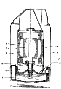
In the drawings 1 and 2 stand for the rotor and the
stator respectively in an electric motor. 3 stands for a
driving shaft, 4 a seal housing, 5 a pump housing with impeller
6, 7 a cooling channel, 8 a stator housing, 9 a flange or ear
on the stator housing, 10 a cooling jacket, 11 an edge
2a
.~ ~~qo yy~
folding on the jacket 10, 12 the bottom of the oil housing,
13 and 14 rings, 15 and 16 screw joints and 17 a hole in the
pump housing 1.
As previously mentioned the pump unit comprises the
three main parts motor, seal housing and pump housing which
are kept together in a simple and secure way which is also
easy to mount.
According to the invention two groups of screw joints
15 and 16 respectively are used, which joints are arranged
alternatively around the periphery of the pump unit on a level
with the seal housing 4. The number of joints may vary but at
least three of each group is to prefer in order to obtain a
sufficient security.
The joints 15 in one of the groups join a number of
lugs 9, which extend outwards from the lower edge of the stator
housing 8 and a ring 13 arranged under a flange on the bottom
12 of the seal housing 4. In this way the stator housing 8
and the seal housing are connected to each other.
The joints 16 in the other group of joints join said
ring 13 and an edge folding 11 on the end of the cooling jacket
10 heading the pump housing 5 via an additional ring 14. Said
two rings 13 and 14 are now fixed relative each other. As the
ring 13 abuts the seal housing 4 on the under side and the ring
14 abuts the edge folding 11 on the upper side, the consequence
is that the motor and seal housing are rigidly attached to each
other.
3
72432-101
-- . ~ ~ ~ o, ~~i~
Finally the joints 16 in the second group of joints
are arranged in a conventional way in holes 17 along the
periphery of the pump housing 5 an thereby all parts, motor,
seal housing and pump housing are attached to each other.
By help of the invention a very simple reliable and
a easy-to mount connection of the main parts in a pump unit is
obtained. Demounting is correspondingly easy.
4
72432-101