Language selection

Search

Patent 2190530 Summary

Third-party information liability

Some of the information on this Web page has been provided by external sources. The Government of Canada is not responsible for the accuracy, reliability or currency of the information supplied by external sources. Users wishing to rely upon this information should consult directly with the source of the information. Content provided by external sources is not subject to official languages, privacy and accessibility requirements.

Claims and Abstract availability

Any discrepancies in the text and image of the Claims and Abstract are due to differing posting times. Text of the Claims and Abstract are posted:

  • At the time the application is open to public inspection;
  • At the time of issue of the patent (grant).
(12) Patent: (11) CA 2190530
(54) English Title: ELECTROPHYSIOLOGY DEVICE
(54) French Title: APPAREIL D'ELECTROPHYSIOLOGIQUE
Status: Deemed expired
Bibliographic Data
(51) International Patent Classification (IPC):
  • A61N 1/40 (2006.01)
  • A61B 18/14 (2006.01)
  • A61N 1/04 (2006.01)
  • A61B 18/00 (2006.01)
(72) Inventors :
  • LA FONTAINE, DANIEL MARC (United States of America)
(73) Owners :
  • BOSTON SCIENTIFIC LIMITED (Barbados)
(71) Applicants :
  • SCIMED LIFE SYSTEMS, INC. (United States of America)
(74) Agent: ROBIC
(74) Associate agent:
(45) Issued: 2007-03-27
(86) PCT Filing Date: 1995-06-14
(87) Open to Public Inspection: 1995-12-21
Examination requested: 2002-05-08
Availability of licence: N/A
(25) Language of filing: English

Patent Cooperation Treaty (PCT): Yes
(86) PCT Filing Number: PCT/US1995/007576
(87) International Publication Number: WO1995/034346
(85) National Entry: 1996-11-15

(30) Application Priority Data:
Application No. Country/Territory Date
08/259,663 United States of America 1994-06-14

Abstracts

English Abstract


An ablation and mapping catheter is disclosed which incorporates a fluid electrode for contacting tissue. The fluid emerges along the
length of the catheter to generate a linear lesion in the cardiac tissue.


French Abstract

Cathéter d'ablation et de cartographie comprenant une électrode à fluide pour toucher les tissus. Le fluide sort le long du cathéter pour produire une lésion linéaire dans les tissus cardiaques.

Claims

Note: Claims are shown in the official language in which they were submitted.


6


WHAT IS CLAIMED IS:

1. An electrophysiology device for treating tissue by energy
delivered from an energy source, comprising:
an elongate catheter body (25) having a lumen (27) for carrying
fluid and having a distal end (31) and a proximal end (33), said catheter body
(25) having an axis (36);
at least one electrode site (18) located proximate said distal end
(31);
at least one wire (37) for connection to said at least one electrode
site (18) and to said energy source (20);
a plurality of apertures (29) extending along said axis (36) and
communicating with said lumen (27);
a source (24) of electrolyte fluid (54) in fluid communication with
said lumen (27);
wherein energy from said energy source (24) is directed by said at
least one wire (37) from said energy source (20) to said at least one
electrode
site (18), and energy is coupled to said electrolyte fluid (54) at said at
least one
electrode site (18) and communicated to said tissue through said plurality of
apertures (29) to create at least one linear lesion.
2. The electrophysiology device of claim 1 further comprising a
porous sheath (34) covering said plurality of apertures (29) for permitting
the exit
of fluid from said lumen (27).
3. The electrophysiology device of claim 1 or 2, wherein said at
least one electrode site (18) comprises a plurality of electrode sites.
4. The electrophysiology device of claim 1 or 2, wherein said
distal end (31) is closed.


7


5. The electrophysiology device of claim 1 or 2, wherein each
of said plurality of apertures (29) is perpendicular to said axis (36).
6. The electrophysiology device of claim 3, further comprising
a plurality of wires (37) respectively connected between said plurality of
electrode sites (18) and said energy source (24), so that said electrode sites
(18) are independently accessible.
7. The electrophysiology device of claim 1 or 2, wherein the
plurality of apertures (29) is aligned.

Description

Note: Descriptions are shown in the official language in which they were submitted.


CA 02190530 2005-O1-20
1
ELECTROPHYSIOLOGY DEVICE
1. Field of the Invention
The present invention related to
electrophysiology and more particularly to a device and
method of operation for an ablation instrument.
2. Backaround Art
Arrhythmias can be treated in a number of
ways. The traditional treatment has been the systemic
administration of anti-arrythmia drugs. However there
is a narrow difference between a therapeutic dose and a
toxic dose of the most effective drugs. In many
instances the drugs induce bradycardia and the patient
may receive a heart pacemaker to treat this induced
condition.
Another approach is to treat the arrythmia
with electrical stimulation of the ventricle to
interrupt the arrythmia and convert the heart to normal
sinus rhythm. This process may be performed with an
implanted device.
A third approach is ablation. Many
arrhythmias result from accessory electrical pathways
which participate in the generation and continuation of
tacky-arrhythmias. It is possible to destroy these
accessory pathways by selectively ablating the offending
tissue. The application of heat or other energy
disrupts and injures the tissue and slows down or
prevents the conduction of electrical impulses. The
principle benefits of ablation therapies flow from the
fact that no implantable device is required nor is a

CA 02190530 2005-O1-20
2
prolonged and expensive drug therapy =aa~ui=-ed. Thus the
patient experiences an improved qualify of =ife at a
educed overall cost.
The principal problems related to ablation
stem from the requirement to localize the conduction
disturbances and then to deliver the ablation energy to
the same selected conduction site. This is exceedingly
difficult to do given the constant motion of the heart.
The energy densities used for radio-frequency ablation
are sufficient to "boil" the blood and cause tissue to
adhere to the catheter tip. Therefore these therapies
must be delivered with care. Therefore there exists a
continuing need to improve the ability to deliver
ablation energy to heart tissue.
SUMMARY
The present invention is a catheter system
that can be used for contact mapping and for the
delivery of radio-frequency energy along a segment of
the catheter which forms a "linear" lesion in the
tissue. The catheter relies on a fluid electrode to
conduct the RF energy to the tissue. The fluid
electrode is preferably a normal saline solution
delivered from a pump or the like under the control of
the physician. A porus dielectric surface helps to
direct the fluid electrode into contact with the tissue.
More specifically, the invention is concerned with an
electrophysiology device for treating tissue by energy delivered from an
energy
source, comprising:
an elongate catheter body having a lumen for carrying fluid and
having a distal end and a proximal end, said catheter body having an axis;
at least one electrode site located proximate said distal end;
at least one wire for connection to said at least one electrode site
18 and to said energy source;

CA 02190530 2005-O1-20
2a
a plurality of apertures extending along said axis and
communicating with said lumen;
a source of electrolyte fluid in fluid communication with said lumen;
wherein energy from said energy source is directed by said at least
one wire from said energy source to said at least one electrode site, and
energy
is coupled to said electrolyte fluid at said at least one electrode site and
communicated to said tissue through said plurality of apertures to create at
least
one linear lesion.
BRIEF DESCRIPTION OF THE DRAWINGS
The various figures of the drawing set forth
an illustrative and exemplary form of the invention.
Throughout the various figures identical reference
numerals refer to identical structures, wherein:
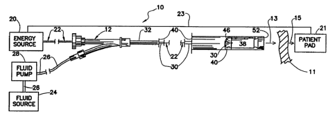
FIG. 1 is a view of the invention with the
distal tip enlarged to clarify certain details of
construction;
FIG. 2 is an enlarged view of the distal
portion of the invention;

CA 02190530 2005-O1-20
3
FIG. 3 is a view of an alternative embodiment
of the invention.
DETAILED DESCRIPTION OF THE INVENTION
FIG. 1 shows the electrophysiology device 10
as part of system. The system includes an energy source
20, a fluid pump 28 coupled to a fluid source 24 through
an appropriate tube 26. The fluid pump 28 draws fluid
from the fluid source and forces fluid through the
central fluid lumen 40 of the catheter 32_ A Y-shaped
manifold 12 couples the energy source 20 and the fluid
system to the catheter 32.
The energy source 20 is coupled to the
electrode 38 through a wire 22. This wire 22 passes
through a sheath 30 and terminates at a connection 50
located on an electrode 38. The RF energy exits the
distal open end 52 of the catheter 32 and passes through
the heart tissue 11 as indicated by arrow 13. RF
current passing through the heart tissue 11 is collected
at the exterior of the patient through a patient pad 21
and is returned to the energy source 20 through return
path wire 23 completing the electrical circuit.
Experimental work has been performed with an energy
source delivering approximately 50 Watts of power
delivered into 100 Ohms at about 500 Ki~iz.
The RF energy is confined and directed by a
fluid f lowing through the fluid lumen 40 of catheter 32
tube. In general, a reservoir or fluid source 24 is
provided to store an electrolyte fluid shown in the
figure by arrow 54. In practice the electrolyte is a
saline solution formed by the addition of 35 G of NaCl
to 100 ml of water. This balanced saline works well but
higher ionic concentrations may be more effective for
some applications where the additional salinity is well
tolerated. A modest flow of electrolyte 54 is induced
by pump 28 to direct fluid flow against the cardiac
tissue 11. In use, the moving saline forms a fluid

CA 02190530 2005-O1-20
4
electrode to assist in the delivery c. energy to the
tissue 11.
FIG. 2 shows a detail of the distal end of the
catheter 32. The drawing shows that the fluid 54
receives the RF energy by passing over the interior of
electrode 38. This electrode 38 is located a short
distance from the open end 52 of the catheter 32. In
general, it is desirable to have a short.path length
from the electrode 38 to the tissue 11. But it is also
desirable to locate the electrode 38 a sufficient
distance from the tissue 11 to prevent adhesions and the
like from contaminating the surface of the electrode 38.
The catheter shown in FIG. 2 is particularly effective
in making relatively isolated lesions in part because
the fluid exits the catheter "axially" at the very
distal tip of the catheter 32 body.
FIG. 3 shows a catheter 16 that is adapted to
generate a "linear" lesion 14 which extends along the
length of the active zone 15 of the catheter 16. In
this construction a number of electrodes typified by
electrode 18 are aligned along the length of the
catheter body 25. The electrodes are coupled to the
energy source or other switching structures through
wires typified by wire 37. The catheter body 25 has an
axis 36. The central lumen 27 of the catheter body 25
is coupled to the fluid source 28 (not shown). The
fluid as it moves into the active zone 15 connects to
the energy source 20 (not shown) and exits from the
catheter body 25 "radially" by migrating through several
holes typified by hole 29. A porous sheath 34 overlays
the hole pattern and helps to regulate the passage of
fluid from the lumen 27. The porus sheath 34 places a
porus surface proximate the tissue 11. The multiple
electrode sites permit the catheter to be quite flexible
over the length of the distal segment. If each
electrode set is independently accessible through
separate connections for mapping studies then the

219~~~p
WO 95134346 PCTlUS95107576
catheter 16 may be used.for mapping when the central
lumen 27 is filled with-a dielectric fluid. Once the
ectopic-site-has been located the central lumen may be
quickly filled with the non-dielectric, electrolyte
5 saline solution to perform ablation. In general, the
presence of. saline in the lumen will partially 'short"
out the electrodes and during ablation the electrode
will be connected-in parallel to carry the RF currents.
It is also possible to use the individual sets of
electrodes to "focus' energy along the length of the
active zone-even in the presence of saline, especially
if-the salt concentration is low. It should be
appreciated that if dielectric tubas were provided to-
each electrode site then multiple spot ablation could be
performed at selected sites. However, it is believed
that the ability to generate a linear connected lesion
will prove more effective at removing accessory
pathways.
SUBSTITUTE SHEET (RULE 26)

Representative Drawing
A single figure which represents the drawing illustrating the invention.
Administrative Status

For a clearer understanding of the status of the application/patent presented on this page, the site Disclaimer , as well as the definitions for Patent , Administrative Status , Maintenance Fee  and Payment History  should be consulted.

Administrative Status

Title Date
Forecasted Issue Date 2007-03-27
(86) PCT Filing Date 1995-06-14
(87) PCT Publication Date 1995-12-21
(85) National Entry 1996-11-15
Examination Requested 2002-05-08
(45) Issued 2007-03-27
Deemed Expired 2012-06-14

Abandonment History

Abandonment Date Reason Reinstatement Date
1999-06-14 FAILURE TO PAY APPLICATION MAINTENANCE FEE 2000-04-06
2005-01-06 R30(2) - Failure to Respond 2005-01-20
2005-01-06 R29 - Failure to Respond 2005-05-26

Payment History

Fee Type Anniversary Year Due Date Amount Paid Paid Date
Application Fee $0.00 1996-11-15
Registration of a document - section 124 $0.00 1997-02-20
Maintenance Fee - Application - New Act 2 1997-06-16 $100.00 1997-06-03
Maintenance Fee - Application - New Act 3 1998-06-15 $100.00 1998-06-01
Reinstatement: Failure to Pay Application Maintenance Fees $200.00 2000-04-06
Maintenance Fee - Application - New Act 4 1999-06-14 $100.00 2000-04-06
Maintenance Fee - Application - New Act 5 2000-06-14 $150.00 2000-05-04
Maintenance Fee - Application - New Act 6 2001-06-14 $150.00 2001-04-04
Maintenance Fee - Application - New Act 7 2002-06-14 $150.00 2002-04-02
Request for Examination $400.00 2002-05-08
Maintenance Fee - Application - New Act 8 2003-06-16 $150.00 2003-04-03
Maintenance Fee - Application - New Act 9 2004-06-14 $200.00 2004-03-24
Registration of a document - section 124 $100.00 2004-11-25
Reinstatement - failure to respond to examiners report $200.00 2005-01-20
Maintenance Fee - Application - New Act 10 2005-06-14 $250.00 2005-03-29
Reinstatement for Section 85 (Foreign Application and Prior Art) $200.00 2005-05-26
Maintenance Fee - Application - New Act 11 2006-06-14 $250.00 2006-03-24
Final Fee $300.00 2007-01-08
Maintenance Fee - Patent - New Act 12 2007-06-14 $250.00 2007-03-20
Maintenance Fee - Patent - New Act 13 2008-06-16 $250.00 2008-05-07
Maintenance Fee - Patent - New Act 14 2009-06-15 $250.00 2009-05-07
Maintenance Fee - Patent - New Act 15 2010-06-14 $450.00 2010-05-07
Owners on Record

Note: Records showing the ownership history in alphabetical order.

Current Owners on Record
BOSTON SCIENTIFIC LIMITED
Past Owners on Record
LA FONTAINE, DANIEL MARC
SCIMED LIFE SYSTEMS, INC.
Past Owners that do not appear in the "Owners on Record" listing will appear in other documentation within the application.
Documents

To view selected files, please enter reCAPTCHA code :


To view images, click a link in the Document Description column. To download the documents, select one or more checkboxes in the first column and then click the "Download Selected in PDF format (Zip Archive)" or the "Download Selected as Single PDF" button.

List of published and non-published patent-specific documents on the CPD .

If you have any difficulty accessing content, you can call the Client Service Centre at 1-866-997-1936 or send them an e-mail at CIPO Client Service Centre.


Document
Description 
Date
(yyyy-mm-dd) 
Number of pages   Size of Image (KB) 
Representative Drawing 1997-12-03 1 5
Claims 2005-01-20 2 46
Description 2005-01-20 6 206
Cover Page 1995-06-14 1 11
Abstract 1995-06-14 1 26
Description 1995-06-14 5 150
Claims 1995-06-14 1 27
Drawings 1995-06-14 2 29
Abstract 2007-03-26 1 26
Drawings 2007-03-26 2 29
Description 2007-03-26 6 206
Representative Drawing 2006-04-25 1 7
Cover Page 2007-02-28 1 32
Correspondence 2007-01-08 1 39
Assignment 1996-11-15 10 392
PCT 1996-11-15 10 396
Prosecution-Amendment 2002-05-08 1 37
Fees 2000-05-04 1 31
Prosecution-Amendment 2004-07-06 4 159
Assignment 2004-11-25 4 123
Correspondence 2005-01-17 1 13
Prosecution-Amendment 2005-01-20 10 313
Prosecution-Amendment 2005-05-26 2 31
Prosecution Correspondence 2002-05-17 1 37
Correspondence 2011-07-26 1 81
Correspondence 2010-08-10 1 47