Note: Descriptions are shown in the official language in which they were submitted.
W09~/30884 2 ~ 9~6 1 2 ~ 112
APPARATUS AND METHOD FOR MEASURING M_qC FLOW RATE
Ba.ih4L~ An-9 summarY of rhP Inven~ion
The present invention relates to an arrangement for
the contactless mea- uL~ L of the ~ Ct:~lLLa~iOn and the
derivation of a mass f low rate of a moving material . More
particularly, the present invention relates to an
aLLall, L for the contactless measurement of a ma66 flow
rate of a material moving through an ele~ LL _ Lic field
of known fre~uency and power ba6ed upon the magnitude of
the electromagnetic energy reflected by the material a6 it
pa66e6 through the f ield and the velocity of the material .
Di6turbance 6en60rs that utilize an ele~;Lr~ --jnPtic
6ignal of known frequency to dttpnm; I-P the velocity,
di6tance, or pre6ence of a moving ta~get object are known.
Example6 of 60me more well known di6turbance 6en60r6
include tho6e u6ed in police and aircraft radar6. The6e
6en60r6 rely on a change or shift between the fre~uency of
~n ele.;LL ~--etic 6ignal tran6mitted from the 6en60r and
the frequency of that portion of the signal which i8
reflected by the moving target object. Thi6 change or
6hift in the freyuency of a tran6mitted and reflected
elel LL, -t;c 6ignal i6 referred to as a Doppler shift.
An example of 6uch a change or 6hift that i6 detectable at
audible fre~uencie6 occur6 when an audible 60urce i6 active
and moving relative to a per60n. The 60und pitch i6
perceived to increa6e when the audible 60urce i6 moving
toward the per60n and to decrea6e when the audible 60urce
i6 moving away from the per60n. The magnitude of thi6
LLe~U~ Y 6hift or change i6 proportional to the velocity
of the moving object.
The pre6ent invention establishes that the
c~.,LL~tion of a moving material can be measured based
upon the amount of electromagnetic energy or power
reflected by the material when it passes through a field of
W0 95/30884 ~ ~ q o ,~; 2 ~ 412
ele~;LL, ~n-~tic energy of known power. Applicant has
observed that a6 the au..a~ L.,t.ion of a material increases,
the magnitude of ele~LL~ ?tiC energy that i5 reflected
by the material also increases. The present invention
5 further estAhl;ch~c that the flow rate of a material ~oving
past a point can be determined by multiplying the mass of
the material moving pa6t the point by the velocity of the
material. The mass, in turn, is equal to the volume of the
material and air ill~ nAted by the field divided by the
10 c.,..ce..LL~,tion of the material.
The present invention _ i n~q the magnitude of
elecL. _ ?tiC energy reflected from a moving material
with the Doppler shift rLeUUt~ to produce a response
related to the mass f low rate of the material . The
15 invention sl~hcPqll~ntly utilizes this response along with
user-supplied data relating to a particular material
process flow to generate a linearized response related to
the mass f low rate of the material.
Current mass f low rate meters that have sensors, such
20 as antennas and impact plates, which are placed in a
material process f low path have several disadvantages .
Over time, material can build up on these intrusive sensor6
which impairs meter sensitivity. Also, such sensors
require frequent adjustment because continual and repeated
25 material impact eventually moves them out of calibration.
In addition, moving material can impact an intrusive sensor
in such a way that it is damaged and in need of repair or
replacement. Furthermore, intrusive sensors are subject to
changes in amhient conditions within a material process
30 flow, such as temperature and humidity, which requires that
a meter be recalibrated to the new ambient conditions or
that the conditions of the material process f low be
carefully monitored and adjusted. Finally, impact sensors
can damage the material in a process f low .
WO 95/30884 ~ C5412
21906l2
The pre6ent invention addresses the above-described
problems associated with intrusive mass rlow rate meters by
providing a contactless ( i . e ., non-intrusive) mass f low
r~te meter . The contactless mass f low meter of the present
5 invention includes a transceiver that transmits an
elecLL , ~ ic signal of known frequency and power across
a material process f low . The transceiver detects the
magnitude and ~oppler shift of the ele~LL _ ?t; r~ signal
that is ref lected by material moving along the process f low
10 as it passes through an ele.LL ~nP~ic field e5t:~hl;F:h~l
by the signal . The transceiver then h; nP~e the magnitude
of the rPf 1 P~tpd elt:ULLI , tic signal along with the
Doppler shift between the frequency of the transmitted and
reflected ele~:LL , -tic signais to generate an output
15 signal related to the mass flow rate of the material. This
signal has a magnitude substantially equal to the magnitude
of the reflected ele-,LL ~nPtic energy and a frequency
substantially equal to the difference between the frequency
of the transmitted and reflected electromagnetic signals.
20 This signal may be linear or non-linear.
The present invention further includes an amplif ier
electrically associated with the transceiver to amplify the
transceiver output signal to a prP~lP~Prm;npd level for a
predetermined rL~uuen~ y range so tha~ the signal may be
25 further l Luces6ed. A user interface of the present
invention allows the mass flow meter to be set up and
calibrated for a particular material process flow as well
as adjusted over time. A central processing unit of the
present invention calculates a linea~ized output signal
3 0 representative of the mass f low rate of the material, which
is based upon the user supplied set-up, calibration, and
adju~i L data and the amplified transceiver output
signal. The central processing unit then converts this
linearized signal into a digital r~yL~sentation of the mass
35 flow rate of the material. Circuitry of the present
Wo 9s/30884 I ~~ 41~
21 90612
invention ~u~ uue,-c.e6 the digital central proc~c; nq unit
output signal to gener~te a signal related to the mass flow
rate of the material.
In a preferred i L of the present invention,
5 the digital central processing unit output signal is a
pulse width modulated signal. The pulse width of this
signal is related to the mass f low rate of the material
such that the width of the signal increases with increased
material flow rate. A circuit of this preferred . : ;- L
10 converts the pulse width modulated signal into an analog
current signal that is substantially linear through the
range of mass f low rates . The magnitude of this current
signal is related to the pulse width modulated signal such
that the larger the width of the pulse, the higher the
15 magnitude of the current signal.
In the same preferred P~hor1i L, the central
processing unit generates two output signals, one of which
is indicative of the condition where the mass f low rate is
below a user predef ined minimum level and the other of
20 which is indicative of the condition where the mass flow
rate is above a user predef ined maximum level .
The above-described user interface ûf the present
invention allow6 the mass f low meter to be calibrated to
the particular characteristics of a material process flow.
25 The user interface of a preferred c '~ allows the
ampli~ication or sensitivity of the meter to be adjusted
for a particular material process flow so that optimum
amplif ier gain occurs during maximum f low rate of the
material. To achieve optimum gain, the gain of the
30 amplifier may have to be adjusted up or down tlPpPn~ling upon
the characteristics of a particular process f low . The user
interface of this preferred '-'i-- L also allows
calibration points to be set at various material flow rates
80 that the central processing unit can linearize the
35 amplified transceiver output signal using interpolation
WO 9513O884 1~ . 112
2~6~
techniques. The user interface of t~is preferred
~ ~ ~i t, further allows a user to Pdjust the size of a
central proces6ing unit buffer that receives and stores
amplified transceiver output process flow signals.
5 Increasing the size of this buffer ircreases the numoer of
amplified transceiver output process flow signals that are
used by the central procPccing unit to generate a
linearized signal ~ Lc~ lLative of the mass flow rate of
the material. The user interface of this preferred
lO PmhOAi ~ also allows the above-described minimum and
maximum mass flow rates to be set an~ changed for those
PmhOA i ~5 of the meter of the present invention which
generate these signals. Finally, the user interface
provides status information that allows a process flow to
15 be monitored.
Other objects, advantages and novel features of the
present invention will become apparent from the following
APt5. i 1 P~l description of the invention when considered in
conjunction with the a _-nying drawings.
Brief Descri~tion of the Drawin~s
Figs . la-lc illustrate a mass f low rate meter of the
present invention transmitting an energy signal across a
material flow path and receiving electrical magnetic energy
25 which is ref lected by material moving in the f low path, the
quantity of which is shown increasing with increased
material c.,..~:..LL~ltion.
Fig. 2 illustrates a preferred setup for the meter of
the present invention adjacent a material flow path.
Fig. 3 is a block diagram of a preferred P~hoA; ~ of
the electrical circuitry of the mass f low rate meter of the
present invention.
Figs. 4a and 4b are circuit schematics of a preferred
pmhoAi-- L of a multi-stage amplifie~ and low pass filter
of the present invention.
W09s/30884 r~l,.J.. ~4l2
21 9061 2
Figs. 5a and 5b are circuit schematics of a preferred
~mho~l;r L of a central processing unit stage of the
present invention.
Figs. 6a-1, 6a-2, and 6b-1 and 6b-2 show flow charts
of a preferred ' '; ~ of 60ftware of the present
invention used to program and control a central proce6sing
unit stage of the present invention.
Figs. 7a-7d show preferred ~ Ls of a
keypad/control panel of a user interface of the present
invention used to set up, calibrate, and adjust the mass
flow rate meter of the present invention for different
mnterial process f lows .
Figs. 8a and 8b are circuit schematics of a preferred
~ ' ~;r ~ of the keypad/control panel of the user
interfnce of the present invention.
Figs. 9a and 9b are schematics of a preferred
p~horl; L of a circuit for controlling relay outputs of
the mas6 f low meter of the present invention .
Figs. lOa and lOb are circuit schematics of a
preferred ~-~o';---L of an analog current output circuit of
the mass f low rate meter of the present invention .
I:etailed Description of the Drawinqs
The pre6ent invention est~hl; ~:hPC that the
c~ ,L,~,Lion of a material can be measured based upon the
magnitude of ele~:L, -qnPtic energy or power reflected from
n material when passing through a field of ele~LL, ~netic
energy of known power . The power ref lected from a target
material can be approximated by the following expression:
PR = PO + 2GA", + Gr -- s2
where
PR ~ Power reflected from the material
P0 = Transmitted power
G,~," = Antenna gain
GT = Equivalent target gain
WO95/30884 2 1 q06 1 2 . .,.,~ 412
S = 2 way ~LU~Iy~tiOn loss in free space
The power reflected from a material 'IPR'' increase6 with the
equivalent target gain 'IGT", ACC.-m;nq all other factors in
the equation are constant. The equivalent target gain ~GT~
is directly ~rPn-lPnt upon the reflectivity and cross-
sectional area of the target material. For a given
material, the cross-sectional area increases with increased
material ~ VlI~ el:LL~tiOn. Therefore, the reflected power
increases wlth increased material cc,llce.,LL~-tion. This
relationship is illustrated in Figs. la-lc.
Fig . la shows a mass f low rate meter 10 of the present
invention mounted adjacent a material flow path 12. Meter
10 is mounted outside of flow path 12 50 that no material
flowing through flow path 12 contacts meter 10. A
tran6ceiver (not shown) of meter 10 transmits
ele~ ~L ~nPtic energy signals 14 of known power and
frequency 50 as to generate a field across material flow
path 12 . Fig . lb shows process f low 16 of material 18
moving along flow path 12 and across the ele~LL ~nPt;c
field es~hlich~ by signals 14. A first quantity of
ele.:LL Lic energy 20 is reflected by material 18.
Ele.;LL, ~nPtic energy 20 represents only the Doppler
shifted energy (tlicCIlcc~ below~ reflected by moving
material 18 and not any energy reflected by, for example,
flow path 12. Only reflected energy 20 i6 important
because the ~o~lce~,LL~ltion of the material is related to
this value. Fig . lc shows a process f low 22 of material 18
moving along flow path 12 and across the ele- L. Lic
field est~hl ichPd by signals 14. A second quantity of
ele~LL gnPtjc energy 24 is reflected by material 18.
EleuLL Lic energy 24 also represents only the Doppler
shifted energy reflected by the moving material 18. The
- magnitude of energy 24 is also related to the cul. el-LL~tion
of material 18. As can be seen by comparing Figs. lb and
lc, the ~U~ICel-LLc-tion of material 18 ~5 greater for process
W09s/30884 r~.,L.. -~12
21906~2
flow 22 in Fig. lc than for proce6s flow 16 in Fig. lb. As
can also be seen by comparing Figs. lb and lc, this greater
cu~ ..LL,ltion re6ults in second quantity of ele.:L~ _ ^tiC
energy 24 being larger than first guantity of reflected
5 elecLL ; c energy 20.
The present invention further est~hl; C:hP5 that the
flow rate of a material moving past a point can be
determined by multiplying the mass of the materi~l moving
past that point by the velocity of the material.
10 Nathematically, the relationship can be expressed as
f ollows:
Q = Mass x V
where
Q = Material f low rate
Mass = The guantity or amount of material
V = The material velocity
The mass of the material can be determined based upon the
volume of air and material illuminated by a transmitted
electromagnetic energy signal divided by the concentration
20 of the material. Mathematically, the relationship can be
expressed as follows:
Mass = Vol,
where
Mass = The quantity or amount of material
Vol. = The volume of air and material
m;n:~ted by an ele~L ~nptic
energy signal
C = The l ol~ct:llLL~tion of material
The two immediately preceding equations can be combined to
derive the following relationship:
Q = Vol. x V
C
As discussed above, the concentration of a moving material
is related to, and can be determined from, the magnitude of
-
WO 95130884 ~ -412
219~612
ele~ LL gn~tic energy reflected by the moving material as
it passes through a field of ele~.L,, ~n~tiC energy. For a
given proceEi6 flow, the volume of air and material
illuminated by an ele~ LL~ ~n~tic energy signal is constant
5 although the ratio of each that combine to def ine the
volume may change.
When ele~LL _ ?tiC energy is reflected by a moving
target or material, a shift in the LLe~ut~ y of
ele~.LL, - Lic energy reflected from the moving target or
10 material occur6. This change in fre~uency is referred to
as a Doppler shift. The magnitude of the frequency shift
is proportional to the velocity of the material. Doppler
shift frequency is mathematically expressed as:
F = 2V(f/c) x cos(theta)
15 where
F = The Doppler shift freguency
V = The material velocity
f = The transmitted frequency of the
ele. ~L -7netic signal
c = The speed of light
theta ( 0 ) = The angle between the transmitted
elecLL -_ ?tiC energy signal and the
f low path of the material .
The above equation can be algebraically l~~nlr~lAted to
25 solve for the material velocity. The resulting equation
is:
V= F
2(flc) x co6(theta)
The above equations can be algebraically combined to
derive the folLowing relationship:
Q = Vol x F/[2(flc) x c~s(thet~)]
WO ~i/30884 ~ 112
.
21 ~361 2
This relationship i6 u~ed by the present invention to
determine the mass f low rate of a material through
process f low .
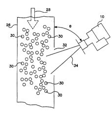
Fig. 2 shows meter 10 of the present invention mounted
adjacent a material flow path 26 through which a process
flow 28 of material 30 moves. Material flow path 26
includes a window 32 through which transmitted
elec~L ;~nPtic signal 34 passes to illllt~tinJ~te a portion of
moving material 30. Window 32 must have a n~ -luctive
surface in order for 6ignal 34 to penetrate it and
lllllt~t1n~te material 30. Suitable materials for window 32
include non-leaded gla6s and plastic. Window 32 may also
be an opening in flow path 26 as shown in Fig. 2.
Meter 10 is preferably mounted adjacent flow path 26
50 as to r-Y;t~ti7e the amount of Doppler 6hift. This i6
achieved by mounting meter 10 at an angle theta ( ~ ),
di6cu6sed above and shown in Fig . 2, with respect to f low
path 26. The preferred number of degrees for the angle ~
has been determined to lie in the range of approximately 25
2 0 to 4 5 degrees .
Fig. 3 is a block diagram of a preferred Prho~l;r ~ of
the mass f low rate meter 10 of the present invention .
Meter 10 inrltl~qPR a transceiver stage 36, an amplifier
stage 38, a central processing unit stage 40, and an output
stage 42.
Transceiver stage 36 includes an antenna 44 and a
transceiver 4 6 . Transceiver 4 6 transmits an
ele~:~L _ ~ic energy signal of known power and frequency
via antenna 44 to create a field of ele.:~L , ' ;c energy
across a material flow path through which the material
passes. Antenna 44 also detects and transmits
Qle.,~L _ -tic energy signals reflected from target
material passing through the field to transceiver 46.
Transceiver 46 ~L~,~_e5ses this reflected signal along with
the Doppler shift in frequencies between the transmitted
WO 95~0884 P~~ 412
219~612
11
and reflected ele.;~L, ~n~f j~. energy signals and outputs a
signal having a magnitude directly proportional to the
magnitude of the reflected ele~L~ ~n~tic energy signal
~nd a frequency substantially equal to the difference
5 between the LL e~u~ y of the transmitted and ref lected
ele.:~L _ tic signals. This output signal is commonly
known in the art as the "difference output signal. " The
magnitude of this signal is in the micro- to millivolt
range .
Transceiver 46 can be made from discrete elements
including a transmitter, generally indicated by block 48, a
receiver, generally indicated by block 50, and a mixer 52.
Transmitter 46 transmits an ele~ LL, 7nPtic signal of a
known frequency and power via zntenna 44. The frequency of
this signal is controlled by oscillator 54. Receiver 50
uses antenna 44 to receive the ele~.L~, _ tic signals
reflected by the moving material and output a signal
proportional to the magnitude of thece signals. Receiver
50 may include a transducer for this purpose. Mixer 52
combines the transmitted and reflected signals to generate
a difference output signal having the characteristics
described above . In a pref erred ~ nt of transceiver
stage 36, antenna 44 is a 16 dB gain horn K band antenna
and transceiver 46 i3 a Gunn Diode transceiver manufactured
by Alpha Indu6tries under model number GO52870. Use of
antennas with higher gain than 16 dB is appropriate where
greater sensitivity is required.
Amplifier stage 38 filters and amplifies the
difference output signal of transceiver 46 to an
appropriate level so that the difference output signal can
be processed by central processing unit stage 40. In a
preferred ~rholl;r~nt~ amplifier stage 38 produces an output
signal in a range of between 0.5 to 6.0 volts (zero-to-
peak) that lies within a frequency range of between
35 approximately 0 to 15 kilollertz (kliz). Amplifier stage 38
wo 95/30884 F~./~x _ -112
21 9~6~ 2
12
1 nrl ll~qPC: low pas6 f ilter 58 with a nominal gain of
approximately 30 APCihi 1~ (dB) and a 3dB roll-off point of
approximately 15 kHz. Amplifier stage 38 further includes
~ multi-stage amplifier 56 with a ~ inP~ gain of between
5 approximately 4dB and 29dB and a bandwidth in exce6s of low
pa6s filter 58.
Figs. 4a and 4b show circuit schematics of a preferred
` 'ir L of amplifier stage 38. Amplifier stage 38
includes a low pass filter 58 that receives the difference
10 output 6ignal of transceiver 46 on line G~1. Multistage
amplif ier 56 ~ nrl~ a user ad~ustable cour6e gain
amplif ier 62 that provides a signal gain in a range of
approximately 3 to 26 dB and is electrically crnn~cted to
have a negative feedback. Manual switch 63 and analog
15 switch 67 allow the value of fee-lhark resistance u6ed in
amplifier 62 to be selectively changed. In the preferred
Pmho~1i L illustrated, switch 67 is made by Motorola under
model number MC14016. Amplifier 56 also includes a user
adju6table fine gain amplifier 64 that provides a signal
20 gain in a range of approximately 1 to 3dB and is
electrically connected to have a negative feedback.
Potentiometer 65 allows the value of feedback resistance to
be selectively changed through a range of resistance
values. Multi-stage amplifier 56 further includes a 50/60
25 Hertz (Hz) notch filter 60 between amplifier 62 and
amplifier 64 that attenuates residual power line noise. In
the preferred Pmhor1i--- t illustrated, notch filter 60 is
made by National Semiconductor under model number LMF90.
Signal rectifier 66 of multi-stage amplifier 56
30 CUIIV~:LL~ the AC signal output of amplifier 64 to a dc
signal. Rectifier 66 provides an easy means of deriving
the magnitude of the output signal of amplifier 64 without
having to use signal processing techniques and a central
processing unit. The output of rectifier 66 for constant
35 material velocities is inputted to central processing unit
WO95/30884 I~.IIIJ.. '. 1~2
21 9~612
13
stage 40 via line ANl. For time-varying material
velocities, the output of rectifier 66 is electrically
connected to buffer circuit 69. Buffer output line AN0 is
electrically ,ronne,rted to central proc~C6inr~ unit stage 40.
As shown in Pig. 3, central processing unit stage 40
inr~ .S an analog-to-digital converter 68 that converts
the amplified transceiver difference output signal on
either line ANl or AN0 into a digital format for use by
central pror~oc-in~ unit 70 (CPU). Central proce6sing unit
70 calculates a linearized output signal representative of,
the flow rate of the material. Central processing unit 70
uses the digitized transceiver difference output signal and
user 5l~rpl iPd setup and calibration data to calculate this
linearized signal. The user supplied setup and calibration
data is provided via user interface 72 and user interface
port logic module 74. User interface 72 of the present
invention allows mass f low rate meter 10 to be calibrated
based upon particular material process f low
characteristics. User interface 72 also provides status
information that allows a process flow to be monitored.
User interface port logic module 74 ~ronn~rtC user interface
72 to central processing unit 70.
Figs. 5a and 5b show schematics of a preferred
i- L of central processing unit stage 40 which
lnrl~ c a Motorola MC68HC16Zl pLOyL hle
mi.;L~,c~,.lLL~,ller. Although not shown in Fig. 5, this
yL hle mi.:L~,co-l-L~,ller includes analog-to-digital
converter 68, central pror~Cc;n~ unit 70, and user
interface port logic module 74 as well as a pulse width
modulated signal generator and relay control logic outputs
~; crl~oe^~ more fully below.
Central processing unit stage 40 of Fig. 5a also
1nrl~ c a power-up reset control 76 that provides a means
to control a reset function of central processing unit 70
35 upon power up. Central processing unit stage 40 also
W0 9s~3088~ J. 412
21 9061 2
14
;n~ a miL;Lucu~ uller power line reset chip 77. In
the preferred ~ L illustrated in Fig. Sa, chip 77 is
an undervoltage detector made by Motorola under model
number MC34064-5. A clock excitation circuit 78 provides a
5 clocking signal for central processing unit 70 of stage 40.
Program memory module 80 is an Erasable PLUU,L hle Read
Only Memory (EPROM) that stores a software program for
central proco#~in~ unit stage 40 ~ c-lccorl more fully
below. In the preferred orho~lir L illustrated in Fig. Sb,
10 module 80 is made by Nztional ~omicnn~ tor under model
number NM27C256. A resistor network 81 defines the
configuration of central processing unit 70 after power up.
Figs. 6a-1, 6a-2, 6b-1, and 6b-2 show a flow chart of
a preferred ~ ~ i L of the software of the present
15 invention used to program centrcl processing unit 70 of
stage 40 for accepting setup and calibration data from user
interface 72 and digitized transceiver difference output
signals to calculate a linearized signal L~ yL~6tl~Lative of
a material mass flow rate. An explanation of this software
2 0 f ol lows .
Upon power up, variables of central processing unit
stage 40 are initialized to de~ault settings unless already
initialized. This is generally indicated by initialization
routine 82 shown in Fig. 6a-1. The software next executes
25 main program loop 84. Scan interface routine 86 within
main program loop 84 scans user interface 72 to determine
whether or not one or more of the 6etup and calibration
variables i5 to be adjusted. This is ~iotorminorl by the
pressing of a key on a keypad/control panel of user
30 interface 72, labeled in preferred omho~l; Ls as the "H"
key. Fig6. 7a-7d show a preferred omhorl; ~ of a
keypad/control panel of user interface 72 which includes
the "H" key. The 6etup, calibration, and adjustment of t~e
unit via pressing of the "H" key and other keys on the
35 keypad i6 ~licc--c:cefl more fully below.
W095/30884 2 ~ 9 ~ 6 1 2 r~l/lJ~ ~12
If the "H" key has not been pressed, the software next
gathers an input data sample of the digitized transceiver
difference output signal from A-to-D converter 68. This is
generally indicated by Get Input Data routine 88 in Fig.
S 6a-1. This data is stored in a buffer of central
proc-~CC; n~ unit 70 along with previous data 6amples . In
preferred '~ Lsl this buffer is a First-In-First-Out
(FIFO) buffer. The FIFO buffer stores a prerl~t~nmin~
number of samples of data and discards the oldest sample
10 when a new data sample is retrieved above the sample size
of the buffer. The software next moves to a d in~/data
averaging routine 90 which causes central processing unit
70 to aver~ge the data within the FIFO buffer. The
software next moves to output linearization routine 92
15 which causes central processing unit 70 to linearize the
~verage data by comparing it to data in a calibration table
of central processing unit 70 which i5 generated during
Eletup, calibration, and adjustment of unit 70 via user
interface 72 as more fully ~iicc~ccp~a~ below. Output
20 linearization routine 92 uses interpolation techniques to
generate a linear approximation of the percentage of mass
flow rate of material from zero to 100 percent by comparing
the averaged value previously computed in routine 90 with
the values of percentages of process f low stored in the
25 calibration table.
An update outputs routine 94 of the software next
causes central proc~Ccin~ unit stage 40 to update output
signals L~:~L~s-~..Lative of the mass flow rate of material.
In preferred: _'ir-ntS~ one of these output signals is a
30 pulse width modulated signal that is created via pulse
width modulated (pwm) signal generator 96 of central
processing unit stage 40. The pulse width modulated signal
is related to the percentage of mass f low rate of material
f lowing in a process f low as detected by meter 10 such that
WO 95/30884 P.l/~) . ' J5412
~1 9061~ --
16
the larger the peL~;~IlLGge~ the wider the pulse width of the
s igna 1 generated .
As ~liCCllRR~ above, the software, central processing
unit stage 40 and user interface 72 of the present
invention allow mass flow rate meter 10 to be set up,
calibrated, and adjusted based upon the particular
characteristics of a material process flow. This setup,
calibration, and a~jucii ~ is initiated by a user through
pressing the "H" key on the keypad/control panel o~ user
interface 72 shown in Figs. 7a-7d. Pressing the "H" key
one time branches from main program loop 84 to amplifier
gain setting routine 98, as shown in the flow chart of Fig.
6a-1. Amplifier gain setting routine 98 allows the
sensitivity of meter 10 to be adjusted to the ambient
conditions of a particular material process f low. To
adjust the amplification, the course adjustment and fine
adjustment knobs of the keypad/control panel of user
interface 72, shown in Fig. 7a, which l ULLe~Ulld,
respectively, to switch 63 and potentiometer 65 in Figs. 4a
and 4b, are ad~usted until LED bar graph 73, also shown in
Fig. 7a is lit to the appropriate value of maximum mass
~low rate of a material process f low. This allows the
sensitivity of meter 10 to be adjusted for that particular
process f low so that optimum amplif ier gain of meter 10
occurs during maximum mass f low rate of a material . For
example, if the maximum material mass flow rate is 90%,
course and fine adjustment knobs of the keypad of user
interface 72 are adjusted until the LED bar graph reaches a
value of 90% ( i . e., 10 LEDs lit) .
Pressing the "H" key two times from main program loop
84 or one time from amplif ier gain setting routine 98 moves
to calibrate routine 100 shown in Fig. 6a-2. Calibrate
routine 100 allows calibration points to be set at various
mass flow rates of material so that a calibration table can
be set up to linearize, via interpolation technigues, the
WO95/30884 2 ' 9 06 1 2 .~ cs4l2
ave,~g~d transceiver dif~erence output signal stored in the
FIFO buffer of central processing unit 70. In preferred
~hoA;r Ls~ Up to ll points can be stored in the
calibration table of central processing unit 70. Fig. 7b
shows the keypad/control panel of user interface 72 during
execution of calibrate routine 100. To calibrate the unit,
a zero calibration point (i.e., no process flow) should be
entered first. To set this point, the material mass flow
rate should be set to the lowest percentage of mass f low
rate value to be measured . Once this f low rate is
esti~h~ 2h~, the "E" key is pressed once and the data point
entered into the calibration table as the base or lowest
value in the table. Additional calibration points are
entered into the calibration table by pressing the "+" key,
increasing the percentage of material mass flow rate from
the minimum mass flow rate, and pressing the "E" key to
enter that new data point. Previously entered data points
can be changed by pressing the "-" key on the keypad of
user interface 72 an appropriate number of times to arrive
at that data point in the calibration table, changing the
perL~ of material mass flow rate, and then pressing
the "E" key to enter that new data point in the calibration
table. Calibrate routine 100 is exited by pressing the "H"
key .
Pressing the "II" key three times from main progr~m
loop 84 or one time from calibrate routine 100 moves to
~li i n~ setup routine 110 shown in Fig . 6b-2 . D i n~
setup routine 110 allows the size of the FIFO buffer of
central proc~ i n~ unit 70 to be increased or decreased by
respectively pressing either the "+" or "-" keys on the
keypad/control panel of user interface 72 as shown in
Fig. 7c. Increasing the size of the FIFO buffer increases
the number of digitised transceiver difference output
signals that are <Ive:~ged by central processing unit 70
during ~' ;n~/data average routine 90 before moving to
wo 95/30884 . ~ 412
2i 90612
18
output linearization routine 92. Output linearization
routine 92 compares the average data derived in
. ;n7/data average routine 90 to each value in the
calibration table of the central proceC~in~ unit 70,
5 starting at the base or lowest value in the table. If, for
example, the average data value is greater than that value
6tored at the base address but le6s than that value stored
at the base address plus one, this means that the
percentage of material rlow is between the lowest and next
10 highest percentage of material f low . Interpolation
tc~rhniq~Pc are used by output linearization routine 92 to
def ine the material mass f low rate to approximately one
percent conc~l~LL-tion increments.
Fig. 8 shows a circuit schematic of a preferred
~ '; L of user interface 72. Keypad 124 having "H",
"E", "+", and "-" keyfi for calibrating and adjusting meter
10, as (li~c~ ed above, is shown. Keypad 124 functions
such that when a key is pressed, this forces a signal line
~t that key to a low level. The low level of the key is
then sensed by central processing unit stage 40 which polls
keypad 124 on a periodic basis.
A status LED driver 126 and associated status LEDs 128
are also shown in Figs. 8a and 8b. Status LEDs provide
information to a user of meter 10 such as which routine is
being executed. In this preferred: ` :'i L, status LED
driver 126 is a National 74HC138 address decoder. St~tus
LED driver 126 is controlled by logic outputs from central
processing unit stage 40 that configure driver 126 to turn
on the Appropriate status LEDs.
An LED bar graph driver 130 and associated LED bar
graph 73 are further shown in Figs. 8a and 8b. As
~;~c~sed above, LED bar graph 73 provides a visual
indication of the percentage of mass flow rate for a
process flow. In this preferred ` ~'i- L, LED bar graph
35 driver 130 is a Motorola MC4020 binary counter. LED bar
WO 95130884 P~ ,. 412
21 9061 2
19
graph driver 130 is controlled by one or more logic signals
from central processing unit stage 40 that time driver 130
to drive an appropriate number of LEDs of LED bar graph 73.
Pressing the "H" key four times from main program loop
5 84 or one time from ~ , - i n~ setup routine 110 moves to
relay 1 setup routine 112 of the software shown in Fig. 6b-
2 . Relay 1 setup routine 112 conf igures relay control
logic outputs module 114 of central processing unit stage
40 to actuate relay 116 through relay drive 1 and 2 module
10 118 if the percent of mass f low rate of material is below a
predetermined amount. Relay control logic outputs module
114 of central processing unit stage 40 is configured to
this value by pressing the "+" or "-" key to the
appropriate percentage indicated by the LED bar graph of
15 the keypad/control panel of user interface 72, as shown in
Fig. 7d. Once this percentage of mass flow rate is set,
the "}I" key is pressed so that the software of the present
invention moves to the relay 2 setup routine 12 0 shown in
the f low chart of Fig . 6b-2 . This routine conf igures relay
20 control logic outputs module 114 of central proc~Cc;n~ unit
stage 40 to activate relay 122 when tlle mass flow rate of
material is at or above a predetermined value. This
percentage of mass f low rate is set by pressing the "+" and
"-" keys of the keypad of user interface 72 until the LED
25 bar graph displays the appropriate pe~centage of material
flow. The "El" key is then pressed to set this point and
cause the software to branch back to main program loop 84
as indicated by branch "B" 123 in Fig. 6b-2.
Figs. 9a and 9b show circuit schematics of a preferred
30 ' 'i- L of the above-described relay drive 1 and 2
module 118, relay 116, and relay 122. Relay drive 1 and 2
module 118 includes relay 1 driver 134 and relay 2 driver
136. As can be seen in Fig. 9a, relay 1 driver 134
controls actuation of relay 116 and relay 2 driver 136
35 controls actuation of relay 122. As can also be seen in
Wo95/30884 1~~ . 51 112
2~ 9~6l 2
Figs. 9a and 9b, both relay l driver 134 and relay 2 driver
136 use several transistor6 that energize and de-energize
relays 116 and 122 based upon output signals from module
114 .
The software used within central prorncin~ unit stage
40 allows one or more of the user calibrated features of
the meter 10 to be readily changed. As shown in the flow
ch~rt of Figs. 6a-1, 6a-2, 6b-1 and 6b-2, the various
routines of the software can be i~rc~cc~ by pressing the
"H" key an appropriate number of times. For example,
rl: ;n~ 6etup routine 110 can be i~cl /~cced from the main
program loop 84 by pressing the "H" key three times. Main
program loop 84 is returned to from ~ mr~n;n~ setup routine
110 by pressing the "Ht' key another three times.
The preferred embodiment of mass flow rate meter 10
further ;n~ A~q a frequency-to OULL~ module 140 that
generates an analog output current signal having a
magnitude that is proportional to the pulse width of the
output signal of generator 96. The magnitude of this
output current signal increases as the width of the pulse
increases . In a pref erred ~"~ho~l i L of meter 10,
rL~uut~ ;y-tO _UL~ L module 140 produces an output current
signal having an industrial in~L, Lation magnitude range
of between 4 to 20 -; l l; i ~ ~ (mA) .
Figs. lOa and lOb show a preferred ';- L of a
circuit schematic of frequency-to ~uLL~--L module 140.
Frequency-to o uLLenL module 140 lncludes a signal
integrator 142 that converts the digital pulse width
modulated signal of generator 96 into an analog signal. In
the preferred ~ ;~ L illustrated in Fig. lOa, signal
integrator 142 is a National Semiconductor analog
switch/demultiplexor designated by model number CD4053.
Frequency-to _ULL~::llt module 140 also ;n~ c an integrator
amplifier 144 that amplifies the analog output signal of
signal integrator 142 to provide a larger output voltage
WO 95r30884 r~ a ,_ cs4l2
21 9061 2
21
range for greater signal resolution. Integrator amplifier
144 uses negative feedback to an operational amplifier to
control the output voltage.
FL.,y~ to ~ UL,~ L module 140 further in~
voltage-to _ULLC:IIL converter modules 146 and 148 that
convert the voltage of amplifier 144 to a current in a
substantially linear range of between 4mh and 20mA. In the
preferred ~ illustrated in Fig. lOb, module 146 is
electrically c~nnerte~ to user interface 72 and module 148
allows for electrical connection by equipment external from
meter 10.
The software of the present invention also allows the
analog current output yenerated by frequency-to CULL~
module 140 to be calibrated and central processing unit 70
initialized with default variables. Such calibration and
initialization is initiated by inserting a jumper at jumper
nnP/-t i l-n point 154 in the gchematic of Fig . 8a . The
software r~ocogni 70~ the insertion of this jumper as shown
by user selected matrix line 1? module 156 in Fig. 6a-1 and
associated branch "A" 157.
After moving to "~" 157, the software executes
variable default setting routine 158, shown in Fig. 6b-1,
where relay 1 and relay 2 switch points, the damping value,
and the calibration values of meter 10 are reset to default
values stored in memory module 80 upon the pressing of the
"E" key. In a preferred ~il L of meter 10, relay 1
switch point is set to 30%, relay 2 switch point is set to
70%, the ing value is set to 2 seconds, and the
calibration table values are set so tllat the base location
value is 40 hoYitlo-~;r-l ~ the next nine location values are
reset to zero, and the eleventh or highest location value
iq set to a value of F8 hoY~locir~l
Pressing the "~I" one time branches to 4 mA output
adjustment routine 160 shown in Fig. 6b-1. Routine 160 can
be Accec<~ed without resetting the variables or after reset.
wo 95/30884 2 1 9 0 6 1 2 ~ ~I/U~. . el2
Central procPcsin~ unit stage 40 generates specific
h~-Y;(3~c1r~l numbers that L~rt:s~llL the 4 mA and 20 mA
current outputs. The 4 mA output adjustment routine 160
~llows the hoYirlPcir-l number6 that represent the 4 mA
output to be adjusted to ~ te for variations in
circuitry performance from one meter 10 to another meter
10. The hP~ Pcir-l number ruyrcsell~ing the 4 mA current
output is adjusted respectively upwardly or downwardly by
pressing the "+" or "-" key. This allows output current
adjustment to be made via software which is more convenient
and less coætly than making adjustments at a circuit level
to c te for performance differences from meter to
meter .
Pressing the "H" one time from routine 160 or two
times from routine 158 branches to 20 mA output adjustment
routine 162 shown in Fig. 6b-1. The hPYi~P~r-l number
.Ling the 20 mA current output is adjusted
respectively upwardly or downwardly by pressing the "+" or
" - " key .
Main program loop 84 i5 returned to by pressing the
~-~n one time from routine 162, two times from routine 160,
and three times from routine 158. This is generally
indicated by branch "B" 123 in Figs. 6a-1, 6a-2, 6b-1, and
6b-2 .
The software directs central processing unit 70 to
flash appropriate LEDs on user interface 72 at appropriate
intervals as indicated by f lash appropriate status LEDs
routine 164 and branch "C" 165 in Fig. 6a-2. Branch "C"
can occur during main program loop 84 or routines such as
amplifier gain setting routine 98. After fl~chin~
appropriate LEDs on user interface 72 via execution of
routine 164, the software branches back to where the
initial branch "C" 165 took place and continues execution
from that point. In preferred embodiments, branch "C" 165
and routine 164 are implemented by a periodic interrupt
W095130884 r~ 412
21 9~
23
timer that directs the software to execute branch "C" 165
and routine 164 at the expiration of a time interval
def ined in the periodic interrupt timer .
From the preceding description of the preferred
5 ~ c, it is evident that the objects of the
invention are attained. Although the invention has been
described and illustrated in detail, it is to be clearly
understood that the same is intended by way of illustration
nnd example only and is not to be ta]cen by way of
lo limitation. The spirit and scope of the invention are to
be limited only by the terms of the ~rp~nt~ claims.