Note: Descriptions are shown in the official language in which they were submitted.
2190813
A MECHANISM OF A BAND ATTACHING DEVICE OF A CASE SEALING
MACHINE FOR PREVENTING THE BAND FROM FALLING DOWN
BACKGROUND OF THE INVENTION
The present invention relates to a mechanism of a
band attaching device of a case sealing machine for
preventing the band from falling down. A movable fourth
band guiding wheel is used to force the band (or tape) by
its weight so that the band is guided by two band stopper
boards and urged to forward project into an arch state so
as to enhance the upright standing abllity of the band.
A case sealing machine has two band attaching devices
for simultaneously sealing the top and bottom faces and a
l~ part of the front and rear faces of the case. Fig.
shows a conventional case sealing machine in which a
front band pressing wheel 11 of each band attaching
device 1 serves to press the band 14 (or tape 14) against
the case. Prior to each case sealing operation, the end
of the band 14 must be kept in a predetermined position
in front of the front band pressing wheel 11. Otherwise,
it will be impossible to attach the band to the case. The
band 14 is a flexible thin membrane so that with respect
to the band attaching device for sealing the bottom face
2~ of the case, the band 14 is inclinedly upward extended
2190813
with the top end itself upright standing. Accordingly,
the top end of the band 14 is apt to fall down due to its
own weight. In order to solve this problem, some
manufacturers use a band stopper member 12 disposed near
the front band pressing wheel 11. The band stopper member
12 is formed with a V-shaped convex 13 at central portion
and a support 15 is disposed in front of the band stopper
member 12. The support 15 is formed with a V-shaped notch
16 corresponding to the V-shaped convex 13, whereby the
V-shaped convex 13 and the V-shaped notch 16 define a V-
shaped passage and a spring 17 forces the band to remain
in a V-shaped upright standing state within the passage.
However, when pulling out the band and after the
band 14 is cut off, the stopper member 12 and the support
15 keep in contact with the band 14 so that when sealing
the case, the band 14 is kept in the V-shaped pattern and
is apt to be unsmoothly attached to the case due to fast
operation.
In addition, the support 15 is urged by the spring 17
to abut against the band 14, making the same continuously
contact with the V-shaped convex 13 and V-shaped notch 16
when pulled out, such that the band 14 is subject to the
resistance and may be scraped or stretched. Accordingly,
2190813
the quality of the band attaching operation cannot be
ensured.
Moreover, the spring 17 is subject to failure or
fatigue of resilience so that the support 15 may be
insufficiently pressed by the spring 17 to affect the
band pressing effect.
SUMMARY OF THE INVENTION
It is therefore a primary object of the present
invention to provide a mechanism of a band attaching
device of a case sealing machine for preventing the band
from falling down. A fourth band guiding wheel is
movable within a shaft hole, whereby when the fourth band
guiding wheel ascends, the band is straightly pulled out
so as to avoid rough attaching of the band. In a non-
working state, the fourth band guiding wheel descends to
force the band by its weight so that the band is urged to
forward project into an arch state so as to enhance the
upright standing ability of the band without falling down.
The present invention can be best understood through
the following description and accompanying drawing,
wherein:
2190813
BRIEF DESCRIPTION OF THE DRAWINGS
Fig. 1 is a perspective view of a conventional band
attaching device having a band stopper member, a
support and a spring;
Fig. 2 is a perspective view of the band attaching device
of the first preferred embodiment of the present
invention;
Fig. 3 is a view according to Fig. 2, showing the path
of the band of the first preferred embodiment;
~0 Fig. 4 is a side view of the present invention, showing
that the band is pulled by the case in an operation
state of the first preferred embodiment;
Fig. 5 is a view according to Fig. 4, showing that the
band is cut off and the front band pressing wheel
support is restored to its home position;
Fig. 6 is a sectional view taken along line VI-VI of Fig
5.
Fig. 7 is a side view showing the structure of the second
preferred embodiment; and
~0 Fig. 8 is a sectional view taken along line VIII-VIII of
Fig. 7.
DETAILED DESCRIPTION OF THE PREFERRED EMBODIMENTS
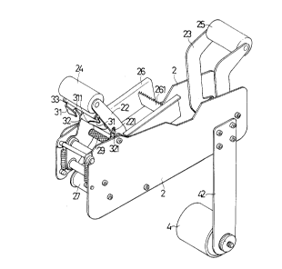
Please refer to Fig. 2. According to the first
preferred embodiment of the present invention, the band
2lgo&}3
attaching device has two locating boards 2, a front and a
rear band pressing wheel supports 22, 23 which are
movable relative to each other via a linking support 21
and urged by strong spring (not shown), a front and a
rear band pressing wheels 24, 25 disposed on the front
and rear band pressing wheel supports 22, 23, a band
cutting blade support 26, a band cutting blade 261
disposed thereon, a first band guiding wheel 27 through
which a band 41 upward passes and a band reel support 42
on which a band reel 4 is disposed. Two band stopper
boards 31 are disposed on the front band pressing wheel
support 22 under the front band pressing wheel 24. The
outer sides of the band stopper boards 31 are secured on
two lateral sides of the front band pressing wheel
support 22. The band stopper boards 31 respectively
extend from two lateral sides to the center and are
inclined toward the front side of the front band pressing
wheel 24. The free ends of the band stopper boards 31
define a clearance. A second band guiding wheel 29
embossed with checker on surface is disposed on the front
band pressing wheel support 22 under the band stopper
boards 31. A one-way rotatable band braking wheel 28 and
a third band guiding wheel 20 are disposed between the
locating boards 2 and between the band reel support 42
and the first band guiding wheel 27.
2190813
A fourth band guiding wheel 32 is disposed between
the band stopper boards 31 and the second band guiding
wheel 29. The fourth band guiding wheel 32 has a
predetermined weight and a shaft end 321 movable within a
shaft hole 221 of the front band pressing wheel support
22. In this embodiment, the shaft hole 221 is a
substantially vertical slot, whereby when the shaft end
321 is positioned at a relatively high position in the
slot 221, the front edge of the outer surface of the
fourth band guiding wheel 32 is tangent to the two band
stopper boards 31, while when the shaft end 321 is
positioned ata lowest position in the slot 221, the front
edge of the outer surface of the fourth band guiding
wheel 32 intersects the band stopper boards 31.
Please refer to Fig. 3. After the band 41 is pulled
out from the band reel support 42, the band 41 first
upward passes through the third band guiding wheel 20 on
the adhesive face 41A and then upward passed through the
first band guiding wheel 27 and the fourth band guiding
wheel 32 and the space between the band stopper boards 31
on the adhesive-free face 41B. Then the end of the band
41 is tangent to the front band pressing wheel 24 on the
adhesive-free face 41B.
2190813
Please refer to Fig. 4. During the case sealing
operation, the band 41 is attached to the front side of
the case 5 and pulled out and tensioned by the case 5. At
this time, the shaft end 321 of the fourth band guiding
wheel 32 is driven to move upward along the slot 221 to
the relatively high position. Furthermore, a section of
band 41 between the front edge of the outer surface 322
of the fourth band guiding wheel 32 and the front band
pressing wheel 24 is tangent to or not in contact with
the two band stopper boards 31 so as to facilitate
straight pulling out of the band 41.
Please refer to Fig. 5. When the case sealing
operation is completed, the band 41 is cut off and itself
upright stands. At this time, the band 41 is no more
tensioned and the shaft end 321 of the fourth band
guiding wheel 32 due to its own weight slides downward
along the slot 221 to the lowest position so that the
front edge of the outer surface 322 of the fourth band
guiding wheel 32 intersects the two band stopper boards
31. Simultaneously, the band 41 is such urged by the
fourth band guiding wheel 32 that a section of the band
41 from the second band guiding wheel 29 to the band
stopper boards 31 is forced and bent as shown in Fig. 6
2190813
and guided by the forward inclined extending band stopper
boards 31 to project forward into an arch state.
Therefore, the upright standing ability of the band 41 is
enhanced without falling down.
In conclusion, the present invention enables the band
to be straightly pulled out without bending so as to
avoid rough attaching of the band. Moreover, the present
invention has no spring so that abnormal pressing force
and failure of resilience are eliminated.
In addition, a fifth band guiding wheel 33 can be
disposed between the front band pressing wheel 24 and the
band stopper boards 31 and secured on the front band
pressing wheel support 22 so as to offset the clearance
between the front band pressing wheel 24 and the band
stopper boards 31 and prevent the end of the band 41 from
being blown into the clearance by wind.
Please refer to Figs. 7 and 8. They illustrate the
structure of the second preferred embodiment of the
present invention. In which, the outer surface 332 of the
fourth band guiding wheel 32 is a convex curved surface,
so that a slightly curved space is formed between the
convex curved surface and these two band stopper boards
2190813
31. Due to the shape and weight of the fourth band
guiding wheel, it will press on the adhesive-free face
41B of the band 41 so that the band 41 is urged to
forward project into an arch state.
It is to be understood that the above description and
drawings are only used for illustrating one embodiment of
the present invention, not intended to limit the scope
thereof. Any variation and derivation from the above
description and drawings should be included in the scope
of the present invention.