Note: Descriptions are shown in the official language in which they were submitted.
2~91003~
P/563-64
- 1 -
LUBRICATION OF A ROLL JACKET OF A PRESS ROLLER
BACKGROUND OF THE INVENTION
The invention relates to a press roller
typically for use in a paper making machine and
particularly to distribution of lubrication over the
support for a roll jacket of the press roller.
The press roller to which the invention is
directed has a stationary carrier or beam and has a
revolving roll jacket, which rotates around the carrier
and is supported on the carrier by at least one support
element which can be pressed against the inside
circumferential surface of the roll jacket. Movement of
the roll jacket over the support element is at least
partially hydrodynamically lubricated. The support
element has a support surface that faces toward the
inside circumferential surface of the roll jacket and
extends in the running direction of the roll jacket. The
support surface has several oil feed points, by which
fresh lubricating oil is supplied to the support surface
at the region between the support surface and the inside
circumferential surface of the roll jacket, where the
feed of fresh lubricating oil takes place at least
partially independently of a pressure space which is
located at the carrier and the support element and which
acts on the support element.
Such press rollers are used, in particular, in
press devices with a so called extended press zone
sometimes called an extended, or wide, or long nip press
zone. Such press devices can be used, for example, in
SPEC~175547
2191003
- 2 -
the press sections of paper making machines, but also may
be used in sizing and glazing mills.
In such a press roller, significant friction
can occur during operation, i.e. while the roll jacket is
rotating, in spite of the at least partial hydrodynamic
lubrication. The friction causes roll jacket wear and
must be compensated by greater drive output.
It has already been proposed to spray
additional oil onto the inside circumferential surface of
the roll jacket at the entry region of the press zone in
the circumferential direction, in order to reduce the
drive output. It has also already been proposed to
provide the support surface of the support element with a
slit which extends over the entire width of the press
zone, in the intake side edge region. Friction losses
can be reduced to a certain extent by these measures.
However, if any of the roll jacket, a felt band passed
through the press zone, the material web or similar
material that is to be pressed, or the counter-surface,
for example, defined by a counter-roller, includes any
irregularities in the form of thicker points or uneven
areas, the pressure will become so high at certain points
that the press zone is supplied only with a very small
amount of oil there, or with no oil at all. At the
points in question, oil may be stripped off at the slit.
A press roller of the type indicated above is
known from DE 40 40 392 A1. Several grooves are provided
in a pocket formed in the support surface of the support
element. The grooves extend essentially over the entire
width of the press zone. Lubricant channels open into
each of these grooves. In one exemplary embodiment,
three grooves are provided in the pocket, wherein two of
the grooves lie behind one another in the direction of
SPEC\175547
2191003
- 3 -
the roller axis. It is possible to provide hydrostatic
support of the roll jacket, i.e., the liquid under
pressure itself supports the roll jacket during start-up
of the press arrangement, and to have the roll jacket be
hydrodynamically supported, i.e., the rotation of the
jacket builds up the lubrication support for the jacket
at normal circumference velocity. But here again,
because of irregularities in the roll jacket, or in a
felt band passed through the press zone, or in the
counter-surface, particularly formed by a counter-roller,
or by the web-like rolled product, areas of greater
pressure will occur, at which the oil supply is reduced
or even interrupted.
An additional factor is that the lubricants
which produce the hydrodynamic support of the roll jacket
in a press roller with hydrodynamic lubrication of the
support element are strongly heated on the path from the
intake side to the exit side of the support element. The
degree of heating of the lubricant film is dependent,
among other things, on its pressure progression and, in
this connection, particularly on the gradient and the
maximum of this progression, as well as on the machine
speed. Increased heating reduces the viscosity of the
lubricant oil, thereby reducing its hydraulic support
capacity, or even causes break down of the oil in certain
cases. In addition, as the machine speed increases, it
becomes more difficult to sufficiently cool the hot oil
film after it has passed through the lubricant gap, or to
replace it. A particular problem is that lubricant oil
that is introduced at the intake is not entrained to a
sufficient degree and is not drawn into the lubricant
gap. This is again attributable, among other reasons, to
the uneven thickness of the elements which jointly pass
SPEC\175547
CA 02191003 2005-03-04
- 4 -
between the support element and the counter-roller, as
mentioned before.
Great differences in thickness of the elements
passing the support element also frequently result in
wedging between the support element and the counter-
roller, particularly in the recessed pocket, and thereby
cause destruction. Consider also that in a
hydrodynamically produced lubricant gap, the thickness of
the lubricant film is at its lowest value at the location
with the greatest negative ratio of the local pressure
gradient to the local viscosity, in terms of amount. In
normal press zones, this location is in the region of the
press zone exit, where a negative value results as the
pressure drops.
SUMMARY OF THE INVENTION
The present invention is directed towards the
provision of a press roller of the type described above,
in which an optimum supply of fresh, cool lubricant oil is
guaranteed even under varying operating conditions, to ensure
2o the most uniform possible temperature distribution over the
support surface of the support element.
According to the invention, the support surface
has at least one axially extending row of a plurality of
oil feed points that extends in the direction of the
roller axis. The feed points are separated from one
another. They are supplied at least partially
independently of the hydraulic pressure space which acts
on the support element in the direction toward the
counter-roller.
Each oil feed point comprises a bore in the
support surface extended into the support elements. In
the region of each bore, and preferably in its interior,
SPEC\ 175547
2191003
- 5 -
throttling occurs. This may be where the oil feed points
are preferably formed by a local depression of the
support surface and by a throttling bore opening into
this depression, and where separating ridges are provided
between the depressions, and the surfaces of the ridges
lie at least essentially on the same level as the rest of
the support surface.
This formation guarantees a uniform supply of
fresh, cool lubricant oil even if increased pressure is
cause at certain points over the support surface by
irregularities in the roll jacket, or in a felt band or
similar material passed through the press zone, or in the
material web to be treated, particularly paper or
cardboard, or in the counter surface, for example formed
by a counter roller. Such an uninterrupted supply of
fresh, cool lubricant oil is therefore particularly
guaranteed even at those locations where scraps of paper,
folds or thickened areas of the fiber web to be treated,
for example, pass through the press zone. While cross
flow or axial flow of the lubricant oil along the support
surface is practically precluded by the ridges, the bores
with their throttle characteristics ensure that excessive
lubricant oil will not escape due to a locally reduced
load, in other words, due to a gap opening, particularly
at a border region, and thus assures that the supply of
oil to those press locations under a greater load is not
lost. Because of this separation of the plurality of oil
feed points in an individual row; as well as of the feed
being at least partially independent of the pressure
space for the support element, sufficiently high pressure
is provided and any local irregularities which occur can
be compensated without difficulty. This practically
precludes the possibility that local irregularities which
SPEC\175547
~19i003
- 6 -
occur might temporarily or might permanently reduce or
interrupt the feed of fresh, cooled pressure oil. Oil
supply is guaranteed, particularly at the critical points
of high pressure stress. Therefore, another goal of
obtaining the most uniform possible temperature
distribution can also be achieved. The press roller
according to the invention can therefore advantageously
be used particularly also for those press devices in
which it is normally expected that paper scraps or folds
or thickened areas of fiber material will pass through
the press zone. The same set of problems also always
occurs at the edges of the product web, where the web
thickness abruptly ends.
The row of oil feed points in each instance
preferably has at least one distribution channel formed
in the support element assigned to it. That channel may
supply several oil feed points jointly with fresh
lubricant oil. Also, several distribution channels which
lie one after the other in the direction of the roller
axis can be provided. The bores can be individually
connected with a respective distribution channel, at
least in part, and/or can be brought together in groups
and connected with the distribution channel in these
groups, at least in part.
Preferably, means individually adjust the
pressure values and/or amount of fresh lubricant oil that
is supplied, with regard to individual bores and/or
groups of bores. This makes it possible to adapt the
press roller to different operating conditions, as
needed, in the simplest manner possible.
The oil supply to an individual row of oil feed
points can be accomplished completely independently of
the pressure space which acts on the support element or
SPEC\175547
2191003
partially via this pressure space. Combined lubrication
including oil delivered via the pressure space provides
the contact pressure for the support element and provides
additionally supplied oil, so that good emergency
lubrication may still be provided via the pressure space,
if the additional oil supply fails. This type of
lubrication can be used for all the support elements,
independent of the type of line force generation (e. g.,
long piston, piston row, pressure profile change,
pressure profile adjustment with flexible contact strip,
etc . ) .
It is advantageous if the supply of fresh
lubricant oil along a row of oil feed points alternates
between oil supply independently of the pressure space
which acts on the support element on the one hand and
supply via the pressure space which acts on the support
element on the other hand.
In addition to the at least one row of a
plurality of oil feed points, which are separated from
one another and are supplied at least partially
independently of the pressure space which acts on the
support element, there may be at least one more row of a
plurality of oil feed points, oriented parallel to the
first row, separated from one another, and supplied with
oil via the pressure space. In this case, a first row
with one type of supply and a second row with the other
type of supply, and parallel to the first row, can
alternately be provided in the running direction of the
roll jacket. Different rows of oil feed points which are
separated from one another and are supplied at least
partially independently of the pressure space are
preferably supplied with fresh lubricant oil separately
from one another.
SPEC\175547
~~- 2~9~003
_8_
It is possible to optimally adapt to different
operating conditions if the pressure values for the oil
feed points in one row which are supplied at least
partially independently of the pressure space, and/or the
pressure values for the oil feed points in different
rows, which are supplied at least partially independently
of the pressure space, can be adjusted separately. For
variable adjustment of different pressure progressions,
it is also possible to have support elements which can be
pushed against one another radially. In this case, it is
practical to seal adjacent support elements off relative
to one another, without a gap.
Particularly with regard to optimum temperature
distribution, it is advantageous to provide several
parallel rows, each having a plurality of oil feed
points, separated from one another, supplied at least
partially independently of the pressure space, where the
oil feed points of two adjacent rows are preferably
offset relative to one another crosswise to the running
direction of the roll jacket, i.e., the points in one row
are arranged in the axial direction gap relative to the
points in another, adjacent row.
Particularly with regard to the most uniform
possible temperature distribution which is a goal, it is
also advantageous if at least one row of a plurality of
oil feed points, separated from one another, and supplied
at least partially independently of the pressure space,
is arranged in the region between 1/4 to 3/4, and
preferably 1/2 to 3/4 of the support surface, as viewed
in the running direction of the roll jacket.
Other features and advantages of the present
invention will become apparent from the following
SPEC\175547
9 - 219 j 003
description of exemplary embodiments of the invention
which refers to the accompanying drawings.
BRIEF DESCRIPTION OF THE DRAWINGS
Figure 1 is a schematic view, partially in
cross-section, of a part of a press roller where it meets
a counter-roll and showing the invention,
Figure 2 is a top view of a part of the support
element of the press roller shown in Figure 1, with the
roll jacket omitted,
Figure 3 is a cross-section through part of the
support element shown in Figure 2, cut along the row of
oil feed points,
Figure 4 is a schematic cross-sectional view of
a press roller comparable to the one roller in Figure 1,
but where an oil feed point that is supplied via the
pressure space is shown,
Figure 5 is a schematic, perspective partial
view of a second support element embodiment provided with
two rows of oil feed points,
Figure 6 is a schematic view of an exemplary
embodiment of an oil feed point,
Figure 7 is a schematic view of another
exemplary embodiment of an oil feed point, and
Figure 8 is a view comparable to Figure 3,
showing the depressions at the oil feed points in detail.
DETAILED DESCRIPTION OF PREFERRED EMBODIMENTS
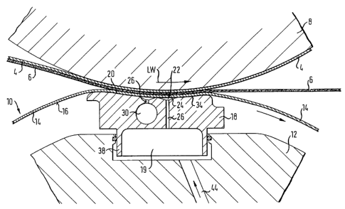
Figures 1 and 4 provide a schematic view of a
press roller 10 comprising a stationary carrier or beam
12 and a rotating roll jacket, 14. A typical roll jacket
is typically a plastic composition, endless loop,
flexible belt, which develops a generally rounded cross-
SPEC\175547
2191003
- 10 -
section due to centrifugal force and which also deforms
to the profile of the support surface of the support
element and the counter roll as the roll jacket moves
through the press nip at the press zone. The roll jacket
14 rotates around the stationary carrier 12. It is
supported on the carrier 12 by at least one support
element 18 which can be pressed against the inside
circumferential surface 16 of the jacket 14.
The support element 18 is often called a shoe
and the press roller may be called a shoe press roller.
The support element 18 includes a support surface 20
which faces the inside circumferential surface 16 of the
roll jacket 14. That surface is at least in part
hydrodynamically lubricated in the present case. The
support surface 20 is extended in the running direction,
LW of the roll jacket 14 over the surface 20, in order to
form a so-called extended press zone together with a
counter-surface, which is formed, for example, by a
counter-roller 8.
Additional fresh, cooled lubricant oil is
provided to the lubrication gap formed between the roll
jacket 14 and the support surface 20. For this purpose,
the support surface 20 has several oil feed points 22
(see also Figures 2, 3, and 5-9). Additional fresh
lubricant oil is provided at least partially
independently (meaning including up to completely
independently) of a pressure space 19 that is formed
under the support element and in the carrier 12, where
the pressure in the space 19 acts on the support element
18.
There may be a plurality of separately
pressable support elements arrayed along the axis of the
press roller.' It is advantageous if each one can be
SPEC\175547
2191003
- 11 -
moved in the radial direction relative to the others,
particularly in order to obtain different pressure
progressions. Basically, it is also possible to seal the
support elements 18 relative to one another without a
gap, at least in groups, while maintaining their desired
relative mobility.
The oil feed points 22 are arranged in axial
rows. At least one row R; extends in the direction of
the roller axis and is comprised of a plurality of oil
feed points, axially separated from one another, and each
supplied at least partially independently of the pressure
space 19 (Figures 2, 3, S, and 6). Each oil feed point
22 is preferably formed by a local depression 24 in the
support surface 20 and a capillary-like bore 26 from the
pressure space 19 which opens into the depression 24.
Ridges 28 are provided in the axial spaces between and
define the depressions 24. The ridges have outward
surfaces that preferably lie at least essentially on the
same level as the remainder of the support surface, i.e.,
they are not recessed.
In each of the embodiments shown in Figures 2
to 4, only one axial row of oil feed points 22 is
provided. In contrast, the embodiment variants shown in
Figures 1 and 5 contain two such rows. However, a
different number of rows, and particularly a greater
number of rows, may also be provided. In addition, it is
possible that rows of oil feed points extend only over
part of the axial width of the support element 18 and
also possible that adjacent rows are arranged in such a
way that one extends over one part of the axial width,
while the other extends over all other parts of the axial
width.
SPEC\175547
2191003
- 12 -
An oil distributor channel 30 is preferably
formed in the support element 18. One channel can be
provided for each of the rows R; of oil feed points 22
(see Figure 1). Each channel preferably extends
generally in the direction of the roller axis.
Several oil feed points 22 in one row are
jointly supplied with fresh, cool lubricant oil via each
distributor channel 30. In the simplest case, each row
R; of oil feed points can have a single distributor
channel 30 assigned to it. It is also possible, however,
to provide several distributor channels 30, which lie one
after the other in the direction of the roller axis, for
each row R;. Basically, oil feed from one axial side or
also from both axial sides of the support element is
possible. The oil distributor can be cylindrical or can
be conical along its length, for example, or can also
have a stepped cross-section. Finally, it is
advantageous if the cross-section of the inlet opening,
or the total of the cross-sections of the inlet openings
of the distributor channel 30, be greater than the total
of all the cross-sections of the bores 26 connected with
this channel.
In an embodiment which is preferred for
practical reasons, each bore 26 has a diameter in the
range of about 0.3 mm to 3 mm, and preferably 1 mm. The
length of each bore 26 is preferably about 5 to 100 mm,
and preferably 5 to 50 mm. Instead of forming the bores
as capillary-like, however, other types of throttling are
also possible, as a matter of principle.
In addition, it is necessary that the oil
pressure in the region of the inlet openings of the bores
26 be greater than the pressure in the lubricant film 34
over the support surface 20 of the support element 18.
SPEC\175547
'- .~ 2191003
- 13 -
The bores 26 can be connected individually with
the distributor channel 30, at least in part. According
to Figure 3, however, the bores 26 can also be grouped
together, at least in part, and can be connected with the
distributor channel 30 in groups. In the embodiment
shown in Figure 3, the bores 26 are grouped in pairs and
are connected with the distributor channel 30 via a feed
line 33 which is common to the pair of bores in question.
Other means, particularly valves, throttle
valves or similar means, may be provided in order to
separately adjust the values for pressure and/or for the
amount of the fresh lubricant oil to be supplied, with
regard to individual bores 26 and/or groups of bores 26.
In the embodiment of Figure 3, such a valve 36 is used in
each of the feed lines 33. Basically, however, it is
also possible to assign individual means of control and
regulation to at least individual bores 26. Each bore
may be provided with a respective shutter to shut off oil
flow therethrough, as well.
With regard to a row R; of oil feed points 22
in each instance, the supply of fresh, cooled lubricant
oil can take place completely independently of the
pressure space 19 which acts on the support element 18,
or also the supply can be partially via this pressure
space 19. Figure 4 shows an oil feed point 22 including
a bore 26 which opens directly into the pressure space 19
which acts on the support element 18. In contrast, in
the embodiment shown in Figure 3, the feed lines 33 are
connected with the distributor channel 30, which is
supplied with fresh, cooled lubricant oil from the
outside, i.e., independently of the pressure space 19
which acts on the support element 18.
SPEC\175547
2~9~00~
- 14 -
Instead of supplying all the oil feed points 22
of a row R; in each instance externally, it is also
possible, for example, to provide the supply of fresh
lubricant oil along the row R; alternately independently
of the pressure space 19 and via the pressure space 19.
Adjacent oil feed points 22 of a row, in each instance,
are then supplied in different ways.
Furthermore, in addition to at least one row R;
of a plurality of oil feed points, separated from one
another, and supplied at least partially independently of
the pressure space, there is at least another row of a
plurality of oil feed points parallel to the first row,
and again separated from one another, but supplied via
the pressure space. The rows R; are preferably arranged
so that they alternate, preferably one row R; of a
plurality of oil feed points 22, which are separated from
one another, are supplied at least partially independent
of the pressure space, and a parallel row R; of a
plurality of oil feed points 22, which are independent of
one another, are supplied via the pressure space.
Combined lubrication having an oil feed both
via the pressure space and from the outside has the
advantage, among others, that if the additional oil
supply fails, sufficient emergency lubrication will still
be ensured via the pressure space. This type of
lubrication can be used for all of the support elements,
independent of the type of line force generation, e.g.,
long piston, piston row, pressure profile change,
pressure profile adjustment with flexible contact strip.
With a plurality of rows R; each including a
plurality of oil feed points 22, separated from one
another, and supplied at least partially independently of
the pressure space, a separate supply of fresh lubricant
SPEC\175547
2191~~3
.,
- 15 -
oil can be provided to each or to all of the rows.
Preferably, the pressure values for the oil feed points
22 in one row R; which are supplied at least partially
independently of the pressure space, and/or.the pressure
values for the oil feed points, in different rows which
are supplied at least partially independent of the
pressure space, can be adjusted separately. It is also
possible to adjust the pressure values of several oil
feed points 22 jointly, as was described on the basis of
Figure 3.
The pressure adjustments can be done manually
or can also be electronically controlled. Preferably,
the oil pressure in the region of the inlet openings of
the bores 26 can also be adjusted to such a high value,
at least temporarily, that the roll jacket 14 is
hydrostatically supported, i.e., the liquid under
pressure itself supports the jacket. For practical
purposes, it is sufficient if such high pressure values
are generated during start-up. During operation,
lubrication should preferably be essentially
hydrodynamic, i.e., the rotation of the jacket builds up
the lubrication support for the jacket.
The depressions 24 define a continuous
transition into the support surface 20 partly formed by
the ridges 28, at least on one side of the oil feed
points in the surface 20. This transition is preferably
formed by a convex curvature. Such transitions can be
provided both in the running direction LW of the roll
jacket 14 (see Figures 1, 4, and 7 to 9), and in the
crosswise direction of the support element 18 (see Figure
3). This makes it possible for the depressions to make a
continuous transition into the support surface 20 partly
formed by the ridges 28, on all sides of the feed holes
SPEC\175547
2191003
- 16 -
22, for example. It is advantageous if each depression
24 has a maximum depth T of less than 0.5 mm,
particularly less than 0.3 mm, and preferably less than
0.1 mm.
According to Figure 2, the depressions 24 are
essentially circular, viewed from above. However, in a
top view, they can also have a rectangular, triangular or
diamond shape, or also a contour with straight or curved
or rounded edges. Further, the depressions 24 of one row
R;, can all have the same contour or respective different
contours in a top view, in such a way that adjacent
depressions 24 overlap when viewed in the running
direction LW, while a ridge 28 between them is
maintained.
In the embodiment shown in Figures 2 and 6, the
bores 26 of the oil feed points 22 are arranged upstream
or in front of the center of gravity of the support
surface depressions 24 in the support surface in the
running direction LW of the roll jacket 14, as seen in a
top view. This arrangement produces optimum oil
distribution in the depressions 24 during operation.
However, it is also possible to arrange all of the bores
26 directly at the center of gravity of the depressions
in a top view (Fig. '8) .
The embodiment shown in Figure 5 has several,
here two, parallel rows R;, each comprised of a plurality
of oil feed points 22 that are separated from one another
and are supplied at least partially independently of the
pressure space. Here, the oil feed points 22 of the two
adjacent rows R1 and R2 are offset relative to one another
by an amount A/2, crosswise to the running direction LW
of the roll jacket 14. This distance A/2 corresponds to
half the distance A between the bores in each row of oil
SPEC\175547
2i9i0Q3
- 17 -
feed points, where this distance is preferably
essentially the same in the two rows. In the two rows RI
and R2, therefore, the oil feed points 22 in each row are
arranged in the gap relative to the feed points in the
other row.
In a preferred embodiment, the bores 26 of the
oil feed points 22 of one row R; are spaced a distance A
of about 5 to 50 mm, particularly 10 to 30 mm, and
preferably about 20 mm apart from one another. In
addition, a distance of about 5 to 50 mm, particularly 10
to 30 mm, and preferably about 20 mm, for example, is
provided between the bores 26 of the oil feed points 22
of two adjacent rows R;, in the running direction LW of
the roll jacket 14.
For achieving the most uniform possible
temperature distribution over the support surface 20, it
is particularly advantageous if at least one row R; of a
plurality of separated oil feed points 22, which are
supplied at least partially independently of the pressure
space 19, is arranged in the region between 1/4 to 3/4,
and preferably 1/2 to 3/4 across the support surface,
viewed in the running direction LW of the roll jacket 14.
As shown in Figure 2, it is practical if the
width B of the ridges 28 is less than the diameter D of
the bores 26. For practical purposes, the width B of the
ridges 28 can be narrower than 10 mm, for example,
particularly narrower than 5 mm, preferably narrower than
1 mm and especially preferably narrower than 0.2 mm.
The depressions 24 provided in the support
surface 20 and the ridges 28 located between them are
preferably formed by etching, particularly by
electroerosion.
SPEC\175547
2191003
- 18 -
The embodiments of Figures 6 and 7 have the
common feature that the depression 24 of the oil feed
point 22, in each instance, makes a continuous transition
into the support surface 20 of the support element 18,
over an extended distance, in the running direction LW of
the roll jacket 14. In Figure 7, the support surface is
formed by ridges 28, which separate each oil feed point
22 from the next one.
Figure 8 shows a row of oil feed points with a
view in the running direction LW. The depression 24 of
each bore 26 is separated by a ridge 28 at the level of
the support surface 20. As is evident from Figure 8; the
ridge width B is less than the diameter of the bores 26.
The oil supply can be provided from at least
one lateral end surface, or by means of the support
element, or from the direction of the carrier, or via a
special oil feed pipe 44 (see Figure 1). Preferably,
each oil feed is pressure regulated. The oil flow
through the bores is regulated by the pressure drop which
occurs at each bore. The pressure oil can also be
supplied via the pressure piston 38, in part (see Figure
4~ .
The pressure drop across the capillary-like
bores results from their bore diameter, the bore length
and the consistency and the quantity of the oil. The
separation of the oil feed points of each individual row,
achieved by means of the ridges and the capillary-like
formation of the bores ensures that even when there are
non-uniform, different pressures, all regions will be
adequately supplied and the maximum flow of oil through
the bores will be limited. An optimum oil supply to
produce and maintain the lubricant film 34 (see Figure 1)
is therefore always guaranteed, even under critical
SPBC~175547
2191003
- 19 -
operating conditions such as when clumps or thickened
areas of paper pass through the press zone, for example.
In addition, an effective exchange of the oil adhering to
the roll jacket is always ensured. This results in
optimum temperature distribution with a low level of
warming of the lubricant film. This means that the
thermal stress on the roll jacket is also kept low. In
addition, the low level of warming of the lubricant film
reduces the risk of thermal deformation of the support
element. Even if irregularities occur, uniform
lubrication conditions can be achieved over the width of
the support element. In contrast, with purely
hydrodynamic or purely hydrostatic lubrication, there is
also greater freedom in structuring the pressure profile.
The elimination of depressions with edges, in the region
of the press zone, is also advantageous.
Although the present invention has been
described in relation to particular embodiments thereof,
many other variations and modifications and other uses
will become apparent to those skilled in the art. It is
preferred, therefore, that the present invention be
limited not by the specific disclosure herein, but only
by the appended claims.
SPEC\175547