Note: Descriptions are shown in the official language in which they were submitted.
CA 02191327 2003-10-21
-1-
LIQUID SPRING VE»CULAR SUSPENSION SYSTEM
AND ASSOCIATED CONTROL APPARATUS
BACKGROUND OF TAE INVIENTION
1fie present invention relates generally to vehicular suspension systems and,
in a
preferred embodiment thereof, more particularly provides a liquid spring
vehicular
suspension system in which the spring and damping characteristics of each
liquid spring are
S computer adjusted, during vehicle operation, in response to sensed
variations in liquid spring
and vehicle operating parameters.
In the past, various proposals have been made for replacing the conventional
hydraulic
shock absorber and exterior coil spring assemblies in vehicular suspension
systems with more
compact devices la~own as liquid springs. A liquid spring basically comprises
a cylindrical
housing having an internal chamber with a compressible liquid therein, a
piston reciprocably
disposed in the chamber, and a rod structure axially movable into and out of
the chamber,
secured to the piston, and having an outer longitudinal portion projecting
outwardly of one
of the housing ends. With the liquid spring operatively interconnected between
the vehicle
frame and an associated wheel support structure, the compressible liquid
within the liquid
spring generates both spring and damping forces in the suspension system in
response to
relative axial translation between the rod structure and housing of the liquid
spring caused
by relative vertical displacement between the wheel and the frame. A more
detailed
description of the general structure and operation of a liquid spring
incorporated in a
vehicular suspension system may be found in U.S. Patent No. 4,741,516 entitled
CA 02191327 2003-10-21
-2-
"FLUID SUSPENSION SPRING AND DAMPER FOR VEHICLE SUSPENSION
SYSTEM" .
Various mechanisms have been proposed for selectively adjusting the spring
force
and/or damping force characteristics of liquid springs to settings which
remain essentially
S constant during vehicle operation until readjusted when the vehicle is at
rest. Thus, these
essentially fvced spring force and damping force characteristics represent at
best
predetermined compromise settings adapted to handle an often wide uange of
road conditions
and vehicle operational inputs (such as steering input, bralang forces,
vehicle speed and the
like) encountered during operation of the vehicle.
It can be seen that it would be desirable to provide a liquid spring vehicular
suspension system in which the spring force and damping force characteristics
of the liquid
springs are automatically adjusted, during vehicle operation, to compensate
for variations in
both road conditions and vehicle operational inputs, or any combination
thereof. It is
accordingly an object of the present invention to provide such a system.
SLfMMA.RY OF 'THE I1VVF2ITTON
In carrying out principles of the present invention, in accordance with a
preferred
embodiment thereof, an improved liquid spring vehicular suspension system is
provided in
which the spring and damping force characteristics of each liquid spring are
continuously
computer adjusted, during vehicle operation, in response to sensed variations
in either or both
liquid spring and vehicle operating parameters.
Each liquid spring comprises a housing having a cylindrical chamber therein in
which
a piston is reciprocably disposed and axially divides the chamber into bounce
and rebound
subchambers. Coaxially secured to the piston, and slidahly and sealingly
carried by the
CA 02191327 2003-10-21
-3-
housing for axial movement relative thereto into and out of the chamber, is an
elongated,
hollow rod structure having an outer longitudinal portion projecting outwardly
of the housing.
A suitable compressible liquid is disposed within the bounce and rebound
chambers and
within the interior of the rod structure. A damping bypass passage, which
intercommunicates
the bounce and rebound chambers within the housing, is defined by the interior
rod chamber,
a first pair of fluid transfer pore formed tadially through the rod structure
closely adjacent
the rebound chamber side of the piswn, and a second pair of radially extending
fluid transfer
ports forms through the rod structure closely adjacent the bounce chamber side
of the piston.
First and second rotary valve means are disposed within the rod chamber and
are selectively
and independently operable to respectively meter compressible liquid flow
through the first
and second rod port pairs.
Each of the liquid springs has its longitudinally outer rod stzucture portion
secured
to the vehicle frame, and has its cylinder secured to an associated wheel
structure in a
manner such that vertical deflection of the wheel structure relative to the
frame causes
relative axial displacement between the rod structure and the housing and
causes the
compressible liquid to exert spring and damping forces that yieldingly and
reactively resist
vertical wheel displacement. First, second, and third control means are
provided and are
respectively operable to selectively and independently operative the first and
second valve
means to meter compressible liquid flow through the first and second rod port
pairs, to
selectively vary the effective volume of the compressible liquid, and to
selectively vary the
pressure of the compressible liquid.
Means are provided for generating liquid spring operating parameter signals
including
a first signal indicative of the relative axial position of the piston within
the housing chamber,
a second signal indicative of the compressible liquid pressure in the rebound
subchamber, a
CA 02191327 2003-10-21
-4-
third signal indicative of the compressible liquid pressure in the bounce
subchamber, and a fourth signal indicative of the compressible liquid pressure
in
the rod structure chamber. Additionally, means are provided for generating
vehicle
operating parameter signals which representatively include signals indicative
of the
road contour ahead of the moving vehicle, the sense and magnitude of steering
input to the vehicle, the speed of the vehicle, and the braking force being
exerted
on the vehicle.
Computer means receive the liquid spring operating parameter signals, and
the vehicle operating parameter signals, and responsively generate output
signals
that are used to operate the first, second and third control means in a manner
automatically adjusting the spring and damping characteristics of each liquid
spring
during vehicle operation.
In one aspect, the present invention resides in a suspension system for use
on a vehicle having a frame, a wheel structure, and an operating parameter,
said
suspension system comprising: liquid spring means, operably interposed between
said frame and said wheel structure for utilizing a compressible liquid to
exert
spring and damping forces to reactively control relative vertical displacement
between said frame and said wheel structure, said liquid spring means having
spring and damping characteristics, and an operating parameter, and means for
varying one of said spring and damping characteristics in response to a sensed
variation in at least one of said operating parameters. In a further aspect,
the
present invention resides in a suspension system for use on a vehicle wherein
the
means for varying one of said spring and damping characteristics include:
control
means selectively operable to vary said spring and damping characteristics,
means
for generating at least one liquid spring operating parameter signal, means
for
generating at least one vehicle operating parameter signal, and computer means
for
receiving said liquid spring and vehicle operating parameter signals and
responsively adjusting said spring and damping characteristics by operating
said
control means.
CA 02191327 2003-10-21
-4a-
In yet a further aspect, the present invention resides in a suspension system
for use on a vehicle having a frame, a wheel structure, and a means for
producing a
signal representative of a vehicle operating parameter, said suspension system
comprising: liquid spring means, operably interposed between said frame and
said
wheel structure, said liquid spring means including: a housing having a
chamber in
which a first volume of compressible liquid is disposed; piston means
reciprocally
disposed within said chamber and dividing it into bounce and rebound
subchambers; rod means carried by said housing for movement relative thereto
into
and out of said chamber and secured to said piston means; a second volume of
compressible liquid; and valve means selectively operable to place said second
volume in communication with said bounce subchamber and said rebound
subchamber through respective first and second port means disposed on opposite
sides of said piston means; said liquid spring means operable for utilizing
said
compressible liquid to exert spring and damping forces to both statically and
reactively control relative vertical displacement between said frame and said
wheel
structure, said liquid spring means having spring characteristics dependent
upon
liquid volume and pressure and damping characteristics dependent upon rate of
flow of liquid bypassing said piston; and control means for varying at least
one of
said volume, pressure or rate of liquid flow to change at least one of said
spring
and damping characteristics in response to a sensed variation in at least one
of said
signals representative of the operating parameters during operation of the
vehicle.
In a further aspect, the present invention resides in a suspension system for
use on a vehicle having a frame, a wheel structure, and a means for producing
a
signal representative of a vehicle operating parameter, said suspension system
comprising: (a) liquid spring means, operably interposed between said frame
and
said wheel structure, said liquid spring means including: (i) a housing having
a
chamber in which a first volume of compressible liquid is disposed; (ii) a
second
volume of compressible liquid; and (iii) means selectively operable to place
said
second volume in communication with said first volume; said liquid spring
means
operable for utilizing said compressible liquid to exert spring and damping
forces
CA 02191327 2003-10-21
-4b-
to both statically and reactively control relative vertical displacement
between said
frame and said wheel structure, said liquid spring means having spring
characteristics dependent upon liquid volume and pressure and damping
characteristics; and (b) control means for varying said at least one of spring
or
damping forces in response to a sensed variation in at least one of said
signals
representative of the operating parameters during operation of the vehicle.
In yet a further aspect, the present invention resides in a suspension system
( 10) for use on a vehicle having a frame ( 14), a wheel structure, and a
means for
producing a signal representative of a vehicle operating parameter, said
suspension
system (10) comprising: liquid spring means (12), operably interposed between
said frame ( 14) and said wheel structure, said liquid spring means ( 12)
including a
housing (18) having a chamber (36) in which a first volume of compressible
liquid
is disposed; piston means (40) reciprocally disposed within said chamber (36)
and
dividing it into bounce and rebound subchambers (36a,36b); rod means (46)
carried
by said housing (18) for movement relative thereto into and out of said
chamber
(36) and secured to said piston means (40); a second volume (52) of
compressible
liquid; characterized by valve means selectively operable and directly
responsive to
a control signal to place said second volume (52) in communication with said
bounce subchamber (36a) and said rebound subchamber (36b) through respective
first and second port means (70,72) disposed on opposite sides of said piston
means
(40); said liquid spring means (12) operable for utilizing said compressible
liquid
to exert spring and damping forces to both statically and reactively control
relative
vertical displacement between said frame (14) and said wheel structure, said
liquid
spring means (12) having spring characteristics dependent upon liquid volume
and
pressure and damping characteristics dependent upon rate of flow of liquid by
passing said piston (40); and control means (16) for varying at least one of
said
volume, pressure or rate of liquid flow to change at least one of said spring
and
damping characteristics in response to a sensed variation in at least one of
said
signals representative of the operating parameters during operation of the
vehicle.
CA 02191327 2003-10-21
-4c-
In a further aspect, the present invention resides in a suspension system
( 10) for use on a vehicle having a frame, a wheel structure, and a means for
producing a signal representative of a vehicle operating parameter, said
suspension
system comprising: (a) liquid spring means ( 12) operably interposed between
said
frame and said wheel structure, said liquid spring means including (i) a
housing
(18) having a chamber 36 in which a first volume of compressible liquid is
disposed; (ii) a second volume of compressible liquid in communication with
said
chamber (36); and (iii) spring rate adjustment means (96) operable on the
second
volume of compressible liquid to selectively increase or decrease the
effective
volume of compressible liquid in the liquid spring means ( 12); said liquid
spring
means ( 12) operable for utilizing said compressible liquid to exert spring
and
damping forces to both statically and reactively control relative vertical
displacement between said frame and said wheel structure, said liquid spring
means
(12) having spring characteristics dependent upon liquid volume and pressure
and
damping characteristics; and (b) control means (16) for varying said at least
one of
spring or damping forces in response to a sensed variation in at least one of
said
signals representative of the operating parameters during operation of the
vehicle,
wherein spring forces are varied through spring rate adjustment achieved by a
controlled change in the effective volume of compressible liquid in the liquid
spring means ( 12) using spring rate adjustment means (96).
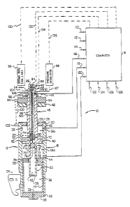
BRIEF DESCRIPTION OF THE DRAWINGS
FIGURE 1 is a schematic, partially cross-sectional illustration of a portion
of a computer-controlled liquid spring vehicular suspension system which
embodies principles of the present invention; and
FIGURE 2 is an enlarged scale cross-sectional view through the liquid
spring portion of the system, taken along line 2-2 of Fig. 1.
CA 02191327 2003-10-21
-4d-
DETAILED DESCRIPTION OF THE PREFERRED EMBODIMENTS
Schematically illustrated in Fig. 1 is a portion of an improved liquid spring
vehicular suspension 10 which embodies principles of the present invention and
representatively incorporates a generally vertically oriented, double rod end
type
liquid spring 12 at each wheel of the vehicle. In a manner subsequently
described, the liquid spring 12 is operatively connected at its upper end to
the
vehicle frame 14, and at its lower end to the support
W095/33142 , r y i i ; PCT/US94/06088
-5-
structure (not shown) of its associated wheel, and operates to provide the
requisite suspension
system spring and damping forces at its associated wheel location. Also as
latE;r described,
the liquid spring 12 is controlled in a unique fashion utilizing a computer 16
which
continuously and automatically adjusts key operational aspects of the spring
in response to
sensed variations in selected vehicle and liquid spring operating parameters.
Liquid spring 12 includes an elongated, generally vertically oriented tubular
housing
18 having an upper end 20 and lower end 22. A suitable mounting bracket 24 :is
secured to
the lower housing end 22 and is connected to the wheel support structure (not
shown). An
upper annular gland member 26 is threaded into the upper housing end 20, and
annular
intermediate gland member 28 is positioned within a vertically intermediate
pardon of the
housing interior, and a cylindrical plug member 30 is threaded into the lower
housing end
22 and is provided with a small central vent passage 32 extending axially
therethrough.
Extending axially within the housing interior between the gland 28 and the
plug 30 is an
elongated cylindrical spacer sleeve 34.
The gland members 26, 28 and the plug 30 define within the housing interior an
upper
chamber 36, which contains a compressible liquid, and a vented lower rod
travel chamber
38. An annular piston 40 is vertically reciprocably within the upper chamber
36 and divides
it into an upper "rebound~ chamber 36a, and a lower "bounce" chamber 36b. For
purposes
later described, a pair of small side wall ports 42 and 44 are formed in the
housing 18 and
respectively extend into the chambers 36a, 36b adjacent the upper and lower
gland members
26, 28. An elongated hollow cylindrical rod structure 46 is coaxially secured
to the annular
piston 40 and includes an upper rod section 48 extending upwardly from the
upper end face
of piston 40, and a smaller diameter lower rod section 50 extending downwardly
from the
lower end face of the piston. Rod structure 46 has a cylindrical, compressible
liquid-filled
W095/33142 .~, .. i : t PCT/U994/06088
-6-
interior chamber 52 extending between its closed upper and lower ends 54 and
56 and
passing through the central opening in piston 40.
The upper rod section 48 is slidably and sealingly carried within a suitable
seal
stricture 58 in upper gland member 26, and the lower rod section 50 is
similarly carried
within a seal structure 60 within the intermediate gland member 28. An upper
end portion
of rod section 48 is extended upwardly through a resilient bounce pad member
62, a rigid
bounce retainer member 64, and the vehicle frame 14. Such upper rod end
portion is
captively secured to the frame 14 by means of a lock nut 66 threaded onto the
upper rod end
and bearing against the frame 14.
With the vehicle at rest, the portion of its weight borne by the wheel
structure
associated with the illustrated liquid spring 12 exerts a downward axial force
on the upper
rod s~tion 48 tending to force it further into the chamber 36 while at the
same time forcing
the smaller diameter rod section 50 downwardly through the intermediate gland
member 28
and into the vealted chamber 38 to simultaneously withdraw the lower rod
section 50 from
1S the chamber 36. Downward rod structure movement in this manner
progressively decreases
the volume of the compressible liquid within the chamber 36 due to the
difference in the
outer diameters of the upper and lower rod sections 48, 50. This volume
decrease, in turn,
' increases the pressure of the compressible fluid which exerts a
progressively increasing net
upward force on the piston and rod structure due to the fact that the diameter
of the lower
seal 60 is less than the diameter of the upper seal 58. When this net,
upwardly directed fluid
pressure farce on the piston and rod structure equals the portion of the
vehicle weight borne
by its associated wheel structure, the piston 40 is at a vertical equilibrium
point within the ,
housing chamber 36 - a point which, as a general proposition, establishes the
"ride height"
of the vehicle when it is at rest or travelling along essentially level
terrain.
WO 95133142 ~ ~, ' 219 i 3 2 7 PCT~S94106088
~:. .. ! \ c .1
_7_
When an additional, upwardly directed "bounce" force is imposed upon the wheel
structure, the housing 18 is moved further upwardly along the rod structure 46
ini a manner
further inserting the larger diameter rod section 48 into the chamber 36 while
at the same
time further withdrawing the smaller diameter rod section 50 therefrom and
progressively
S increasing the compressible liquid pressure and the net upward pressure
force on the piston
40. When the upward wheel structure force is decreased, for example when the
wheel
structure travels downwardly through the "rebound" portion of its overall
wheel !stroke, the
internal fluid pressure force within the housing 18 acts to drive the housing
downwardly
relafive to the rod structure 46. In this manner, the rod travel-responsive
pressure variations
in the compressible fluid provide the liquid spring 12 with the "spring"
portion of its overall
suspension action.
The "damping" portion of the spring's overall suspension action is
accomplished in
the present invention by controllably permitting compressible liquid bypass
flow across piston
40 from bounce chamber 36b, through rod chamber 52 and into rebound chamber
36a as the
1S housing 18 is deflected upwardly relative to the piston 40, and
controllably permitting
compressible liquid bypass flow across the piston from rebound chamber 36a,
tturough rod
chamber 52 and into bounce chamber 36b as the housing 18 is deflected
downwardly relative
to the piston 40. Such damping bypass flow is representatively provided for by
means of a
diametrically opposed pair of radially extending ports 70 formed through upper
lod section
48 just above the piston 40, and a diametrically opposed pair of radially
extending ports 72
formed through lower rod section 50 just below the piston 40.
Inward and outward flow through the rod ports 70, 72 may be selectively
controlled
by a pair of cylindrical rotary valve members 74, 76 coaxially and stidably
disposed within
the interior of rod structure 46, and respectively covering the inner ends of
rod ports 70 and
WO 95/33142 :, ~, ,, ~ r~~ 219 i 3 2 7 P~~S94106088
-8-
rod ports 72. Lower valve member 76 has axially formed therethrough a
diametrically
opposed pair of peripherally disposed metering passages 78 (see Fig. 2} having
generally
teardrop shaped cross-sections. By rotating the valve member 76 relafive to
the rod structure
46, the valve member passages 78 may be moved into and out of metering
registration with
the rod ports 72 to thereby meter compressible liquid flow between bounce
chamber 36b and
rod chamber 52. In a similar fashion, the upper rotary valve member 74 is
provided with
axially extending peripheral metering of passages 80 which, upon appropriate
rotation of the
valve member 74, may be moved into and out of metering registration with the
rod ports 70
to thereby selectively meter compressible liquid flow between the bounce
chamber 36a and
the rod chamber 52.
The lower valve member 76 is secured to and may be rotated by an elongated
actuating shaft 82 which extends upwardly through the rod chamber 52 and
outwardly
through the upper rod end 54. The upper end of shaft 82 is operatively secured
to a high
speed rotary actuator 84 disposed within a small control housing 86 secured to
the upper end
of a similar control housing 88 affixed to the upper rod end 54. A hollow
tubular control
rod 90 slidably circumscribes the rod 82 and is secured at its lower end to
the valve member
74 which also slidably circumscribes the rod 82. The upper end of the outer
rod 90 is
operatively secured to a high speed rotary actuator 92 disposed within housing
88. It can be
seen that by appropriately operating the rotary actuators 84 and 92 the rods
82 and 90, and
thus the valve members 76 and 74, may be selectively and independenLty rotated
within the
rod structure 46 to accordingly selectively and independently meter to a
desired degree
compressible liquid flow in either radial direction through the rod ports 70
and 72. if ,
desired, the actuators 84 and 92 could be disposed with the interior of upper
rod section 48.
W095I33142 ; ~ ~ s PCT/US94I06088
'~ ,y ''. I \ ~ ._,
-9-
The use of the valves 74, 76 in conjunction with the compressible liquid-
filled rod
chamber 52 and the rod ports 70, 72 permits both the bounce and rebound
damping
characteristics of the liquid spring 12 to be selectively, independently and
quite rapidly varied
(by rotation of either or both of the valve control rods 82, 90) within a very
wide adjustment
range. For example, with both of the valves 74, 76 rotated to their maximum
open positions
relative to rod ports 70 and 72, the damping forces on piston 40 as the hou
sing 18 is
deflected in either vertical direction are at their minimum magnitudes - the
piston bypass
passage defined by rod ports 70 and 72, the valve passages 78 and 80, and the
rai chamber
52 being at its least restrictive setting. At the other end of the damping
spectNm, 'when both
of the valves 74, 76 are rotated to close off their associated rod ports 70
and 78, the
available bounce and rebound damping forces are maximized.
Between these two extremes lie a nearly infinite number of relative valvE;
positions
and correspondingly available bounce and rebound damping force settings. Not
only may
the aforementioned piston bypass passage be variably restricted by valves 74
and '76, but the
rod chamber 52 may also be selectively communicated with or shut off fmm
either or both
of the rebound and bounce chambers 36a and 36b, thereby nearly instantaneously
adding or
subtracting the rod chamber compressible liquid volume to or from either or
both of the
bounce and rebound chambers to further modify the damping characteristics of
the liquid
spring 12. This permits the rod chamber compressible liquid to be used, for
example, to
store compression energy as the housing 18 is deflected in one vertical
direction, and release
the stored compression energy as the housing deflects in the opposite vertical
du~ection.
Further control elements operatively associated with the liquid spring 12
include a
photoelectric position sensor 94, a spring rate adjustment mechanism 96, and a
pressure
regulator mechanism 98, each of which is schematically depicted in Fig. 1.
Position sensor
W095/33142 "' J ~ j .; PCTIUS94106088
-1o-
94 is secured to the bounce retainer member 64 and is operative to project a
light beam 100
onto a position indicating tab 102 movably carried by the upper end of the
housing 18. The
beam 100 is reflectively returned from the tab 102 to the sensor 94, thereby
permitting the
sensor 94 to instantaneously sense the vertical distance therefrom of the tab
102. Such
distance is, of course, directly correlated to the distance between the upper
end of the
housing 18 and the bounce pad 62, and to the position of the piston 40
relative to the
opposite ends of the compressible liquid-filled chamber 36. It will be
appreciated that the
sensor 94 and its associated tab 102 could be mounted on a variety of
alternate, relatively
movable portions of the rod and housing sections of the liquid spring if
desired.
The spring rate adjustment mechanism 96 is provided with an interior,
compressible
liquid-filled chamber (not shown) which is selectively compressible and
expandable and is
communicated with the rod chamber 52 via a conduit 104 connected to a side
wall transfer
port 106 formed radially through the upper end of the rod section 48. By
expanding the
inbesnal chamber in the mechanism 96, the effective overall compressible
liquid volume of
the liquid spring 12 is increased, while contracting such chamber decreases
the effective
compressible liquid volume.
The pressure regulator mechanism 98 may be of a construction similar to that
of
spring rate adjustment mechanism 96, having an internal, compressible liquid-
felled chamber
which is selectively compressible and extendable, and communicates with the
rod chamber
52 via a conduit 107 and a rod side wall port 108. By selectively compressing
or expanding
' the internal chamber of mechanism 98, the pressure of the compressible fluid
within the
liquid spring housing and rod chambers 36 and 52 may be selectively varied.
To uniquely control the operation of the liquid spring 12 during vehicle
operation,
control input signets 110, 112, 114, 116, 118 and 120, each associated with an
operational
PC1'/US941'06088
W095133142 _;:_ Z 19~:~ 327
-11-
aspect of the liquid spring itself, are transmitted from the liquid spring 12
to the computer
- 16. Input signal 110, suitably transmitted from the position sensor 94, is
indicative, as
previously described, of the distance between the upper end of the housing 18
and the
resilient bounce pad 62, and is therefore indicative of the axial position of
the piston 40
relative to the opposite ends of the chamber 36 defined by the gland members
26 and 28.
Input signals 112 and 114 are respectively indicative of the rotational
positions of the upper
and lower valve member 74 and 76 relative to their associated rod ports 70 and
72. Input
signals 116, 118 and 120 are pressure signals transmitted to the computer via
suitable
conduits connected to a rod port 121, and the previously mentioned housing
ports 42 and 44,
and are respectively indicative of the compressible liquid pressures in the
rod chamber 52,
the rebound subchamber 36a, and the bounce subchamber 36b.
In addition to the input signals 110-120 representing selected operational
parameters
of the liquid spring itself, input signals 122, 124, 126 and 128, each
indicative of a
representative operational parameter of the vehicle, are suitably transmitxad
to thE; computer
16. Signal 122 is indicative of the road contour ahead of the vehicle, signal
124 is'. indicative
of the degr~ and sense of the steering input to the vehicle, signal 126 is
indicative of the
vehicle's speed, and signal 128 is indicative of the braking force being
exerted upon the
vehicle.
Output signal 130 is used to operate the spring rate adjustment mechanism 96
to
selectively increase or decrease the effective volume of compressible liquid
in the liquid
spring structure, output signals 132 and 134 are used to respectively operate
the high speed
rotary actuators 84 and 92 used to rotate the damping valves 74 and 76, and
ouatput signal
136 is used to operate the pressure regulator mechanism 98 to selectively vary
the
compressible liquid pressure within the liquid spring.
WO 95/33142 1 =, .~v ;~ ~'g.:.~ 3 2 7 PCTIUS94106088
-12-
In this manner, both the spring force characteristics and the bounce and
rebound
damping characteristics of liquid spring 12 (and, or course, the liquid
springs operatively
associated with the other vehicle wheels) are continuously monitored and
automatically varied
in response to variations in both vehicle operating parameters and positional
and pressure
operating parameters of the liquid spring itself. For example, the previously
described
continuous sensing of the liquid pressures in rebound and bounce subchambers
36a and 36b,
and the vertical position within housing chamber 36 of piston 40, enables
computer 16 to
compute, at any given instant, the direction of relative taavel of the piston,
its velocity, and
its acceleration relative to the housing, and responsively vary one or more of
the output
signals 130-136 to substantially instantaneously adjust the effective piston
velocity andlor
acceleration during either a bounce or rebound stroke of the wheel structure.
It can thus be seen that the control system schemarically depicted in Fig. 1
may be
conveniently utilized to continuously and automatically adjust the spring and
damping
characteristics of the liquid spring 12 to generally optimize its suspension
performance
is essentially regardless of what combination of road conditions and driver
control inputs the
operated vehicle encounters at a given instant.
It should be noted that the schematically illustrated suspension system 10 is
merely
. representative and could be modified in a variety of manners if desired. For
example, the
liquid spring 12, while illustrated as a double rod atd type, could alto be of
the single rod
end type, and could be interconnected between the vehicle frame and wheel
structures in a
variety of alternate manners and orientations. The sensing of the housing and
piston
positions could be achieved in a variety of alternate manners, as could the
variable damping
bypass flow across the piston 40. Further, the volume and pressure adjustment
mechanisms
96, 98 could be structured and controlled differently, and the number and type
of liquid
WO 95133142
PC1'IUS94,~06088
3! ~~ f~,191327
-13-
spring and vehicle operating parameter input signals could be varied to suit a
particular
- suspension application.
The foregoing detailed description is to be clearly understood as being given
by way
of illustration and example only, the spirit and scope of the present
invention being limited
solely by the appended claims.