Note: Descriptions are shown in the official language in which they were submitted.
2191~65
MPM/ph/12104
The present invention relates to a device for the
separation and classification of particles forming a granular
product, this device comprising a vessel for separation of
particles, means for supplying particles to the vessel, a
separation means for these particles formed of at least one
movement generator arranged to generate in said separation
vessel a longitudinal flow of a fluid entraining said parti-
cles, and means for recovery of said particles.
It also relates to a process for the separation and
classification of particles forming a granular product, in
which said particles are progressively introduced into a
separation device as defined above, and the particles are
collected on at least one recovery means disposed below said
vessel, having account for their longitudinal position on
these recovery means.
There exist at present several processes permitting
the separation of particles constituting a granular product
such as a powder, pellets or grains.
Among these processes can be cited the separation by
screening which consists in disposing the product on a series
of superposed screens having progressively finer mesh, and
recovering the product on each screen.
2191~6S
This process has various drawbacks due particularly
to clogging of the screen and erosion of the particles against
the mesh of the screen.
Another process permitting the separation and
classification of particles of a granular product, as well as
the device for practicing it, are described in U.S. patent No.
4,213,852. The device comprises a closed vessel in which is
disposed a tube having one upstream end and one downstream
end. A hopper is disposed above this tube adjacent its
upstream end and permits introducing the particles. A fan is
mounted adjacent the downstream opening of the tube and
generates an air flow in a closed circuit, circulating in one
direction in the tube and in the other direction between the
tube and the closed vessel. Wire are disposed adjacent the
upstream end of the tube so as to decrease turbulence in the
air flow and thereby to create as laminar a flow as possible.
Recovery vessels are disposed in the bottom of the tube,
particularly along the axis of this tube. The assembly of the
device is arranged to decrease to the maximum the losses of
pressure in the tube.
When the particles are introduced into the tube from
the hopper, they are entrained by the air flow over a distance
depending on their weight and their surface perpendicular to
the air flow. These particles then fall into recovery vessels
and are separated in fractions.
This device has various drawbacks. In particular,
the laminar flow that is sought is difficult to produce with
2191365
a device of this type because of the shape of the vessel and
of the circuit the air must follow. In practice, a substan-
tially laminar flow cannot be obtained except at relatively
low flow rates, which does not permit assorting heavy parti-
cles. This device is adapted to sort particles whose diameter
is comprised between 10 and 1000 ~m.
French patent No. 975.556 discloses a process for
separation and classification of heterogeneous materials as
well as a device for practicing this process. This device
comprises means for supplying particles to a separation
chamber. The particles are carried by a fluid stream through
a conduit in a rotatable drum which opens into said chamber.
This separation chamber comprises an upper portion in which
circulates a flow of fluid and a lower portion in which the
flow of fluid does not circulate. The lower portion of this
chamber is provided with screens comprising movable vanes
which permit recovering the particles propelled by the fluid
flow and which fall by gravity into these latter. The screens
are also provided at their base with an annular perforated
distributor permitting generating a vertical fluid flow to
keep the lightest particles in suspension in the chamber.
This device which has many movable parts is complicated to
produce.
The present invention proposes overcoming these
drawbacks by providing a device and a process permitting
obtaining a homogeneous flow for high flow speeds, which
2191365
permits separating large size particles and thereby increasing
the industrial applications of the device.
This object is achieved by a device as defined in
the preamble and characterized in that the lower receptacle
comprises two flat parallel walls and a bottom comprising at
least one opening, the distance between these two flat walls
being less than the maximum width of the guide channel.
According to a preferred embodiment, the guide
channel is substantially cylindrical and is open at its two
ends.
According to a desirable modification, the movement
generator comprises a pump disposed upstream of the guide
channel and arranged to propel the fluid through this channel.
The device preferably comprises at least one source
of fluid arranged to generate a descending fluid flow,
perpendicular to the longitudinal flow of fluid generated by
the movement generator.
According to a desirable embodiment, the device
comprises at least one vibration generator arranged to
generate a vibration of the fluid in the guide channel, in one
transverse direction relative to the longitudinal flow
generated by the movement generator.
According to a preferred embodiment, the device
comprises weighing means arranged to measure the mass of the
particles as a function of their position on said recovery
means, and a data processing device arranged to record these
masses and positions.
2191~6S
This object is also achieved by a process as defined
in the preamble and characterized in that a longitudinal flow
of a fluid is generated in the guide canal, without generating
fluid flow in the lower receptacle.
According to a first embodiment, each transverse
portion of particles on the recovery means are weighed, a
curve of the mass of each portion is established as a function
of its position on the recovery means and the curve of the
mass of each portion as a function of its position on the
recovery means is compared to a similar curve produced by
using a reference granular particle whose characteristics are
known.
According to a modified embodiment, a descending
fluid flow is generated in a direction substantially perpen-
dicular to the direction of the longitudinal fluid flow
generated by said movement generator.
According to another embodiment, horizontal trans-
verse vibrations are generated in the separation device.
The present invention and its advantages will become
clearer with reference to the preferred embodiments of the
present invention and to the accompanying drawings, in which:
- Figure 1 is an assembly view of the device
according to the present invention;
- Figure 2 is a perspective view of the separation
vessel and the recovery means of the device according to the
present invention;
- 2191365
- Figure 3 is a curve showing the quantity of
product obtained as a function of the position on the recovery
means; and
- Figures 4 to 6 show modified embodiments of the
device according to the invention.
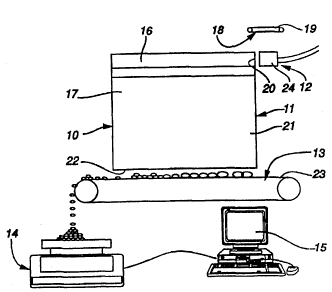
Referring to Figures 1 and 2, the device 10 accord-
ing to the present invention, comprises essentially a separa-
tion vessel 11 for particles comprising the granular product,
a separation means 12 for said particles, recovery means 13
for these particles, weighing means 14 and a data processing
device lS.
The separation vessel 11 is formed from a cylindri-
cal guide channel 16 open at its two ends, and from a lower
receptacle 17 closed at its two ends and disposed below the
guide channel. The channel 16 and the receptacle 17 communi-
cate over all their length.
The guide channel is associated with means 18 for
supplying said particles, these supply means comprising for
example a belt conveyor 19 arranged to transport particles of
the granular product to be separated from a source of parti-
cles (not shown) to a first end 20, a so-called downstream
end, of the guide channel 16.
The lower receptacle 17 is formed by two flat
parallel walls 21 spaced apart a distance less than the
maximum width of the guide channel 16 and greater than the
greatest dimension of the particles to be sorted. This
receptacle 17 comprises an open bottom 22 disposed above
- 21~1365
recovery means 13. These latter comprise an endless conveyor
23, extending over all the length of the vessel 11.
The separation means 12 comprises a movement
generator 24 disposed at the downstream end 20 of the guide
channel 16 and disposed such that it generates a substantially
homogeneous flow of fluid longitudinally in the canal. The
movement generator 24 can for example be a pump, a blower or
a source of water and its nature depends on the product to be
separated. It must be able to transmit a large part of the
energy of the fluid stream to the particles, without having
any chemical interaction with these particles.
The weighing means 14 are disposed below one end of
the belt conveyor 23 such that upon displacing this belt, a
portion of these particles that it carries will fall on said
weighing means.
The data processing means 15 is connected to the
weighing means 14 and is arranged to record the masses
measured by this weighing means as well as displacement of the
endless conveyor 23.
A separation device 10 described above is essential-
ly used for three different operations, namely, the production
of a reference curve, the qualification of a product and the
measurement of the particles which constitute a granular
product.
To produce a reference curve, one proceeds in the
following manner:
- 2191365
- a granular reference particle whose characteris-
tics are known, is introduced into the separation vessel 11;
- simultaneously, there is generated in the guide
channel 16 a substantially homogeneous and longitudinal fluid
flow, of constant amplitude. This flow is for example an air
flow;
- the endless belt conveyor 23 being immobile, all
the particles can be accumulated in the device.
The fluid flow transmits a portion of its kinetic
energy to the particles. Each particle receives a quantity of
kinetic energy which depends on different parameters such as
the transverse surface, which can vary at any moment, and the
frictional coefficient between the particles of the fluid.
These particles therefore have a speed having a horizontal
component due to the fluid flow and a vertical component due
to the earth's gravity. The particles follow a parabolic path
and fall on the recovery means 13 at positions depending on
the different parameters mentioned above. The fluid flux is
subject to a pressure drop within the guide channel 16, this
pressure drop being used to improve the separation of the
particles. The fluid therefore does not supply to the
particles a constant energy no matter what the location of the
guide channel in which these particles are located, but it has
an energy gradient.
- The conveyor belt 23 is advanced by a distance
corresponding to the desired measurement resolution;
2191365
- the particles that have fallen on the weighing
means 14 are weighed;
- this mass is recorded, as well as a positional
reference, in the data processing device 15;
- the particles are removed from the weighing means
14, the conveyor belt is again advanced and the particles have
that fallen on the weighing means are weighed. This operation
is repeated until there are no further particles on the
conveyor belt.
There can thus be established a reference curve such
as is illustrated in Figure 3, which is representative of the
distribution of the particles of a given reference product for
given measurement conditions.
When it is desired to classify a granular product,
the same process as above is followed, so as to obtained a
distribution curve of the particles of this product. This
distribution curve is then compared to the reference curve,
which permits observing the possible displacement of the peaks
of the distribution curve relative to the reference curve.
The displacement of the peaks can for example be a sign of
aging of the product, agglomeration or bonding of the parti-
cles. It can also signal dehydration or water absorption.
Finally, the third operation which can be carried
out with the separation device of Figures 1 and 2, namely, the
sorting of the particles forming a product, consists in
separating these particles into different classes depending on
21913~5
their position on the conveyor belt and using only the
fractions of interest.
The separation device as illustrated in Figure 4
differs from that of Figures 1 and 2 essentially by the
recovery means 31. These comprise a separation element 32
provided in the form of a container 33 disposed below the
bottom of the vessel between two positioning abutments 34.
This device is essentially used to separate particles of a
product of which only one fraction is of interest. The
container is disposed in a position such that the fraction of
interest of the granular product falls into this latter when
all of the particles pass through the separation vessel.
Thus, the container permits collecting a product whose content
in particles of interest is particularly high, whilst the
product falling on the recovery means beyond the container 33
has a content of particles of little or no interest.
The separation device 40 shown in Figure 5 comprises
three vibration generators 41 disposed along the guide channel
42 in the upper portion of this latter. These three vibration
generators give rise to a transverse acoustic wave in the
channel, these waves having each a separate frequency and/or
different amplitude. They have the object of modifying the
path of the particles passing in their immediate proximity.
The light particles passing one of these generators 41 will
have their path strongly diverted whilst the heavy particles
will be only slightly influenced by these acoustic waves.
Thus, the distribution of the particles on the recovery means
2191365
can be modified by addition of these vibration generators. A
container 43 is moreover placed below each of these generators
41 slightly offset forwardly, so as to recover the particles
in three distinct lots. It is possible to modify the ampli-
tude and frequency of the vibrations, as well as the speed of
flow of the fluid so as to obtain optimum separation.
In the separation device 50 illustrated in Figure 6,
three fluid sources 51 are disposed above the guide channel 52
so as to generate in this channel a vertical descending fluid
flow. These sources 51 of fluid have the same function as the
vibration generators 41 illustrated in Figure 5. The recovery
means 53 comprise two containers 54, 55 of which one, 54, is
open and connected to evacuation means (not shown) and of
which the other, 55, is closed. This device is particularly
adapted to separate the usable particles from a mixture of
particles. As in the embodiment shown in Figure 5, it is
possible to vary the speeds of the different flows, so as to
obtain the best separation possible. These speeds of flow are
determined experimentally as a function of the type of product
to be sorted and of the desired result.
The device according to the present invention can be
used in numerous fields for the separation, sorting, classifi-
cation and inspection of granular products. For each type of
use and for each form of desired result, the different
components of the device and particularly the generator of
movements and the recovery means must be suitable. Among the
numerous uses possible, can be cited several examples.
- 21913~S
In a production line in which is used a granular
product such as a food powder for example, it is desired to
control the stability of various parameters of the product,
these parameters being its composition, the size of the
particles which form it, their water content, etc. To do
this, it suffices to provide a curve representing the mass of
particles by transverse fractions on the belt conveyor and to
compare this curve to a reference curve. This type of
measurement permits continuous inspection of the quality of
the product. It is thus possible to react almost immediately
when the product does not respond to the desired criteria, as
shown by an offset or deformation of the distribution curve of
the product relative to the reference curve.
When it is desired to separate a usable fraction
from a mixture of particles containing a useless fraction,
such as seeds in the course of germination in a seed lot with
different degrees of maturity, there is disposed a separation
element on the recovery means. This separation element can be
constituted by a transverse wall or by a recovery vessel into
which fall the interesting fraction of the mixture. The
determination of the position of the wall or of the vessel
permits selecting the utilized fraction of the mixture.
The device according to the present invention can
for example also be used to separate gold bearing powder from
the rock which contains it. To this end, the rock is ground
into fine particles, then introduced into the device. In this
embodiment, the fluid circulating in the guide channel is
219-13~
water. Three vertical water jets are disposed at the top of
the vessel. These particles are entrained by the longitudinal
water flow. When they pass through the first vertical water
jet, the heavy particles have a high kinetic energy and their
path is substantially unaffected by the water jet. Less dense
particles on the other hand are driven to the bottom of the
vessel by the first water jet. When the particles arrive at
the second water jet, they have lost a portion of their
kinetic energy through loss of momentum. The second water jet
can thus capture the less dense particles. Finally, the third
jet captures the densest particles which can be recovered in
a separate container. The gold-bearing particles being the
densest, the first receptacle will contain a high proportion
of gold.
It is to be noted that the separation process of the
present invention is completely compatible with processes
presently practiced in the prior art. Thus, it is possible to
reuse the reference curves of the given products, established
according to other methods. This process moreover permits a
particularly fine and precise analysis of the granular
products. It is thus possible to refine the reference curves
of the prior art.
The separation process according to the present
invention moreover permits studying the friability of a
product, this study can be carried out by causing a lot of the
product to pass through the device, then subjecting this
product to compression and causing this same lot to pass
2 1 ~ 5
through the device. The comparison of the two distribution
curves of the particles permits characterizing the friability
of the product.
So as to be able to use such a device in a correct
manner, it is essential that the fluid flow circulating in the
guide channel be the least turbulent possible. This is
achieved very easily in the device according to the present
invention, because of the geometric shape of this device. The
fluid flow circulates essentially in the guide channel. This
flow is less affected by the presence of particles because
they pass through this channel with only a very short lapse of
time. The flow can be relatively less turbulent, even for
high speeds, which permits sorting large size particles.
The products used can for example be food powders,
vegetable seeds, mechanical members such as watch pieces,
mineral mixtures or pharmaceutical granules. The fluid used
to generate a flow can for example be a gas such as air or a
neutral gas, or a liquid such as water or mercury.
The guide channel can have an annular shape such
that the fluid circulates in a closed circuit in the device.
In this way, only a small quantity of fluid is necessary and
this is not wasted, which can be of interest in the case of an
expensive fluid or polluting fluid for example.
The width of the lower receptacle can be adjustable
so as to be matched to the dimensions of the particles to be
sorted.
- 219136~
The recovery means can be comprised by a conveyor
disposed perpendicular to the guide channel. This embodiment
is similar to the cases illustrated in Figures 4 and 5 in
which the recovery means comprise a container. These recovery
means can also comprise a container disposed between the
parallel walls of the vessel.
The process according to the present invention can
be used either only for separating particles forming the
granular product, or for separating and classifying them.
It is moreover possible to charge electrically the
guide channel so as to separate particles also having an
electrical charge, such as for example particles of loaded
polyethylene or loaded polyvinyl chloride.