Note: Descriptions are shown in the official language in which they were submitted.
WO 95133629 Y . ' PCTIUS95107060
t s ~ t
BaCKGROfIND OF THE INVENTION
, 1. Field of the Invention
The invention is a unique automotive hybrid powartrain design
that allows highly efficient use of energy generated by an
,integrated internal or external combustion engine. Tha field of
application is in propulsion systems for motor vehicles.
2. Th~ior Art
The growing utilization of automobiles greatly adds to
l0 the atmospheric presence of various pollutants including greenhouse
gases such as carbon dioxide. For this reason, there has been a
quest for approaches to improve the efficiency of fuel utilization
for automotive pawertrains. Current powertrains typically average
only about 10 to 15i thermal efficiency.
Conventional automotive powertrains result in significant
energy loss, make it difficult to effectively control emissions,
and offer limited potential to bring about major improvements in
automotive fuel economy. Conventional powertrains consist of an
internal combustion engine and a simple mechanical transmission
having a discrete number of gear ratios. Due to the inefficiencies
described below, about 851 to 90t of the fuel energy consumed by
such a system is wasted as heat. Only lot-15i of the energy is
available,to propel the vehicle, and much of this is dissipated as
heat in braking.
Much of the energy loss is due to a poor match between engine
power capacity and average power demand. The load placed on the
' engine at any given instant is directly determined by the total
road load at that instant, which varies between extremely high and
W095/33629 .. ~~;~~~~; ~.,4 ~ 7 PCf/US95107060
extremely low load. To meet acceleration requirements, the engine
must be many times more powerful than the average power required
to propel the vehicle. The efficiency of an internal combustion
engine varies significantly with load, being best at higher loads
near peak load and worst at low load. Since engine operation
experienced in normal driving is nearly always at the low end of
the spectrum, the engine must operate at poor efficiency much of
the time, even though some conventional engines have peak
efficiencies in the 35f to 40~ range.
another major source of energy loss is in braking. In
contrast to acceleration which requires delivery of energy to the
wheels, braking requires removal of energy from the wheels. Since
an internal combustion engine can only produce and not reclaim
energy, a conventional pawertrain is a one-way energy path.
Braking is achieved by a friction braking system, which renders
useless the temporarily unneeded kinetic energy of the vehicle by
converting it to heat.
The broad variation in speed and load experienced by the
engine in a conventional powertrain also makes it difficult to
effectively control emissions because it requires the engine to
operate at many different conditions of combustion. Operating the
engine at more constant speed and load would allow much batter
optimization of any emission control devices, and the overall more
efficient settings of the engine would allow less Euel to be
combusted per mile traveled.
conventional powertrains offer limited potential to bring
about improvements in automotive fuel economy except when combined
with improvements in aerodynamic drag, weight, and rolling
resistance. Such refinements can only offer incremental
improvements in efficiency, and can apply equally well with
improved powertrains.
2
W095133629 '~ , , , ., PCT1U595/07060
Hybrid vehicle systems have been investigated as a moans to
mitigate the foregoing inefficiencies. A hybrid vehicle system
provides a "buffer" between the power required to propel the
vehicle and the power produced by the internal combustion engine
in order to moderate the variation of power demand experienced by
the engine. The buffer also allows regenerative braking because it
can receive and store energy from sources other than the engine.
The effectiveness of a hybrid vehicle system depends on its ability
to operate the engine at peak efficiencies and on the capacity and
efficiency of the buffer medium. Typical buffer media include
electric batteries, mechanical flywheels and hydraulic
accumulators.
To use a hydraulic accumulator as the buffer, a hydraulic
pump/motor is integrated into the system. The pump/motor
interchangeably acts as a pump or motor. As a pump, the pump/motor
uses engine or "braking" power to pump hydraulic fluid to an
accumulator where it is pressurized against a volume of gas (e. g.,
nitrogen). As a motor, the pressurized fluid is released through
the pump/motor, producing power.
There are two general classes of hydraulic hybrid vehicle
systems. A "series" system routes all of the energy produced by
the engine through a fluid power path and so it is the fluid power
side that experiences the variable road load. This improves
efficiency because the efficiency of the fluid power path is not
as sensitive to the power demand variations, and because the engine
is thus decoupled from road load, allowing it to operate at peak
efficiency or be turned off. Series systems are relatively simple
in concept and control, but have less efficiency potential than
other systems because all energy must be converted to fluid power
and back to mechanical power to propel the vehicle. They also
depend on frequent on/off operation of the engine for optimum
, efficiency. "Parallel" systems split power flow between a direct,
almost conventional mechanical drive line and a fluid power path.
3
W0 95133629 ~: ~: ,~ ~.. (y (~.,1 PGT1f1S95107060
Thus, some of the energy is spared the conversion to fluid power
and back again. Tha most common context for such systems era in
a "launch assist" mode where the hydraulic system serves mainly to
store braking energy and to redeliver it to assist in the next
vehicle acceleration. The parallel system, because it requires ,
both a conventional and a hydraulic power path to the wheels, tends
to be more complex than the series system and more difficult to ,
control ~or smoothness. Depending on the specific design, both
series and parallel systems allow some reduction of engine siae but
both still tend to require a relatively large engine.
For example, U.S. Patent 4,223,532 (September 23, 1980),
issued to Shiber, discloses a hydraulic hybri8 transmission system
which utilises two pump/motors and is based on a theory that
encourages intermittent engine operation.
ett~~ny OF THE TNVENTION
hccardingly, it is an object of the present invention to
provide a hybrid powertrain system which allows for significant
reduction of size of the vehicle's internal combustion engine.
It is a lurther object of the present invention to provide a
powertrain system which allows the vehicle's internal combustion
engine to be constantly operated at near peak efficiency.
It is yet a further object of the present invention to provide
a hybrid propulsion system wherein presently unneeded power
generated. by the internal combustion engine can be stored in a
"buffer" for use to produce driving farce (1) at such times when
the internal combustion engine alone is insufficient to provide the
output torque demanded of the vehicle and (2) at times of very low
power demand when engine operation would be inefficient, e.q. in
a traffic jam.
4
CA 02191447 2002-05-02 ~~ y
Still another object of the present invention is to
provide a powertrain design that allows a more highly
efficient use of energy generated by the internal combustion
engine than heretofore possible.
Still another object of the present invention is to
provide a hybrid powertrain propulsion system which allows for
extreme variations in road load while maintaining high
efficiency.
The present invention provides a unique "parallel" hybrid
propulsion system and method of operation which meet the
above-stated objectives. Specifically, the hybrid powertrain
vehicle of the present invention includes a vehicle frame
supported above a road surface by drive wheels rotatably
mounted thereon. A primary engine, e.g. an internal or
external combustion engine, mounted on the vehicle frame
provides output engine power and an output shaft in a
conventional manner. A power storage device is also mounted on
the vehicle frame to serve as a "buffer", i.e. for storing and
releasing braking and "excess" engine power. A first
drivetrain serves to transmit the engine power to the drive
wheels and includes a continuously variable transmission (CVT)
having the usual movable pulley of variable effective diameter
(or other multiple gear ratio transmission).
In the preferred embodiment, a reversible fluidic
displacement means or "reversible pump/motor," is interposed
between a fluid pressure accumulator and the first drivetrain
to output motor power to the first drivetrain, driven by the
accumulator fluid pressure in a first mode and to operate as
a pump, driven by the first drivetrain, to store fluid
pressure in the accumulator in a second mode. In other
embodiments the reversible means could be, for example, the
combination of a storage battery, generator/alternator and an
electric motor.
5
CA 02191447 2005-02-24
Therefore, in one aspect c~f the present invention,
there is provided a hybrid powe:rtrain vehicle comprising:
a vehicle frame;
drive wheels rotatably mounted on said vehicle frame;
s a primary engine, mounted on said vehicle frame, for
providing engine power by rotation of an output shaft;
power storage means, mounted on said vehicle frame, for
storing and releasing power generated by said primary
engine;
to first drivetrain means fox' transmitting said engine
power to said drive wheels, said first drivetrain means
including a transmission having adjustable speed input and
output;
reversible means for selectively, while driven by said
is rotation of said engine in a first mode, transmitting said
engine power to said power storage means so as to increase
the load on said primary engine when power demand is less
than that required for operation of said primary engine
within a range of optimum efficiency and, operating as a
2o motor in a second mode, transmitting stored power from said
power storage means to said first drivetrain means where,
when the power demand is greater than that deliverable by
said primary engine operating within the range of optimum
efficiency, said transmitted stored power is added to said
2s engine power, whereby the primary engine is constantly
operated at near peak efficiency in at least said first and
second modes;
second drivetrain means, in parallel with at least a
portion of said first drivetrain means, connecting said
3o reversible means to said first drivetrain means, for, in
said second mode, transmitting said stored power to said
first drivetrain means and for, in said first mode,
-~~
CA 02191447 2005-02-24
transmitting said rotation of raid engine to said reversible
means for transfer of a portion of said engine power to said
power storage means simultaneously with transfer of the
remainder of said engine power to said drive wheels;
vehicle speed sensor mean:> for sensing vehicle speed;
stored power sensor means for sensing a quantity of
power stored within said power storage means;
power demand sensing mean:. for sensing power demanded
of the vehicle by a driver;
to comparing means for comparing said sensed quantity of
stored power with a predetermir~ed minimum amount of stored
power and generating a demand ~;ignal upon determination that
said sensed quantity is below :aid predetermined amount;
power output determining means for determining an
i5 additional increment of power in accordance with said demand
signal and for determining an engine output power as a sum
of the sensed power demand and the additional increment of
power;
engine speed control means for controlling speed of
2o said rotation of said output shaft by changing the input
speed of said transmission responsive to a transmission
signal;
engine speed determining means for determining an
engine speed of optimum efficiency in accordance with said
25 determined engine output power and said sensed vehicle speed
and for outputting the transmission signal, indicative of
the determined engine speed, to said engine speed control
means;
engine load control means for controlling said
ao engine power by controlling fuel feed to said primary engine
responsive to engine speed; and
mode control means for converting operation of said
5-b
CA 02191447 2005-02-24
reversible means between said first and second modes
responsive to the demand signa7_.
In another aspect, the present invention provides a
method for controlling a vehic7.e equipped with a hybrid
powertrain propulsion system ir~cluding drive wheels,
reversible drive means, a prim~~ry engine for rotatably
driving said drive wheels and :.aid reversible drive means
simultaneously in parallel, pourer storage means for storing
engine power generated by said primary engine, a
to transmission having adjustable speed input and speed output
and engine speed control means for changing the input speed
of said transmission, said metr~od comprising:
sensing vehicle speed;
sensing a quantity of power stored within the power
storage means;
sensing power demanded of the vehicle by a driver;
feeding power from the pov~~er storage means, through the
reversible drive means, utilizing the reversible drive means
as a motor in a first mode for driving said drive wheels
2o responsive to a signal indicating a demanded power above
that deliverable by the primary engine operating within a
range of optimum efficiency, said feeding of power from the
power storage means being simultaneous with and in addition
to transfer of power from the primary engine to the drive
wheels;
simultaneously (1) transmitting a portion of the output
power of the primary engine into said power storage means,
using said reversible drive means as a pump or generator in
at least a second mode, responsive to a sensed quantity of
3o stored power lower than a predetermined value when the power
demand is below that deliverable by the primary engine
operating within the range of optimum efficiency and (2)
5_c,
CA 02191447 2005-02-24
transmitting the remainder of t:he output power of the
primary engine to the drive whE:els;
comparing the sensed quantity of stored power with a
predetermined minimum value and generating a demand signal
upon determining that the sensed quantity of stored power is
below the predetermined minimum value;
determining an additional output power in accordance
with the demand signal and determining an engine output
power as the sum of the sensed power demand and the
to additional output power;
controlling the rotary speed of the primary engine by
changing the input speed of the: transmission responsive to a
transmission signal; and
determining an engine speed of optimum efficiency in
i5 accordance with the determined engine output power and the
sensed vehicle speed and outputting the transmission signal
in accordance with the determined engine speed, thereby
constantly operating the primary engine at near peak
efficiency in said first and second modes.
2o In a further aspect, the Fresent invention provides a
hybrid powertrain vehicle comprising:
a vehicle frame;
drive wheels rotatably mounted on said vehicle frame;
a primary engine, mounted on said vehicle frame, for
25 providing engine power as rotation of an output shaft;
a fluid pressure accumulator, mounted on said vehicle
frame, for storing and releasing fluid pressure;
first drivetrain means for transmitting said engine
power to said drive wheels, said first drivetrain means
3o including a continuously variable transmission having at
least one pulley of variable effective diameter;
reversible fluidic displacement means for, in a first
5-d
CA 02191447 2005-02-24
mode, operating as a motor flu=.dically driven by fluid
pressure released by said accumulator, to output motor power
to said first drivetrain means where, when the power demand
is greater than that deliverab7.e by said primary engine
s operating within a range of optimum efficiency, said motor
power is added to said engine ~>ower and for, in a second
mode, operating as a pump drivE:n by said rotation of said
engine, through said first driz~etrain, to store said fluid
pressure so as to increase the load on said primary engine
to when power demand is less than that required for operation
of said primary engine within the range of optimum
efficiency, thereby constantly operating the primary engine
at near peak efficiency in said first and second modes;
second drivetrain means, connecting said fluidic
15 displacement means to said first drivetrain means, for, in
said first mode, transmitting said motor power to said first
drivetrain means and for, in said second mode, transmitting
engine power to said fluidic displacement means;
vehicle speed sensor means for sensing vehicle speed;
2o pressure sensor means for sensing the fluid pressure
within said accumulator;
power demand sensing means for sensing power demanded
of the vehicle by a driver;
comparing means for comparing said sensed fluid
as pressure with a predetermined minimum fluid pressure and
generating a demand signal upon determination that said
sensed fluid pressure is below said predetermined fluid
pressure;
power output determining means for determining an
3o additional increment of power in accordance with said demand
signal and for determining an engine output power as a sum
of the sensed power demand and the additional increment of
5-e:
CA 02191447 2005-02-24
power;
engine speed control mean: for controlling rotary speed
of said output shaft by changing the effective diameter of
said pulley responsive to a tr~~nsmission signal;
engine speed determining means for determining an
engine speed of optimum efficiency in accordance with said
determined engine output power and said sensed vehicle speed
and for outputting the transmi:;sion signal, indicative of
the determined engine speed, to said engine speed control
to means;
engine load control means for controlling said engine
power by controlling fuel feed to said primary engine
responsive to engine speed; anc.
mode control means for cor..verting operation of said
fluidic displacement means bet~n~een said first and second
modes responsive to the demand signal and for varying the
displacement of said fluidic displacement means responsive
to the sensed fluid pressure.
In yet another aspect of the present invention, there
2o is provided a method for contrclling a vehicle equipped with
the hybrid powertrain propulsion system including drive
wheels, a primary engine for powering the drive wheels, a
reversible fluidic displacement means, an accumulator for
accumulating fluid pressure, a continuously variable
transmission having a moveable pulley of variable effective
diameter and a controller for mechanically moving that
pulley to change the effective diameter, said method
comprising:
sensing vehicle speed;
3o sensing fluid pressure within the accumulator;
sensing power demanded of the vehicle by a driver;
feeding fluid pressure fro~n the accumulator, through
5-f'
CA 02191447 2005-02-24
the reversible fluid displacement device, to utilize the
reversible fluid displacement device as a motor in a first
mode for driving said drive wheels responsive to a signal
indicating a demanded power above that output by the primary
engine operating within a range: of optimum efficiency, said
feeding of power from the power storage means being
simultaneous with and in addition to transfer of power from
the primary engine to the drive: wheels;
pumping fluid pressure into the accumulator, using a
to portion of the output power of the primary engine to drive
the reversible fluid displacement means as a pump in a
second mode, responsive to a sensed fluid pressure lower
than a predetermined value where the power demand is below
that deliverable by said primary engine operating within the
range of efficiency;
comparing the sensed fluic. pressure with a
predetermined minimum fluid pre sure and generating a demand
signal upon determining that tr.e sensed fluid pressure is
below the predetermined low fluid pressure;
2o determining an additional output power in accordance
with the demand signal and determining an engine output
power as the sum of the sensed power demand and the
additional output power;
controlling the rotary speed of the primary engine by
changing the effective diameter of the moveable pulley
responsive to a transmission signal; and
determining an engine speed of optimum efficiency in
accordance with the determined engine output power and the
sensed vehicle speed and outputting the transmission signal
3o in accordance with the determined engine speed, thereby
constantly operating the primary engine at near peak
efficiency in said first and second modes.
5-c~
CA 02191447 2005-02-24
A second drivetrain serve~~ to connect the power storage
device to the first drivetrain thereby defining a "parallel"
propulsion system.
Control of the propulsior~ system is provided for, in
part, by three sensors, i.e. a vehicle speed sensor, a power
storage sensor, e.g. a pressL.re sensor for sensing fluid
pressure within the accumulator and a torque (or power) demand
sensor for sensing torque (or ~~ower) demanded of the vehicle
by the driver, e.g. a sensor fo== "throttle" pedal position or
to "accelerator" pedal depression. A microprocessor includes
comparing means for comparing the sensed value of stored power
with a predetermined minimum value for stored power and for
generating a demand signal upon a determination that the
sensed value for stored power is at or below the predetermined
minimum value. The microprocessor also includes a torque
output determining means for dei;ermining an additional torque
in accordance with the demand ;signal and for determining an
engine output torque as the sum of the sensed torque demand
and the additional torque. The microprocessor also includes an
2o engine speed determining processor for determining an engine
speed of optimum efficiency in ~iccordance with the determined
engine output torque and the ,sensed vehicle speed and for
outputting a transmission signal, indicative of the determined
engine speed. An engine speed control means controls the
rotary speed of the output shaft of the engine by changing the
gear ratio of the transmission.. In the preferred embodiment
this involves changing the effective diameter of the movable
pulley of the CVT, responsive to the transmission signal
output by the engine speed determining processor. An engine
load controller controls engine power by controlling the fuel
feed to the primary combustion engine responsive to the engine
speed. A mode controller serves to switch the power storage
device between power storing and power release modes. In the
preferred embodiment the mode controller serves both to
convert operation of the fluid displacement means between the
first and second modes of operation, responsive to the
6
i I
CA 02191447 2002-05-02
demand signal, and to vary the displacement of the fluid
displacement means responsive to the sensed fluid pressure.
Optionally, a secondary, e.g. internal combustion, engine
is mounted on the vehicle frame to provide for additional
engine capacity which might be needed, for example, to climb
a particularly steep grade. When a secondary engine is mounted
on the vehicle, a secondary engine clutch is interposed
between the output of the secondary engine and the first
drivetrain for matching the output speed of the secondary
engine with the output of the primary engine.
The propulsion system of the present invention optionally
further includes a free wheel clutch interposed between the
transmission (CVT) and the drive wheels for disengaging the
drive wheels from the first drivetrain responsive to a signal
indicating zero power demand.
In the present invention the propulsion system is
controlled by sensing vehicle speed, sensing fluid pressure
within a fluid pressure accumulator and sensing power demanded
of the vehicle by the driver. A reversible fluidic
displacement device (pump/motor) is switched between a pump
mode and a motor mode responsive to torque demand and
available fluid pressure stored in the accumulator. The sensed
fluid pressure is compared with a predetermined minimum fluid
pressure and, if determined to be below the predetermined
fluid pressure, a demand signal is generated. The additional
torque necessary for adequately raising fluid pressure is
determined in accordance with the demand signal and an engine
output torque is determined as the sum of the sensed torque
demand and the determined additional torque. An engine speed
controller controls the rotary speed of the output shaft by
changing the effective diameter of a movable pulley of the CVT
responsive to a transmission signal. An engine speed
processor, in turn determines an engine speed of optimum
efficiency in
7
CA 02191447 2005-02-24
accordance with the determined engine output torque and the
sensed vehicle speed and ou~=puts a transmission signal
indicative of the determined er.~gine speeds. The output power
of the internal combustion engine is controlled by controlling
s fuel feed thereto responsive tc~ the engine speed.
In contrast to the prior art, the present system requires
only one pump/motor in the primary drivetrain and uses the
hydraulic subsystem in such a ~n~ay as to utilize a very small
prime engine and keeps the engine on as much as possible.
to The invention is a unique 1-ype of "parallel" system, but
can operate in a series configuration as well. The system of
the present invention includes ,~ very small engine sized near
the average power requirement rather than the peak power
requirement. The hydraulic subs:~rstem acts as a power-trimming
is device to "trim" the power demand experienced by the engine.
That is, the hydraulic subsystem's main purpose is to keep the
engine operating as close as po;~sible to its peak efficiency,
by placing additional load on the engine at times of low
propulsion power demand and delivering additional power at
2o times of high or peak propulsion power demand. In the present
invention a single hydraulic ~ump/motor and an accumulator
achieve both functions. To p=_ace additional load on the
engine, the engine is run at a power level corresponding to
peak efficiency and the excess power is routed through the
2s hydraulic pump/motor (operatung as a pump) into the
accumulator where it is stored with very little energy loss.
To deliver additional power, the stored energy is discharged
to the powertrain through the h~,~draulic pump/motor (operating
as a motor).
3o In its simplest configuration, a clutching arrangement
between the transmission and wheels allows free-wheeling when
no power is needed from the powertrain. However, for
simplicity, no clutching is provided between the engine,
hydraulic pump/motor, and transmission. Therefore, the engine
3s may occasionally be motoring
8
W095133629 , ~ ~ ~ .~ ~ PCflUS95107060
while the pump/motor is charging the accumulator during
regenerative braking or when delivering small amounts of power by
itself. This creates a drag on the power train that reduces
efficiency somewhat. The friction losses associated with this
arrangement are minimal due to the small displacement of the
internal combustion engine and the small amount of time in this
mode of operation.
The present invention includes at least two configurations !or
hydraulic regenerative braking. In the first embodiment, friction
brakes are activated first, after which hydraulic braking is phased
in. This method reduces the sophistication o! the controls that
would be needed to effect a smooth routing of power from the
wheels, and allows safety in case of a hydraulic system failure.
In the second embodiment, hydraulic braking occurs first with
friction brakes added as a backup system. This second embodiment
is somewhat more complex to control, but is the preferred
embodiment because it maximizes the recovery o! braking energy.
When accelerating from a stop, the engine provides power to
the wheels through the non-hydraulic portion of the drivellne. If
more power is needed than the engine can provide, additional power
is supplied by the pump/motor acting as a motor. Tha accumulator
is of sufficient size to allow this additional power to be provided
twc or more times in succession. Accumulator capacity Eor at least
one acceleration is needed for regenerative braking and capacity
!or another is needed as backup in case a stop does not allow
regenerative braking.
When cruising speed is reached and power demand drops o!f to
a low level, the engine output matches the road load because the
engine is small enough that its peak efficiency corresponds to
loads characteristic of average road load. If more power is
required of the engine in order to maintain peak operating
efficiency, an additional load is provided by charging the
9
WO 95/33629 ', :, ~ ~ y 914 4 7 PCT~S95107060
accumulator through the purop/roctor acting as a pump. It the
accumulator can accept no more charge, the pump/motor is sat to
zero displacement and the engine merely runs at a reduced power
output. Since the engine i5 sized close to the average power load
during cruising, there is little or no sacrifice in efficiency at
this setting. The engine can also be turned off and the
accumulator can drive the pump/rootor acting as a motor, it the load
is very low as would occur in low speed, stop and go traffic.
When braking occurs, and if there is sufficient unused storage
capacity reserved in the accumulator, regenerative braking occurs
where the pump/motor acts as a pump to charge the accumulator. If
there is nd capacity left in the accumulator, friction brakes are
used. The system is managed so that there will normally be
sufficient capacity available for regenerative braking.
If sudden acceleration is required during a cruising period,
this may be provided by boosting the output of the engine along the
test efficiency line. After the maximum efficient engine power
output point is reached, the hydraulic subsystem is activatwd to
retrieve additional power from the accumulator via the pump/motor.
When the car creeps along at a very low speed, as in a traffic
jam, the engine is turned off and the pump/motor and accumulator
are used to drive the car. This is better than using the engine
alone in such a mode because a pump/motor can operate at a good
efficiency even at low speeds and low power demands.
Through proper choice of component sizes and control system
optimisation, the system can be designed to optimize various goals.
- For instance, one could minimize the chance of either: a)
encountering a fully charged accumulator when regenerative braking
energy becomes available, or b) depleting the accumulator by several
rapid accelerations without chance to recharge the accumulator.
WO 95/33629 21914 4 7 P~~S95107060
'-- T° r r, r .~.
Rhe use of a~ $mall '~angine supplemented by an accumulator of
finite energy storage capacity presents a difficulty in ascending long
grades. Just as with acceleration, ascending a grade requires an
unusually large amount of power, but unlike an acceleration a long
grade requires this power for an extended period of time. Since the
theory of operation of the invention is to provide a large portion of
~ acceleration power by means of a hydraulic accumulator, a long grade
would deplete the accumulator in short order and the vehicle would be
left with insufficient power.
As an alternative to an extremely largo accumulator capacity, a
second engine, which can be inexpensive and of only moderate
durability due to its occasional use, may be clutched in to supplement
the power of the primary engine and pump/motor for an unlimited time.
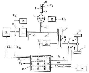
Fig. 1 is a schematic diagram of a first embodiment of a vehicle
equipped with a hybrid powertrain propulsion system of the present
invention.
Figs. 2a, 2b, 2c and 2d are graphs of engine load versus engine
speed in various modes of operation of the system depicted in Flg. 1.
Fig. 3 is a schematic illustration of a vehicle equipped with a
second embodiment of a hybrid powertrain propulsion system in
accordance with the present invention.
Fig., 4 is a schematic illustration of a vehicle equipped with a
third embodiment of a hybrid powertrain propulsion system in
: accordance with the present invention.
Fiq. 5 is a schematic illustration of a vehicle equipped with a
fourth embodiment of a hybrid powertrain propulsion system in
accordance with the present invention.
11
WO 95133629 PCTIU595107060
.. , .. > _. .
f~ , '.
~. j, . ~ ..
2191447
Fig. 6 is a logic flow diagram for control of operation of a
vehicle by a microprocessor in accordance with the present invention.
Fig. 1 illustrates an embodiment of the present invention
suitable for driving a three to four thousand pound vehicle. ,1 very
small internal combustion engine 1 (e.g. 20 hp) provides energy to the
system. The energy is transmitted along the driveshaft 2, which
constitutes a first drivetrain, and can be routed either to the
transmission 3, in this embodiment a continuously-variable
transmission (CVT), or to the pump/motor 7 (acting as a pump in the
second mode) or both. The pump/motor 7 is a reversible hydraulic
displacement device, e.g. a awash plate pump in which flow reversal
is inherent to the pump or a bent axis pump wherein flow reversal is
by valuing external to the pump, capable oI operating either in a
first mode as a motor or in a second mode as a pump. The pump/motor
7 has a variable displacement. Energy routed to the pump/motor 7
(acting as a pump) is used to pump fluid to the accumulator 6,
pressurising the fluid g against a volume of gas d~ Energy routed to
the transmission flows along the lower driveshaft 9 past the freewheel
clutch 4 to the wheels 5. The pump/motor 7 is switched between its
first and second modes and its displacement is varied by a pump/motor
controller 20, responsive to a signal FPs.
When_the power demanded at the wheels 5 is larger than the power
deliverable by the engine 1 alone. additional power is provided by the
~. pump/motor 7 (acting as a motor in the first mode). In this mode the
pressurised fluid in the accumulator 6 flows to the pump/motor 7
(acting as a motor), creating mechanical power that flows along the
drive shaft 30 to driveshaft 2, to the transmission 3 and flows to the
wheels as already described. The hydraulic accumulator 6, pump/motor
12
W095/33629 w t' t~'~t~t~~~ ~ PCTIUS95/07060
7 and shaft 30 constitute a second drivetrain, °parallal" to the first
drivetrain.
Indicated at 26 is an angina control device, a.q. a tool
injection pump, which controls fuel feed to the engine 1, responsive
to a signal Es which is a function of engine speed. Signal Ea may be
computed by processor 18 or may be a signal received directly troa an
rpm sensor 40.
Tha control hardware for operation of the vehicle includes a
verticle speed sensor, e.g. rpm sensor 12, which detects the rotational
speed of the drive shaft downstream of the freewheel clutch 4, a
pressure sensor 16 for detecting the pressure within the fluid
pressure accumulator 6 and generating a signal Pa rapresentativa of
the detected pressure end a power demand sensor 14, e.g. a sensor for
detecting position of the "accelerator pedal. A first processor 42
receives the signal Ps representative of the fluid pressure detected
by sensor 16 and compares that detected fluid preseura with a
predetermined minimum fluid pressure and generates a demand signal FPS
upon determination that the sensed fluid presaurn is below the
predetermined minimum fluid pressure. That demand signal FPS is sent
to the pump controller 20 for conversion o! the pump/motor 7 to itta
second mode for operation as a pump, to store energy in the
accumulator 6 in the form of fluid pressure.
.1 second processor 4a determines an additional power in
accordance with the demand signal FPS and an engine output power am
the sum of the power demand Sensed by 14 and the determined additional
power. A~third processor 46 determines the engine spaced of optiaum
efficiency in accordance with the determined total engine output
power, and with the sensed vehicie speed outputs a transmission signal
Ts, indicative of the determined optimum engine speed to the engine
speed controller 24. Controller 24 regulates engine speed responsive
to the signal Ta by changing the effective diameter of pulley 22 of
the CVT 3. Processors 42, 44 and 46 may optionally be combined into
13
R'O 95133629 -- , ,, - .;~. ~f9;1.-4 4 7 PCT~S95107060
.- ~ i ~ 1 :a
a single microprocessor 18 including a memory 48. The signal Ts is
determined by reference to a two dimensional map stored in memory 48
wherein values for optimum efficient power and engine speed are
-correlated. Knowing the desired engine speed and the vehicle speed
from sensor 12, signal Ts is computed. This control system is
likewise applicable to the other embodiments described hereinbelow.
T.n- optional secondary engine 1o can provide yet additional
reserve power. In this case an electronically controlled clutch 11
is engaged through which the power from engine 10 feeds into the
system. The secondary engine 10 provides backup power for severe or
repeated accelerations and for continuous operation to maintain speed
up long and/or steep grades. The secondary engine 10 and clutch 11
can be installed as shown (to supply power to the drive shaft 27 or
to supply power to drive shaft 9 directly. The engine 10 may be
electronically started and clutch 11 engaged responsive to a signal
SES generated as a function, for example, of the sensed "accelerator
pedal" position and detected accumulator fluid pressure. The clutch
11 serves to engage the secondary engine at the output speed of tho
primary engine. The primary engine 1 and the secondary engine 10, in
combination, might be regarded as the functional equivalent of a
variable displacement engine.
When Zero power is demanded at the wheels, the vehicle is changed
over to a coasting mode, responsive to a signal Cs from the
microprocessor 18, by disengagement of the freewheeling clutch 4. In
this manner the vehicle is isolated from rotational friction losses
in the drivetrain so that ail of the kinetic energy of the vehicle
is availaple for overcoming rolling resistance and aerodynamic
drag. The clutch 4 is normally engaged and is disengaged only when
. zero power demand is detected by sensor 14.
When the driver brakes, regenerative braking occurs. Kinetic
energy is transferred from the wheels 5 past the clutch 4 through
the transmission'3 along the drive shaft 2 into the pump/motor 7
14
WO 95133629 ~ PCTIUS95I07060
~° r
+~~ i v S
(acting as a pump). The pump/motor 7 pressurizes fluid and thereby
stores the energy in the accumulator 6 in the same manner as
described above.
Through fluid pressure in accumulator 6, the pump/motor 7,
operating in its first mode as a motor mny be used to start engine
1, thereby eliminating need for a conventional starter motor.
The operation of the invention will be more clearly understood
in reference to FIGS. 2A-2D. In the following discussion the term
~~optimum efficiency" refers to a range of speed and load, i.e.
(power) at which the efficiency of the engine 1 is deemed reasonably
near its optimum efficiency, between points A and 8.
Fig. 2A is a graph which represents instances (Mode 1) when the
power demanded is greater than that deliverable at optimum
efficiency by the engine 1 (point B) in the embodiment of Fig. 1.
In this case, that portion of load which exceeds 8 is provided by
the pump/motor 7 (acting as a motor), while the engine 1 provides
the rest. In embodiments where the engine and pump/motor shafts ate
not clutched or geared, the engine 1, pump/motor 7, and
transmission 3 input shaft would operate at the same speed. A
clutching arrangement or a gear reduction could be incorporated
therein without changing the basic function of this mode.
Fig. 2B illustrates the operation of the system of Fig. 1 in a
mode 2, i.e. when power demanded of engine 1 is within the range of
optimum efficiency (between power levels A and 8). This power
demanded pf engine 1 is determined by microprocessor 18 considering
power demanded by driver 14 and whether power should be supplied to
or extracted from the accumulator 6. If there is no need to
replenish the accumulator 6, all of the power is provided by the
engine 1, and the pump/motor 7 is stroked to zero displacement
(i.e., neutral position) by controller 20 where it neither pumps
fluid into the accumulator 6 nor provides power to the system.
W095/33629 . . r. ~ -- PCT/US95/07060
~,~,g ~.~47
Fig. 2C illustrates the situation where the engine 1 can
satisfy the driver power demand, and there is need (i.e., the
accumulator energy level has reached a predetermined minimum level,
but the engine 1 can operate at an optimum power level, point (b))
or desire (i.e., need to operate the engine at its optimum
efficiency as indicated by driver power demand point (a)) to
replenish the accumulator (mode 3j. While road load demanded is
represented by either of the points (aj or (bj shown in Fig. 2C, the
power output of the engine is increased along the optimum efficiency
line to a point at which sufficient excess power is generated,
illustrated here by the point (cj. The excess power that does net
go to road load is fed into the pump/motor 7 (acting as a pump) which
stores it in the accumulator 6 for future Mode 1 or Mode 4 events.
FIG. 2D illustrates mode 4 wherein an unusually small road load
is experienced. In this case, the engine cannot deliver such a small
amount of power at acceptable efficiency and significant pressure
exists in the accumulator 6. The fuel flow to the engine 1 is turned
off, and the pump/motor 7 (acting as a motor) provides power by
itself.
Regenerative braking can be thought of as an extension of Mode
4 (Fig. 2D), in which power demand is zero and the vehicle must
decelerate at a rate greater than rolling resistance and aerodynamic
drag would provide. The driver activates the brakes, which in turn
activate the pump/motor 7 (acting as a pump) which pressurizes fluid
as previously described using the vehicle's kinetic energy taken
through the drive shatt 2, transmission 3 and lower drive shaft 9.
This results in n deceleration similar to that caused by friction
braking, but the energy is saved in the accumulator 6 rather than
discarded.
,1n aitarnate embodiment adapted for operation which is expected
to involve more extensive stop and go driving is shown in Fig. 3.
16
W095/33629 ~' f,~' ~'9~ ~~4 4 7 pCT/US951D7060
In continual stop and go driving, a mode is invoked in which the
pump/motor directly drives the vehicle without assistance from ttw
engine. In this case a clutch 8 is providnd between the angina 1
and pump/motor 7 so as to disconnect the angina 1 in thin mode and
prevent friction asaociatad with operation o! the engine 1.
Yat another embodiment is shown in Fiq. 4, wherein a second
pump/motor 13 is provided between the transmiaaion and the wbaals.
This configuration would allow regenerative braking energy to proceed
through the second pump/motor 13 directly to the accumulator 6 without
incurring Frictional losses in passing through the transmission 3.
It the drag of the second pump/~tor 13 when in neutral is
sufficiently low, the second pump/motor 13 can stay on line directly
geared to the wheel drive s during all modes of driving. An option
to eliminate this ~in neutral~ drag would be to add a clutch between
the second hydraulic pump/motor 13 and the wheel drive 9. Since the
second pump/motor 13 can also provide power to the whanls in
acceleration and cruising modes, it allows the sixa of the lust
pump/motor 7 to be reduced. The smaller size of pump/motor 7 allows
the pump/motors to be selectively operated so as to batter match tM
30 size of the chosen motor to the power being demanded by tile wheels,
improving average efficiency. This is especially important for
urban driving where low and modest accelerations are frequent driving
modes and a smaller pump/motor 7 can supplement thn primary engine 1
more efficiently for small power increments than a larger pump/motor.
Tha addition of the second pump/motor 13 to handle high acceleration
rates and steep, eutnnded grades would also allow a significantly
smaller transmission, which is especially important for CUTS. For
steep grades, engine 10 could be activated and the pump/motor 7 could
operate as a pump driving the pump/motor 13 as a motor.
. Alternatively, a puap could be attached to engine 10, eliminating
clutch 11, to supply sustained power through pump/motor 13 ae a motor.
Another embodiment shown in Fig. 5 includes the second angina 10
clutched directly into the drive shaft 9 either upstream or downstream
17
W095133629 f, r- ..2,;.~ ~~-4 PCTIU&95/07060
f~ ; : c .:.
of the :rae wheel clutch 4, rather than behind the priau-y angina 1
as is the embodiments of Figures 1, 3, and 4. This arsanqeseat allows
the energy produced by the second engine 10 to pass directly to the
wheels 5 without incurring losses in the upstream components o! the
drive line, and allows a smaller transmission 3 and, if downstream,
a analler free wheel clutch 4. In either location, the second engine
supplies power far various purposes, including but not nocesaarily
limited to providing additional power for sustained hill-climbing,
providing additional acceleraticn powr during times of extremely hard
10 acceleration, providing emergency launching power in the case of
accumulator depletion, providing backup power for normal accelaraiioa
in order to alloy a reduced accumulator or pump/motor size, and for
selective operation so as to batter match the sins o! the chosen
engine to the road load demand.
Ona possible modification of the embodiment shown in Fiq. 3 would
be to delete the transmission 3 and launch the vehicle with the
pump/motor 7 through appropriate use of the free wheel clutch a.
A possible modification at the embodiment shown in Fiq. a would
be to delete the transmission 3 (and optionally clutch 12) and add a
clutch between the pump/motor 13 and the wheel drive 9. Tho vehicle
would be launched with either the pump/matar 7 (retaining clutch B)
or the pump/motor 13. At vehicle speeds above a specified minimum
(n. g. 20 miles per hour), engine 1 would be engaged and provide direct
shaft power, and operation would proceed as previously described.
This configuration would eliminate any risk oI accumulator pressure
depletion.
The logic flow for control by microprocessor 18 will now be
described with reference to Fiq. 6 0! the drawings. Fig. 6 is a
flow chart showing the flow of control processing by microprocessor
or computer unit 18. At step S1 a determination is made in
accordance with a signal from brake sensor 50 as to whether or not
brakes are engaged. I! the brakes era eaqaged (Y), the engine 1 is
18
WO 95/33629
Y, ~ ~ ~
,j- ~ ~ ~
PCT/US95107060
i
shutoff or disconnected to allow for regenerative braking
with
pump/rootor 7 operating as a pump to convert the energy
of the
braking into fluid pressure stored in accumulator 6.
At step S2 a
determination is made as to whether or not braking in
addition to
the regenerative braking is required. If required, friction
brakes
are engaged. In step 57 a determination is made, in
accordance with
the signal from sensor 14, as to whether or not power
is demanded by
the driver. If no power is demanded, processing continues
to step
S4 where accumulator pressure, determined as a function
of the
signal from sensor 16, is compared with a predetermined
minimum
value for accumulator pressure and, if below that predetermined
value, the engine is allowed to remain running with
pump/motor 7
operating as a pump to convert the engine power into
stored energy
in the form of fluid pressure. It the pressure comparison
of step
S4 determines that the sensed fluid pressure is abOVe
the
predetermined minimum, the engine is shut-otf or disconnected
and
the control processing cycle is restarted. If a determination
is
made in step S3 that power is demanded by the driver,
the control
processing proceeds to step S5 wherein a determination
is made as to
whether or not the engine is operating at optimum efficiency
for the
demanded output power and vehicle speed. This determination
is made
by reference to a map or curve for optimum efficiency
on a plat of
engine output torque (i.e., load) versus vehicle speed
(each point
on the curve represents a unique power level) stored
in memory 48.
If it is determined in step S5 that the engine 1 is
operating within
a range of optimum efticiency, control processing proceeds
to stop
S6 where a determination is made as to whether ar not
the sensed
fluid pressure is at or above a predetermined very high
value for
fluid pressure. If the fluid pressure is found to be
above the
predetermined very high value in step S6, the power
demanded by the
driver is supplied by operation of pump/motor 7 as a
motor operated
by fluid pressure released from accumulator 6. If the
accumulator
or fluid pressure is not at the predetermined very high
value the
control processing proceeds to step S7 wherein the sensed
!laid
pressure is compared against the predetermined vary
low value for
19
R'0 95133629 _, PCTIUS95107060
fluid pressure and, if below that predetermined low value,
processing proceeds to step SS where determination is made as to the
availability of additional engine power and, if additional engine
power is available, that additional engine power is used to store
additional fluid pressure in the accumulator with operation of
pump/motor 7 as a pump. if the sensed fluid pressure is not below
the predetermined very low value in 57 or if no engine power is
determined to be available in step S8, the control processing
returns to start.- If, in step S5, it is determined that the engine
1 is not operating within a range of optimum efficiency, control
processing proceeds to step S9 where determination is made as to
whether or not the engine is operating at a range below optimum
efficiency. If the determination in step S9 is positive, processing
proceeds to step S10 where the sensed fluid pressure is compared
against a predetermined low value for fluid pressure and, if below
that predetermined low value, engine power is increased and
pump/motor 7 operates as a pump to increase fluid pressure within
accumulator 6. If, in step 510, it is determined that accumulator
pressure is not "low" the demand for power is satisfied by driving
the powertrain with operation of pump/motor 7 as a motor driven by
fluid pressure released by accumulator 6.
If, in step 59, it is determined that the engine is not
operating below the range for optimum efficiency, i.e. is operating
above the range for optimum efficiency, processing proceeds to step
S11 wherein the sensed fluid pressure is compared against a
predetermined "very low" value for fluid pressure. If found to be
below that "very low" value for fluid pressure in step Sil, the
sacondary,engine 10 is started and clutch 11 (in the embodiment of
Fig. 1) is engaged so that both engines operate in series to drive
'. the vehicle. if the determination in step s11 is positive the
processing proceeds to step S12 where a determination is made as to
a need for more power. If a need for additional power is
determined, the pump/motor 7 is operated as a motor to provide that
additional power. If, in step 511, a determination is made that the
r
WO 95133629 ~ s j?CTIUS95107060
<~ ;' ~ a ~ J
sensed fluid pressure is above the predetermined ~wery lows value
for fluid pressure, the secondary engine is not started and,
instead, the vehicle is driven by the primary engine 1 and
pump/motor 7 operating as a motor.
The notes for Fig. 6 read as follows:
[ij Set Continuously Variable Transmission [CVTj ratio and
hydraulic pump displacement to achieve desired degree of braking, up
to drive wheel slippage.
[2j Set CVT ratio to achieve optimum engine spsed/power.
[3) Set CVT ratio and hydraulic motor displacement to achiave
optimum efficiency power.
[4j Set CVT ratio to achieve engine speed for maximum power.
The invention may be embodied in other specific Corms without
departing from its spirit or essential characteristics. The present
embodiments sre, therefore, to be considered in all respects as
illustrative and not restrictive, the scope of the invention being
further indicated by the claims rather than limited by the foregoing
description, and all changes which come within the meaning and range
of the equivalents of the claims are therefore intended to be
embraced therein.
21
ra
a. ~' ;:'.!,i~ ~. ~~::..j ~..~i~r "'~-~