Language selection

Search

Patent 2191509 Summary

Third-party information liability

Some of the information on this Web page has been provided by external sources. The Government of Canada is not responsible for the accuracy, reliability or currency of the information supplied by external sources. Users wishing to rely upon this information should consult directly with the source of the information. Content provided by external sources is not subject to official languages, privacy and accessibility requirements.

Claims and Abstract availability

Any discrepancies in the text and image of the Claims and Abstract are due to differing posting times. Text of the Claims and Abstract are posted:

  • At the time the application is open to public inspection;
  • At the time of issue of the patent (grant).
(12) Patent: (11) CA 2191509
(54) English Title: IGNITION QUALITY TESTER
(54) French Title: DISPOSITIF DE CONTROLE DE LA QUALITE D'ALLUMAGE
Status: Expired
Bibliographic Data
(51) International Patent Classification (IPC):
  • G01M 15/00 (2006.01)
  • G01N 33/28 (2006.01)
(72) Inventors :
  • HOLE, NORMAN J. (Canada)
  • ROTHERAM, GEOFFREY A. (Canada)
  • WEBSTER, GARY D. (Canada)
(73) Owners :
  • ADVANCED ENGINE TECHNOLOGY LTD. (Canada)
(71) Applicants :
  • ADVANCED ENGINE TECHNOLOGY LTD. (Canada)
(74) Agent: MARKS & CLERK
(74) Associate agent:
(45) Issued: 2005-10-11
(22) Filed Date: 1996-11-28
(41) Open to Public Inspection: 1998-05-28
Examination requested: 2001-09-28
Availability of licence: N/A
(25) Language of filing: English

Patent Cooperation Treaty (PCT): No

(30) Application Priority Data: None

Abstracts

English Abstract

An ignition quality tester includes an unit for repeatedly injecting a precise quantity of fuel under controlled conditions into a combustion chamber where monitored combustion can be carried out. The tester can be used in an in-line feedback arrangement to permit the continual adjustment of a refining process to maintain the cetane number at a desired value.


French Abstract

L'invention concerne un dispositif de contrôle de la qualité d'allumage comprenant une unité destinée à injecter de manière répétitive une quantité précise de carburant dans des conditions contrôlées dans une chambre de combustion où il peut se produire une combustion surveillée. Le dispositif de contrôle peut être utilisé dans un agencement de rétroaction en ligne visant à permettre le réglage continu d'un processus d'affinage destiné à maintenir l'indice de cétane à une valeur souhaitée.

Claims

Note: Claims are shown in the official language in which they were submitted.


We claim:


1. A fuel injection system for ignition quality determination, comprising:
a nozzle for repeatedly injecting a precise quantity of fuel under controlled
conditions into a combustion chamber;
a barrel and plunger for feeding said precise quantity of fuel into said
nozzle;
an in-line piston powered by compressed fluid for actuating said plunger;
means for controlling the temperature of the fuel in said nozzle; and
and pressure-controlled fuel supply means for supplying fuel to said barrel.

2. A fuel injection system as claimed in claim 2, wherein said piston is
powered by
compressed air.

3. A fuel injection system as claimed in claim 3, further comprising a pilot
valve for
repeatedly releasing the air to actuate the plunger periodically.

4. A fuel injection system as claimed in claim 1, wherein a cam follower is
located
on the outboard end of said plunger, and said piston has a ball contact that
strikes said
cam follower to actuate the plunger.

5. A fuel injection system as claimed in claim 4, wherein a return spring acts
on said
cam follower to bias said plunger toward the piston after fuel injection.

6. A fuel injection system as claimed in claim 1, wherein said means for
controlling
the temperature comprises heaters arranged in the barrel.


7. A fuel injection system as claimed in claim 6, further comprising a
temperature
sensor for controlling said heaters to maintain a constant temperature.

8. A fuel injection system as claimed in any one of claims 1 to 8, further
comprising
a computer connected to sensors for monitoring the combustion process.

9. A fuel injection system as claimed in claim 8, which is connected to an
outlet of a
refinery and connected for the in-line continual monitoring of cetane numbers
so that
adjustments can be made to the refining process on a continual feedback basis
to maintain
said numbers at a desired value.

10. An ignition quality determination system comprising:
a constant volume combustion chamber; and
a fuel injection system as claimed in any one of claims 1 to 9 arranged to
inject
said precise quantity of fuel into said constant volume combustion chamber for
testing.


Description

Note: Descriptions are shown in the official language in which they were submitted.


CA 02191509 2004-10-14
IGNITION QUALITY TESTER
This invention relates to a method and apparatus for testing ignition quality
of a
fuel, for example, the cetane number of a diesel fuel or middle distillate
fuel.
There is a need to measure the cetane numbers, and like parameters, of various
kinds
of fuel, such as middle distillate fuels.
Existing techniques involve carrying out combustion tests, but are not
reliable in part
because the combustion conditions, particular with regard to quantity of fuel
an pressure of
injection, cannot be precisely controlled. Furthermore, prior art techniques
do not lend
themselves to continual on-line monitoring.
An object of the invention is to alleviate the aforementioned problems of the
prior
art.
According to the present invention there is provided a fuel injection system
for
ignition quality determination, comprising a nozzle for repeatedly injecting a
precise
quantity of fuel under controlled conditions into a combustion chamber; a
barrel and
plunger for feeding said precise quantity of fuel into said nozzle; an in-line
piston
powered by compressed fluid for actuating said plunger; means for controlling
the
temperature of the fuel in said nozzle; and and pressure-controlled fuel
supply means for
supplying fuel to said barrel.
The compressed fluid may be repeatedly released by a pilot valve to actuate
the
plunger periodically, for example, five times per minute.
The combustion process may be monitored by sensors connected to a computer.
The
tester is particular suitable for in-line continual monitoring of cetane
numbers or like
parameters, for example in a refinery, so that adjustments can be made to the
refining
process on a continual feedback basis to maintain the cetane numbers at a
desired value
The invention will now be described in more detail, by way of example, only
with
reference to the accompanying drawings, in which:-
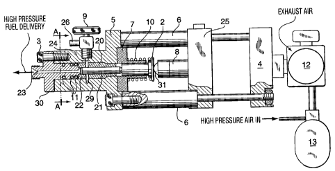
Figure 1 is a longitudinal cross section of modular fuel injection unit for
use in an
ignition quality tester in accordance with the invention; and
-1-


CA 02191509 2004-10-14
Figure 2 is a cross section of the injection unit taken along the lines A-A in
Figure
1.
The modular injection unit shown in Figure 1 injects fuel into a test bombe
(not
shown) providing a constant volume combustion chamber where ignition takes
place.
The injection unit comprises a pump block 5 with a cylindrical bore 22
containing
a barrel 20 and plunger 21. The plunger 21 faces a narrow channel 23 in barrel
clamp 3,
which communicates with the test bombe and extends into the bore 22. Seals 11
prevent
leakage past the body of the barrel clamp.
A cam follower 2, slidable in follower guide 7 extending into the cylindrical
bore
22, is biased outwardly by spring 10 and is attached to the near end of the
plunger 21.
A bleed valve 9 communicates through channel 24 with the cylindrical bore to
bleed off excess fuel.
The pump body S is separated from actuator unit 25 by spacers 6 which ensure a
rigid coupling. The actuator includes an air cylinder 4 containing a piston
(not shown)
with a protruding piston rod 8.
Air is stored in container 13 at a pressure of 1?5 psi and periodically
released,
typically at the rate of five times per minute, by a signal from a controller
into air cylinder
4 by pilot-operated solenoid valve 12. This causes piston rod 8 to strike the
cam follower
2 with considerable force, driving home the plunger 21 and causing it to
inject fuel into
the bombe at a pressure in the region of I?5 psi.
On the return stroke, a limited and precise quantity of fuel is drawn from
supply
29 at 50 psi through the channel 28 on the lower side of the bore 22. Any
entrapped air is
bled from the pump unit by bleed valve 9.
When the fuel delivery is complete, the solenoid valve 12 is switched to
exhaust
air in cylinder 4 to atmosphere, and piston rod 8 and plunger I return under
the action of
spring 10 to the stand-by condition.
Two 110 VAC heaters 27 maintain a constant temperature in the pump block 5. A
thermocouple continually monitors the temperature of the pump block 5 and the
output is
used to control the heaters. The pump block 5 is normally heated to
35°C +/- 1°C.
-2-


CA 02191509 2004-10-14
The above-described unit is capable of delivering 0,10 g of fuel within +/-
0.5%
per cycle and can run without maintenance or adjustments for thousands of
cycles at five
cycles per minute. It can accurately inject fuels with cetane numbers from 15
to 100 and
viscosities of all available commercial fuels. The construction can be made
simple with a
minimum number of moving parts. Each unit can be modular so that it can be
bench
tested and calibrated for installation on original equipment or supplied as a
replacement
exchange unit for equipment in the field. Used units may be re-cycled by over-
haul and
recalibration.
The unit can be easily purged and bled when changing to fuels of differing
specifications.
-3-

Representative Drawing
A single figure which represents the drawing illustrating the invention.
Administrative Status

For a clearer understanding of the status of the application/patent presented on this page, the site Disclaimer , as well as the definitions for Patent , Administrative Status , Maintenance Fee  and Payment History  should be consulted.

Administrative Status

Title Date
Forecasted Issue Date 2005-10-11
(22) Filed 1996-11-28
(41) Open to Public Inspection 1998-05-28
Examination Requested 2001-09-28
(45) Issued 2005-10-11
Expired 2016-11-28

Abandonment History

There is no abandonment history.

Payment History

Fee Type Anniversary Year Due Date Amount Paid Paid Date
Application Fee $0.00 1996-11-28
Registration of a document - section 124 $100.00 1997-09-04
Maintenance Fee - Application - New Act 2 1998-11-30 $50.00 1998-11-18
Maintenance Fee - Application - New Act 3 1999-11-29 $50.00 1999-10-27
Maintenance Fee - Application - New Act 4 2000-11-28 $50.00 2000-11-23
Request for Examination $200.00 2001-09-28
Maintenance Fee - Application - New Act 5 2001-11-28 $75.00 2001-11-22
Maintenance Fee - Application - New Act 6 2002-11-28 $75.00 2002-11-15
Maintenance Fee - Application - New Act 7 2003-11-28 $75.00 2003-11-12
Maintenance Fee - Application - New Act 8 2004-11-29 $100.00 2004-11-26
Final Fee $150.00 2005-07-28
Maintenance Fee - Patent - New Act 9 2005-11-28 $100.00 2005-11-28
Maintenance Fee - Patent - New Act 10 2006-11-28 $125.00 2006-11-24
Maintenance Fee - Patent - New Act 11 2007-11-28 $125.00 2007-11-26
Maintenance Fee - Patent - New Act 12 2008-11-28 $125.00 2008-11-25
Maintenance Fee - Patent - New Act 13 2009-11-30 $125.00 2009-11-23
Maintenance Fee - Patent - New Act 14 2010-11-29 $125.00 2010-11-10
Maintenance Fee - Patent - New Act 15 2011-11-28 $225.00 2011-11-01
Maintenance Fee - Patent - New Act 16 2012-11-28 $225.00 2012-09-21
Maintenance Fee - Patent - New Act 17 2013-11-28 $225.00 2013-10-02
Maintenance Fee - Patent - New Act 18 2014-11-28 $225.00 2014-10-29
Maintenance Fee - Patent - New Act 19 2015-11-30 $225.00 2015-11-06
Owners on Record

Note: Records showing the ownership history in alphabetical order.

Current Owners on Record
ADVANCED ENGINE TECHNOLOGY LTD.
Past Owners on Record
HOLE, NORMAN J.
ROTHERAM, GEOFFREY A.
WEBSTER, GARY D.
Past Owners that do not appear in the "Owners on Record" listing will appear in other documentation within the application.
Documents

To view selected files, please enter reCAPTCHA code :


To view images, click a link in the Document Description column. To download the documents, select one or more checkboxes in the first column and then click the "Download Selected in PDF format (Zip Archive)" or the "Download Selected as Single PDF" button.

List of published and non-published patent-specific documents on the CPD .

If you have any difficulty accessing content, you can call the Client Service Centre at 1-866-997-1936 or send them an e-mail at CIPO Client Service Centre.


Document
Description 
Date
(yyyy-mm-dd) 
Number of pages   Size of Image (KB) 
Representative Drawing 1998-06-04 1 31
Cover Page 1997-04-01 1 11
Abstract 1997-04-01 1 8
Description 1997-04-01 3 79
Claims 1997-04-01 1 23
Cover Page 1998-06-04 1 59
Drawings 1997-04-01 2 49
Drawings 2004-10-14 2 47
Claims 2004-10-14 2 48
Description 2004-10-14 3 112
Representative Drawing 2005-03-17 1 19
Cover Page 2005-09-15 1 43
Abstract 2005-10-10 1 8
Assignment 1996-11-28 7 220
Prosecution-Amendment 2001-09-28 1 32
Correspondence 1997-01-07 1 40
Correspondence 2002-11-08 1 35
Prosecution-Amendment 2004-04-14 3 98
Prosecution-Amendment 2004-10-14 9 273
Correspondence 2004-11-26 1 36
Correspondence 2005-07-28 2 59
Correspondence 2007-11-26 1 32
Correspondence 2008-11-25 1 41
Correspondence 2009-11-23 1 32
Correspondence 2010-11-10 1 27