Note: Descriptions are shown in the official language in which they were submitted.
16456 CA
2l9l528
ROCl~ER SWITCH
The invention relates to a rocker ~witch, and more
particularly, to a rocker switch which activates a dome
5 switch.
Membrane ~witche~ are well known as a method to
activate switche~3 in consumer products. These switches
are typically either of :the electr(~m~ h~nl cal type of
~witch or the elastomeric membrane ~witch. U.S. patent
5,147,990 ~hows the use of a ~lide switch to activate
the ela~tomeric membrane ~witch. A slide switch
activates a cantilevered beam which i8 pressed onto an
elastomeric keypad. A conductive pad on the elastomeric
keypad is then pushed into contact with traces on the
l5 keypad.
~ J.S. patent No. 4,4011864 ~how~ a rocker ~witch
that i~ used to activate electromechanical switches
mounted on a substrate. The switch has a return member
which returns the switch to a neutral position so that
~0 it i8 ready for the next switching operation.
When a rocker qwitch i9 u~ed on a piece of outdoor
e~uipment, such as a ~nowmobile, it is nece~sary to
build a rocker bwitch t~at provldes greater tactile
feel When the e~luipment is in opera~ion, ~t is
25 necessary to provide a switch in which the operator can
f eel that he ha~ activated the ~witch . Thi3 f eel mu~t
be detectable through equipment vibration and al~o
- through layers of clothing. It is also necessary to
protect the underlying switches from damage due to
30 excesf~ f orce and f rom damage due to ice build up .
The invention comprises a rocker 8witch which
includes a rocker member having an actuating ~urface, a
bottom surface, and a pivot member. A circuit board has
a dome switch mounted thereon. A bracket is secured to
35 the circuit board having a pivot guide to receive the
pivot member. A elastomeric member i8 received between
16456 CA 2 1 9 1 5 2 8
the bottom surface of the rocker member and the dome
switch. Actuation of the rocker member presses the
bottom ~urface of the rocker member against the
elastomeric member which presses again~t the dome switch
thereby activating the switch.
The invention further comprises a rocker switch
which includes a switch member having an actuation
surface7 a working surface, and a plvot member. A
circuit board has a dome switch thereon. A bracket
lo member i5 secured to the circuit board and has a pivot
guide to position the switch member over the dome switch
while allowing rocking motion thereof. ~ elastomeric
member is received between the switch member and the
circuit board Actuation of the switch member presses
the working surface against the elastomeric member which
presses the dome switch thereby activating the switch.
The elastomeric member distributes the load across the
circuit board thereby protecting the dome switch f rom
high forces and preventing moisture from accumulating
between the circuit board and the switch member to
prevent ice damage to the circuit board and the dome
swi t ch .
Fmbodiments of the present invention will now be
described by way of example with reference to the
accompanying drawings, in which:
Figure 1 is an isometric view of the handlebar unit
of the present invention;
Figure 2 is an exploded view of the handlebar unit
showing the components of the rocker switch;
Figure ~ is a cross - sectional view showing the
assembled rocker switch;
Figure 4 is a top view of the assembled rocker
switch;
Figure 5 is a cross - sectional view of the rocker
switch taken along the line 5 - 5;
~ 16456 CA - 21 91 528
Figure 6 is a cross-sectiQnal view showing the
components of the dome switch; and
Figure 7 is an isometric view of the silicon pad.
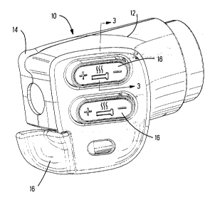
Pigure ~ ~shows a handlebar unit ~0 which can be
5 mounted onto the handlebar of a snowmobile or some other
piece of outdoor equipment. The unit 10 includes a top
housing 12 and a bottom housing 14. Along the top face
of ~che top housing 12 are several switch members 16
which are arranged 80 that the operator can easily
lO access the switch members while operating the vehicle,
without taking hi8 hands off the handlebar~. These
switches can be u8ed to operate lights, heat, horn, or
some other feature that an operator would desire to
switch on or of f during the operation of the vehicle .
Figure 2 is an exploded view of the unit 10 showing
the top housing 12, the bottom housing 14, and the
assembly therein. In this representative embodiment,
the= switch members 16 lnclude two rocker swltches 18 and
one lever 8witch 20. The rocker switches 18 are
20 received through holes 22 in the top housing 80 that
they are acceEsible from the outside to be activated by
the operator.
A printed circuit board 24 is received within the
bottom housing 14. The board 24 has a series of dome
~5 switches 2 6 mounted thereon over a series of electrical
traces on the board The dome 8witch is represented
without detail and will be ,o~l ~; n~cl in more detail with
regard to Fig. 6. The dome switches 24 are preferably
metal in order to provide better tactile feel, however,
30 they could also be plastic. A bracket 28 is secured to
the board 24 to provide a mount for the rocker switches
18 and the lever 8witch 20. A silicon pad 30 is
received over the bracket 28 and the switches 18, 20 are
mounted on top of the silicon pad 30. The preferred
35 embQdiment utilizes a silicon pad, however, the silicon -
pad could be some other elastomeric member that is
~ 16456 CA 21 91 528
capable of providing the appropriate propertie~ of
activating the dome swltch with the nece~ary tactile
feel and preventing moisture build up between the
elastomeric member and the dome ~witch. The
5 represelmtative embodiment shows two individual rocker
switches 18, however, the invention could also be used
with other numbers or aLLdlly~ ~ of rocker switche~.
The bracket i~3 designed as one piece such that it can
~ecure all three switches 1~3, 20 to the circuit board 24 .
lo The ~ilicon pad 30 is al~o de~igned a~ one piece to be
received under the rocker switche~, but it would be
possible to have the bracket 28 and the silicon pad 30
exi~t as individual pieces to accommodate the individual
switches 18, 20.
The ~witches 18 each have a top ~urface 32 which
are actuation surface~ to be engaged by the operator.
The ~witch 18 al~o has a bottom surface 34 which is u~ed
to activate the dome switch 26. A pivot pin 36 extends
from either ~ide of the ~witch 18 (only one of which i~
~hown in Fig. 2) along the bottom Rurface of the 8witch
18 .
The bracket has mounting holes 3 8 which are used to
~ecure to the board 24. The bracket 28 has seveTal
up~tanding projection~ having cradle reces~es 40 to
~5 receive the plvot pln 36 of the rocker ~witch. The
cradle rece~se~ 40 are U-~haped rece~es that will
recelve the plvot pln 36 while allowing the pivot pin to
rotate wit~in the recess 40. The bracket 28 has two
cradle rece~ses 40 for each ~3witch that will be mounted
thereon. - -
Figure 3 show~ the rocker ~witch 1~ a~embled to
the board 24 and the top hou~ing 12. The rocker switch
18 has two pivot pin~ 36 which extend from either ~ide
of the switch 18. The bracket 28 i~ mounted onto the
board 24. The pivot pins 36 are received into the
cradle recesses 40 of the bracket 28. The silicon pad 30
16456 CA
2191528
is received between the switch 18 and the bracket 28.
The top housing 12 ha8 a pro~ection 42 that extends from
the top housing along the hole 22 _ The pro~ ection 42 is
partially received into the cradle recess 40 and engage~
the top portion of the pivot pins 36 thereby securing
the switch 18 in place, but 8till allowing the switch to
be rocked f orward and back .
Figure 4 shows a top view of the assembly without
the top housing 12. The pivot pins 36 are received
within the cradle recess 40 of the m~ nting bracket 28.
This view shows that the silicon pad 30 partially covers
the bracket 28, but the upstandiny projections which
contain the cradle recesses 40 are projected through a
hole in the sl~icon pad 30 50 that the pivot pins 36 can
be received within the cradle recesses 40. The silicon
pad 30 has mounting holes 44 which are aligned with the
n~ holes 38 of the bracket 80 that the mounting
member can be accessed through the silicon pad 30.
Figure 5 shows a cross 8ectional view of the switch
18 mounted onto the circuit board 24. The bracket 28 is
mounted on the board 24 and the silicon pad 30 is
received over the bracket. The rocker switch 30 is then
mounted thereon. The bottom surface 34 of the rocker
switch res ts on top of the sil icon pad 3 0 .
As can be seen in ~ig. 5 and Fig. 7, the silicon
pad 30 has a ledge 50 which is essentially the same
shape as the bottom surface 34 of the rocker switch 18,
extends around the switch 18 and on which the bottom 34
of the rocker switch 18 rest8. An inner lip 52 extends
upwardly from the ledge 50 and is received on the inside
of the rDcker switch. The inner lip 52 serves to keep
the switch 18 and the pad 30 aligned with each other.
l~elow the ledge 50, along the bottom surface of the pad
30, is a recess 54 which has an outer flange 56
extending outwardly f rom the recess . The portion of the
silicon pad which is received under the rocker 8witch 18
16456 C~
2l9i528
has a ledge 58 which is received over the bracket 28.
The silicon pad 30 i9 designed to minimize the amount of
moi8ture that can accumulate between the pad and the
dome switch 26. Even if moisture accumulates under the
rocker switch 18, the silicon pad prevents most of the
moisture from mlgrating to below the silicon pad 30.
Figure 6 shows the dome switch in more detail The
dome switch 26 is mounted onto the board 24. If the
dome switch is plastic, it is necessary to have a
~-nn~ t; ve pad mounted thereon, if lt is metal, the
conductive pad is unnece8sary. The board 24 is covered
by a membrane 66 which protects the dome switch and the
board f rom molsture . When the dome switch is depressed,
it engages traces 64 on the circuit board, thereby
activating the appropriate switch. A layer of
dielectric material 60 protects the traces 64 and also
provides a recess in which the dome switch can occupy.
The operation of the rocker switch is described
with referer,ce to Fig. ~. The top surface 32 of the
switch 18 is depressed by the operator. The bottom
surface 34 of the switch 18 thereby depresses the
silicon pad 30. The silicon pad 30 is depressed around
the recess 54 thereby flattening the recess and pushing
the flange 56 outwardly. The pressure from the silicon
pad 30 then depresses the dome 8witch 26 which engages
the traces 64 on the board 24 thereby performing the
switching operation.
The use of the silicon pad 30 between the dome
switch 26 and the rocker switch 18 provides greater
travel of the switch 80 that the operator can feel that
the switch has been operated. Further, the use of a
metal or plastic dome switch provides for greater
tactile feel for the operator.
The silicon pad prevents ice build-up on top of the
dome switch 26 and the circuit board 24. In a
snowmobile, it is not necessary to completely keep
~ 16456 CA 2191528
moisture out of the unlt. ~oweverr the build up of ice
on top of the dome switch would necessitate breaking
that ice each time the switch is depressed. Because the
silicon pad 30 is firmly secured ayainst the circuit
5 board 24, no moisture will ~rcllmlll~te between the
silicon pad 30 and dome switch 26. E~ven if moisture
accumulates under the rocker switch 18, it will not
migrate below the silicon pad because it is completely
sealed below the rocker switch 18.
One further advantage to the present invention is
that the silicon pad distributes the forces more evenly
thereby preventing damage to the dome switches 18.
The rocker switch of the present invention and many
of its attendant advantages w$11 be understood from the
15 f oregoing description . It is apparent that various
chanyes may be made in the form, construction, and
aLLdllyl ~ parts thereof without departing from the
spirit or scope of the inventi~, or sacrificing all of
lts material advantages.