Note: Descriptions are shown in the official language in which they were submitted.
2 1 9 l G ~ 8
20187
APPARAlUS ~OR SPR~ADING CHIPS, ~;~ r.y ~l~)NGA~r~D C~IPS IN 2'~R
Pf~ODrJCq'Io~ OF OR~ ~CHIP ~OARD
SPF~CTFICATION
~LD OP T~ INV~N~ION
My present invention relates to an apparatu~ for
spreading chips, e~p~cially elongated chipQ, ln the production o~
oriented-chip board and like boards fabricated from wood
material. More partlcularly, the invention r~lates to the
orlentation of ~uch chip~.
~ qR~UND OF T~E ~NVBN~ION
~n the production of chip board and e~pecially so-
call~d OSB board, i.e. oriented ~trand board, the OSB strands
generally have a consid~rable length, width and thic~ne~.
To fabricate ~uch boards in a proces~ for making chip
board, a prellminary ~tep i8 the spre~ding of the chips,
especially elongated or longitudinally-extending chips, upon a
recei~ing surface on whlch the layer o~ chips can be subjected to
compre~sion and heating ~o consolidate the chlps of the layer
into the pre~sed board.
The ~ood chip~ may ~e combined with a binder,
especlally a heat-activatable ~inder, and the layer may be
~ub~ected to a prepre~sing or inltially pres~ing ~tage and to one
219161~
Z0187
or more ~ubseguent pre~s1ng ~tage~ or a final prea~lng stage and
any of the preYsing stages may b~ accompanied by hea~ing. In
general, there~ore, a process involving hot pres lng ~ carried
ou~ .
Since the str~ngth of the resulting strand depend~ upon
the orientation of the chip~, the spreadlng stage involve~
pa~sing the ca~cade of chip~ through an orlenting ~ystem which
may comprise a multiplicity of vertical wall-~orm~ng elements
which can be fixed and can cooperatQ with orienting elements, the
lo wall-forming element~ defining shaft-llke pa~sage botween th~m
and the or~entlng elements having a drive enabling a periodlc
movement to be applied to the orientlng elements,
The chips them~elves can have ~lgn~ficant dimenslonQ
and may be bar-~haped elementq, for example, wlth a length of loO
to 350 mm, width~ of 5 to 60 mm and thickn~ses of 1.5 to 6 mm
(~ee German patent documents DE 195 30 211.9 Al and DE 195 30
212.5). The chip board which ls fabricated may have
sub~tantially greater thlckne~se~ and can be cut up to ~orm beams
and the like. It wlll be self-under~tood th~t an optimum
orientation o~ the chip~, espec~ally -~uch ~zable elongated
chips, i~ de~irable and contributing to such orientatlon i~ the
width of the ~haft-like columns between the wall elements
traverced by th~ chip~ and the d~men~ions of the chlps on the one
hand and the nature of the movement imparted to the or~enting
elements on the other hand. In the past the mo~ement has
~191bl~
20187
con6isted of bidirectional movement with a back and forth
mov~m~nt along a line for each orienting ~lement.
Improvement in the degree of orientatlon ha~ been found
to b~ neces~ary in order to provide compact ~igh ~trength beams
or 8tr~nds by the chip-orienting p~oce6~.
In one app~ratus as de6cribed ln German patent document
DE 17 03 832, the orienting elements have th~ linear back and
forth movement de~cribed above w~th succes~ive orienting element~
being moved counterphasally, i.e. in equal but oppo~ite
dir~ctlons. N~ second component of the movement i8 applied. The
orienting elements themsQlves are bar-6haped member~ ln the form
o~ rods or channel~ with short ~hanks. The deg~ee o~ orientation
which result~ from this apparatu~ is ~at~sfactory only in some
cases and turn~ out to be un~at~s~actory when the sha~t-~orming
passages betwe~n the ~all element~ ar~ relativQly wlde as i9
necessary to accommodate high t~roughputs of th~ c~ip material.
In the pa~t, there~o~e, such apparatu~ has not be~n u3ed
8ucce88~ully for high throughput-~.
When high throughputs of the chips was required, the
~preader generally compri~ed rotating tooth circular wheel~
(German patent document DE 11 74 058) and elliptical or like
disks ~German patent document D~ 37 06 272 Al). The high
throughput~ obtainable with these latter sy6tem~, however, i8 at
the expense of a high degree of orientation.
2)9i~18
20187
O~J~CT8 OP THF INV~N~I0~
lt is, thorQfore, the principal object of the pressnt
invention to provide an appara~u~ of th~ type first de6crlbed
which ls no improved that hlgher throughput~ can be obtained at
the sams time as thor~ ia an improvement in the degree of
orientation.
Another ob~ect of thi~ inventlon ls to provide a
spreader for elongated chips, especially wood chips for the
fabrication of chip board, whereby drawbacks ln earlier orient$ng
and chip-spreading system~ can be obviated.
8UMMARY OP TH~ INV~N~0~
T~ese ob; eCtB a~e attained, in accordance wlth the
invention ~y applylng to the orienting ~lement~ a movement which
include3 a displac JflL component in the dlrectlon of elongation
o~ the element~, i.e. in the horizontal direction and along the
wall element~ and orienting element~ and, in addition, a vertical
movement component which i~ perpendicular to the longitudinal
directlon. According to thQ ln~entlon, moreo~er, the orienting
elements are inverted U-~haped members whose U s~ank~ are of a
length at least equal to t~Q vertical movement component, i.e.
the component of movement in the direction transver3e to the
longitud~nal direction.
FurthermorQ, the shaft-forming wall elements are ~o
dispo~ed that they extend into the orienting element, l.e.
2 5 between the shank~ thereof.
21916~8
20187
More particularly, an apparatus for spreading chips in
con~unction wlth the production of chlp board and ~specially
elongated chips of wood can compri8e:
a multiplicity of mutually p~rallQl, horizontally
~paced vQrtical elongated sha~t-~orming wall elementQ between
which chip~ for forming a chip board can cascade toward a
receiving sur~ace;
a respective elongated orienting el~ment for Qach of
tho wall element~, each of the orienting element~ being of
lo ln~e~t~d-U ~ection w~th platQ-shaped shanks flanking the
respectlve wall element and ~ach wall element extending into the
respecti~e lnverted-U be~ween the shan~s t~ereof;
a drlve ~or periodically dlsplacing the orienting
element-~ with a vertical component o~ displacement and a
longitudinal component of di~placement perpendicular to the
vertical component of displacement and ln a directlon of
elongation of t~e wall and orienting element~, the shanks having
lengths at lea~t eq~al to the vertical dlsplacements of ~e
orienting elements.
~he drlve for periodically displac~ng the o~i~nting
element~ with th~ two components can readlly be a crank drive.
It has been found to be advan~ag~ous to provide mean~
for adju~ting the di~placement of the orient~ng elements, i.e.
the amplltude~ of the a~orementioned co~pon~nts which ad~u~tment
serves to optlmlze thc degree of orientation ~or scattering of
chip~ o~ a predetermined lenqth.
-- 5 --
21916I~
20187
Indeed it has ~l~o been found to be advantageou~ to
provide the orienting elements and the respectiv~ wall elements
in stages one above another, i.e. in a ~tacked relation~hip but
80 that the spacing between the elements diminishes downwardly
S from ~tage to stage a~ t~aver~ed by the cascade of chip3.
The apparatus of the invention allows an extremely high
throughput of chips without any negative effects as far a~
orientation of the chips i~ concerned. In other words ~he
apparatus achieves a high degree o~ orientation while
lo nevertheless allowing a high throughput.
JRIEP DE~CRIPTIO~ OF THE DRA~N~
The above and other object~, ~eatures, and advantagec
will become more readily apparent from the following de~cription,
reference being made to the accompanylng drawlng ln which:
FIG. 1 i~ a diagrammatlc vertical section of an
apparatus for orlenting wood chips taken in a plane perpendicular
to the longit~dinal dimension in which the wall elements and the
orienting elements extend;
~ IG. 2 is a vlQw taken along the line II - II of FIG.
1:
FIG. 3 is a perspective view diagra~matically
illustrating a drive for the orienting elements;
FIG. 4 i~ a fragmentary ~levational view illu~trating
how the ~troke of the crank drivQ is adjustable; and
2191~l~
20187
FIG. S $~ a block diagram illustratlng the production
of chip board utilizang the orientation apparatu6 of the
invention.
~P~C~FIC ICP~TION
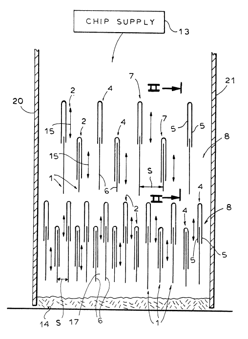
- S R~ferring flrst to FIG. 5, an initial stage in the
production o~ ch~p board i5 the mat formation and orientation
stage 10 which is followed by one or more hot pre6s~ng stages 11
and any trimming and cutting ~tages 12 which ~ay bc required. As
a part of the mat formation and orientatlon stage, the chips,
wh~ch are dellvered by a chip supply 13, i.e. a hopper and
metering ~ystem, can be subjected to orientation a~ they are
~cattered on a receiving 6urface 14 which can be a belt or tray
carrying the mat to and through the pressing stage or ~tages and
~eparated from the pre6~ed board be~ore it enter~ the trimm~ng
stage. The chip~ can be elongated splinter~ or particles of wood
when the system is used for the production o~ chip-oriented chip
board and like wood particle board~.
For the orientation purposes, a multiplicity of wall
elements or plates 1 are provided and these wall elements are
transversely spaced apart and extend longitudinally in a
direction perpend$cular to the plane of the paper in FIG. 1.
Bach ~uch wall element 1 is a6~0ciated wlth a slm$1arly elongated
orientlng element 2, the orienting elements being connectQd to a
drive 3 (FIG. 3) impartlng a periodic movement to the orienting
elements. One of the components of moYement ls in the verti~al
~1916~
2 0187
dlrcctlon a~ repre~ented by the arrow~ 15 ln FIG. 1 whlle the
other i~ a baclc and forth movement perpQndicular to the plane of
the paper, i.e. in the dlrection ~ repreQented in FIG. 2, the
arrows lS rcpre~ent the displacement component b in FIG. 2. A
composite o~ the two perlodlc movsments wlth component~ a and b
is a circular movement as represented by the arrow 16 in FIG. 2.
The orienting e1ements 2 them~elvec are lnverted U-
~ection members 4 who~e shanks 5 are at least of a l~ngth egual
to ~he displacement component b. Each two walls 1 act as wall~ 6
of a ~ha~t 17 through which the chips ca~cad~ downwardly and
these walls engage ln the lnverted U members 4. Each combination
of orienting elements 2 with the shaft-forming wall ~lement~ 1
de~ine clo~ed shaft walls 7.
A6 can be ~een from FIG. 3, the drlve 3 i~ a crank
lS drive which can be driven by a motor 18. As can be ~een from
F~G. 4, the amplitude or throw of the crank drive can be varied
by the rotation of sleeves 19 whlch threadedly engage oppositely
threaded rod portlon~ of the crank so that rotatlon of each
sleeve 19 in one direction will reduce the throw T of the
eccentric while rotation of the sleeve in t~e opposite direction
will increa~e the throw o~ the eccentric and hang the amplitude
of the movements of the orlenting element 2 ln the d~rection of
the two component~.
From FIG. 1 it wlll be apparent that each ~et of wall
element~ 1 and the re~pectlve orienting element~ 2 lie at a
re3pective le~el in ~he shafts between the walls 20 and 21 and
- 8 -
219l618
20187
the level~ have di~ferent ~pacings S of the wall elements l from
one another, the lower level having the ~mallQr spacing. With
this apparatu~, the wood chips, whlch can be comparatively long
~plinter~, are readily aligned in the longitudinal direction,
S i.e. with their chip axes parallel to ths wall element~ 1 and
~ubstantially horizontally to en~ure e~peclally high strength of
the chip board. ~he alignment is a~sured even with very high
throughputs of the chip material.