Note: Descriptions are shown in the official language in which they were submitted.
WO 95/33938 PCTIUS95107159
BFiIF'T CONTROL MECHANISM TO '.
otarrrtnr.Ly SgIFT AN AUTOMATIC TRANSMISSION
The present invention relates
generally to shift control mechanisms for
transmissions and, more particularly, to a shift
control mechanism to manually shift an automatic
transmission.
Automotive vehicles require a power
train to transmit the force of an engine to
wheels of the vehicle. The power"traia's main
component is typically referred to as the
"tranemissioa". Engiag torque sad speed are
converted in the transmission is accordance with
the tractive-power demand of the vehicle.
Transmissions are generally referred to as
manually actuated or automatic transmissions.
Manual transmissions generally include
mechanical mechanisms for coupling rotating
gears to produce different ratio outputs to
drive the wheels. Automatic transmissions are
designed to take automatic control of the
frictional unite, gear ratio selection and gear
shifting.
Recently, there has been a demand to
provide an automatic transmission that may be
manually shifted in addition to normal automatic
transmission operation. Such shifting is
SUBSTITUTE SHEET (RULE 26)
WO 95f33938 PCT/US95107159
- 2 -
typically provided by a shift control mechanism.
An a}sample of such a shift control mechanism is
disclosed in LT. S. Patent No. 4,905,530 to Stehle
et al. This patented shift control mechanism
for an automatic transmission includes a
selector lever,to be operated manually. The
selector lever,is displaced is a first shifting
lane for selecting different transmission speeds
during normal operation and transversely is a
second shifting lace to manually engage the
desired forward speed. However, there is a need
~.
is the art to provide a new and improved shift
control mechanism.
It is, therefore, one object of the
present 3avention to provide an improved shift
control mechanism far as automatic transmission.
It is another object of the present
invention to provide an improved shift control
mechanism to manually shift as automatic
r
transmission. r
To achieve the foregoing objects, the
present invention is a shift control mechanism
for an automatic trassmisaioa including a
housing.having a shift control pattern with a
longitudinal portion defining a plurality of
aut~atic transmission operating settings and a
transverse portion at one end of the
longitudinal portion defining a plurality of
manual transmission operating settings. The
shift control mechanism also includes a shift
lever mesas being manually moved along the shift
control patters for selecting the automatic
transmission operating settings and for
selecting the manual transmission operating
settings. The shift control mechasiam further
includes switch means actuated by moving the
shift lever means is a first direction in the
SU85TITUTE SF1E~~' (RULE 26)
219140
WO 95/33938 PCTIUS95147159
3
transverse portion to send a signal to manually
upshift the automatic transmission and in a
second direction in the transverse portion
opposite the first direction to senø a aigr_ ' to
manually downshift the automatic traasmissi...=.
One advantage of the present invention
is that a shift control mechaafsm is provided
for as automatic transmission. Another
advantage of the present invention is that a
shift control mechanism is provided for manually
shifting an automatic transmission.
Other objects, features and advantages
of the present invention will be readily
appreciated as the same becomes better
understood after reading the subsequent
description takes in conjunction with the
accompanying drawings.
FIG. 1 is as elevational view of a
shift control mechanism, according to the
present invention, illustrated in~operational
relationship with vehicle structure.
FIG. 2 is an enlarged plan view of the
shift control mechanism of FIG. 1.
FIG. 3 is a fragmentary side
elevatioaal view of the shift control mechanism
of FIG. 1.
FIG. 4 is a sectional view taken along
lice 4-4 of FIG. 2 illustrating the shift
control mechanism in a first~operational
position.
FIG. 5 is a view similar to FIG. 4
illustrating the shift control mechanism is a
second operational position.
FIG. 6 is a partial play view of a
shift control pattern for the shift control
mechanism of FIG. 1.
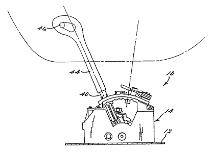
Referring to FIG. 1, a shift control
SUBSTITUTE SHEET (RULE 26)
WO 95133938 PCTILiS95/07I59
_ 4
mechanism 10, according to the present
invention, is,illustrated in operational
relationship with vehicle structure 12 such as a
vehicle floor of an automotive vehicle (not
shown). The shift control mechanism 10 is
operatively connected to each of a cylinder key
(sot shown) and an automatic transmission (sot
shown) via cables (not shown). The automatic
transmission may be of the type disclosed in
U.S. Patent No. 4,875,391 to Leising et al., the
disclosure of which is hereby incorporated by
reference. The connections of the shift control
mechanism 10 to the automatic transmission and
cylinder key are similar to that disclosed in
U.S. Patent No. 5,207,124 to Anderson et al.,
the disclosure of vrhich is hereby incorporated
by reference.
Referring to FIGS. 1 through 4, the
shift control mechanism i0 includes a housing,
generally indicated at 14. The housing 14 is
generally rectangular in shape and has a bottom
wall 16. The housing 14 also has a pair of side
wails 18 sad 20 spaced transversely and a pair
of end walls 22 and 24 spaced longitudinally and
extending upwardly generally perpendicular to
the bottom wall 16. The housing i4 further
includes a cover 26 having an arcuate-shaped
r
central portion 28 and generally planar flange
portions 30 secured to a top edge of the walls
18, 20, 22, 24 by suitable means such as screws
32. It should be appreciated that the walls 16,
18, 20, 22 and 24 may be integral and formed as
one-piece from a plastic material such as by
molding.
Referring to FIGS. 2 and 6, the
central portion 28 of the cover 26 includes a
shift control pattern foxed by an inverted and
SUBSTiTiITE SHEET (RULE 26)
~~~~~3~~
W0 95133938 PCTIUS95107159
- 5 _
generally T-shaped guide slot 34 extending
therethrough. The guide slot 34 has a
longitudinal portion 36 with predetermined
automatic,transmission operating gears or
settings such as Park (p), Reverse (R), Neutral
(N) and Drive (D) for selecting transmission
speeds to be automatically engaged in the
automatic transmission during normal automatic
transmission operation. The guide slot 34 has a
transverse portion 38 at one end of the
longitudinal portion 36 with predetermined ',
manual transmission operating settings such as
Manual (M), Upshift (+) and Downshift (-) to
select and manually shift or engage the desired
forward speed during manual operation of the
automatic transmission. It should be
appreciated that the M setting may be replaced
with the D setting sad that the automatic
transmission may be manually shifted by moving
transversely from the D setting tcs either the +
or - setting.
Referring to FIGS. 1 through 4, the
shift control mechanism 10 also includes a shift
lever 40 to shift the automatic transmission.
The shift iever,,40 extends through the guide
slot 34 in the cover 26 and is manually operated
or displaced through the Park (P), Reverse (R),
Neutral (N), Drive (D), Manual (M), Vpshift~(+)
and Downshift (-) settings. The shift lever 40
has a shift rod 42 slidably mounted therein.
The shift lever,40 also has a palm abutting knob
44 surrounding the shift lever 40 and a push
button 46 extending from the palm abutting knob
44 for a function as described in U.B. Patent
No. 5,207,124 to Anderson et al.
The shift control mechanism 10 further
includes a mounting assembly, generally
i
SUBSTITUTE SH~ET (RUL~ 2fi)
2~ 9~ ~~4~
' ~ WO 95/33938 PC'TIDS95107159
-s-
indicated at 48, for pivotally mounting the
shift Lever 40 within the housing 14. The
mounting assembly.48 includes a bracket 50
having an inverted and generally U-shape. The
bracket 50 has a generally horizontal base
portion 52. with a central opening 54 and leg
portions 56 generally perpendicular to and at
each end of the base portion 52. The base
portion 52 has a bushing 57 disposed in the
central opening 54. The leg portions 56 include
an opening 58 extending therethrough near a free
end thereof. The mounting assembly 48 also
includes a pivot pin 60 for pivotally mounting
the bracket 50 to the housing 14. The pivot pin
6fl is mounted between mounting brackets 62
formed oa the bottom wall 16 of the housing 14.
The pivot pin 60 extends through the openings 58
of the leg portions 56 sad a passageway 64 of
the mounting brackets 62. It should be
appreciated that the bracket 50 pi7rots or
rotates longitudinally about the pivot pin 60.
The mounting assembly 48 also includes
a connecting member 66 for pivotally connecting
the shift lever 40 to the pivot pin 60. The
connecting member 66 has a cavity 68 to form a
generally U-shaped cross-aectioa. The
connecting member 66 also has a pair of
transversely spaced and dowawardly extending
flanges 70 with openings 72 extending
therethrough. The pivot pin 60 extends through
the openings 72 is the flanges 70 to allow the
connecting member 66 to pivot or rotate
longitudinally about the pivot pin 60. The
mounting assembly 48 includes a cross-over pin
74 for pivotally connecting the shift lever 40
to the connecting member 66. The cross-over pin
74 extends through openings in the shift lever
SUBSTITUh SH~E? (RUL~ 26)
2191840
WO 95/33938 PCTYUS95107I59
_ 7 _
40 snd connecting member 66 to allow the shift
lever 40 to pivot or rotate transversely about
the cross-over pin 74. It should be appreciated
~ that the connecting member 56 allows
longitudinal pivotal movement of the shift lever
40 in the longitudinal portion 36 of the guide
' 'slot 34 and the cross-over pin 74 allows
transverse pivotal movement of the shift lever
40 is the transverse portion 38 of the guide
slot 34. It should also be appreciated that the
longitudinal portion 36 of the guide slot 34
prevents transverse pivotal movement of the
shift lever 40 and guides the shift lever 40
along a predetermined path.
The mounting assembly 48 may include a
tubular member,76 with a bottom seat 78 secured
to a left end of the bracket 50 by suitable
mesas such as vrelding. The mounting assembly
may also'include a detest member 80 slidabiy
mounted in the,, tubular member 76 sad urged
upwardly therefrom by a coil spring 87 mounted
between the bottom seat 78 and a flange 84
formed around the detest member 80. The detest
member 80 has an extended end 86 which is
rounded sad received in a plurality of rounded
indentations 88 are formed is the inner surface
of an edge portion of the central portion 28 of
the cover 26. A further explanation of the
structure and operation may be found in U.S.
Patent No. 5,207,124 to Anderson et al.
. The mounting assembly 48 further
includes a first guide member 90 having a
central opening 92 disposed about the shift
lever 40. The guide member 90 has a plurality
of steps 94 spaced axially and formed in an
outer periphery thereof for a function to be
described. The mounting assembly 48 includes a
- SUBSTITUTE SHEET (RULE 26)
~~ ~~ ~~~
WO 95133938 PC'TIUS95/07159
_ g _
second guide member 96 oa an interior surface of
the cover 26. ,,Preferably, the second guide
member 96 is integral with the cover 26. The
second guide member 96 has a cam prqfile or
cooperating surface 98. The steps 94 of the
guide member 90 form a generally point contact
with the cooperating surface 98 to move
therealong. The mounting assembly 48 also
includes a retainer bushing 100 disposed about
the shift lever 40 and a coil spring 102
disposed sbout,the shift lever 40 between the
first guide member 90 and the retainer bushing
10D. The coil,spring 102 urges the first guide
member 90 axially away from the retainer bushing
100. It should be appreciated that the retainer
bushing 100 is fixedly secured to the shift
lever 40 and the first guide member 90 is
slidable along the shift lever 40.
The shift control mechanism 10 also
includes a switch assembly, genera3iy indicated
at 104,-to send signals directly to a
transmission controller (not shown) for shifting
the automatic transmission. Such a transmission
controller is disclosed in V.B. Patent No.
4,875,391 to Leising et al. The switch assembly
104 iacludes,switches 106 disposed oa each
transverse aide,of the slot 36 in the cover 26.
The switches I06 are attached to the cover 26 by
suitable mesas. The switches 106 have a spring
3D loaded contact 108 which extends outwardly over
the + and - settings of the transverse portion
38. When the shift lever 40 contacts or
deflects one of,the contacts 108, the switch 106
sends a signal to the transmission controller.
The switches 106 are connected by connectors
(not shown) sad electrical wires (not shown) to
the transmission controller. It should be
SUBSTITUTE SHEET (RULE 26)
WO 95/33938 PCT/US95107159
- 9 -
appreciated that the transmission controller
executes a command to shift the automatic
transmission. '
The shift control mechanism 10 further
includes a return spring 110 for centering or
urging the shift lever 40 to the N setting. The
return spring IIO has a coil portion 112 secured
to the cover 26 by suitable mesas such as a
fastener 113. The return spring 110 also has a
.pair of fingers 114 extending longitudinally sad
spaced transversely by a spacer 116 extending ~. ,
upwardly from the cover 26. The shift lever 40
is disposed between the fingers 114.
Alternatively, the return spring 110 may be of
the toraioaal type and disposed about the cross-
over pin 74 or a pair of springs of the
compression type disposed oa opposed sides of
the shift lever 40 for centering or urging the
shift lever 40 to the N setting.
Ia operation, the shift'lever 40 is
moved longitudinally by an operator from the P
setting to either the R, N or D setting to allow
normal automatic operation of the aut~atic
transmission. i~Thea the shift lever 40 is is the
D setting, the operator may desire to manually
shift the automatic transmission. If so, the
shift lever 40iis moved longitudinally by the
operator from the D setting to the M setting to
allow manual shifting of the automatic
transmission. If a downshift is desired, the
operator moves transversely the shift lever 40
to the - setting to downshift the automatic
transmission. When this occurs, the shift lever
contacts sad deflects the contact 108 of the
35 switch 106 to send a signal to the transmission
controller Which then executes a command to
downshift the automatic transmission. As
SUBSTITUTE SHEET (RULE 26)
__ _ ______ __ ___ __
WO 95/33938
PCfIUS95/07I59
- IO -
illustrated in,FIG. 5, the first guide member 90
moves dowawardly against the spring 102 and one
of the fingers 114 of the return spring 110 is
deflected transversely. After the shift lever
40 is moved to the - setting, the operator
releases the shift lever 40. Nhen this occurs,
the finger 114,movea the shift lever 40
transversely to the M setting and, sa the coil
spring 102 urges the first guide member 90
upwardly, the steps 94 of the first guide member
90 slide along the cooperating surface 98 of ~ .
second guide member 96. It should be
appreciated that the operation is similar for
movement of the shift lever 40 from the M
setting to the f setting for an upshift of the
automatic transmission.
Accordingly, the shift control
mechanism 10 allows an operator to choose
complete automatic control of the~automatic
transmission by,leaviag the shift'lever 40 in
the longitudinal portion 36 of the guide slot 34
or can change gears manually by moving the shift
lever 40 in the transverse portion 38 of the
guide slot 34.
The present invention has been
described in an,illuatrative manner. It is to
be understood that the terminology which has
been used is intended to be in the nature of
words of description rather than of limitation.
Many modifications sad variations of
the present invention are possible in light of
the above teachi,ags. Therefore, within the
scope of the appended claims, the present
invention may be practiced other than as
specifically described.
SUBSTITUTE SHEET (RULE 26)