Note: Descriptions are shown in the official language in which they were submitted.
CA 02191866 2004-11-02
1
CUTTING INSERT WITH A THREADED CENTRAL APERTURE
The present invention relates to a cutting insert with an
entirely or partly threaded integral central hole.
The vast majority of the plurality of different cutting
inserts existing today on the market have a through central
hole. This hole is intended to accommodate a suitable locking
screw for fastening the insert in a holder. If the cutting
insert is intended for turning, the holder usually consists
of
a turning bar; if the cutting insert is intended for milling,
the holder is, e.g., a milling cutter body, a long edge milling
cutter or an end mill. The cutting insert may also be intended
for boring and then it may be fastened by a screw in a boring
shaft. The most common is that the cutting insert is an
indexable cutting insert, which means that when a cutting edge
has been worn out, the locking screw may be loosened and the
insert turned half a or a quarter of a revolution, whereby a
new cutting edge is placed or indexed into an operative
position. Cutting inserts including indexable cutting inserts
exist with innumerous different geometries, in order to give
a good chip breaking and chip control and a low effect
consumption. The inserts are mostly made of coated or uncoated
cemented carbide, but cutting inserts of different ceramic
materials also exist. They usually have a square, triangular,
rhombic, rectangular or hexagonal basic shape, but other basic
shapes also occur. However, they usually have one thing in
common, namely that they are all provided with a through
central hole in the geometrical central point . These holes
can
have different hole designs, but they all have in common that
the hole wall is substantially smooth. As mentioned, a threaded
screw is inserted into this smooth hole and is threaded into
a threaded hole in the holder per se, upon which the insert
rests, and is fastened onto this holder. This basic
configuration usually functions satisfactorily, but is
nevertheless marred by some drawbacks, which it would be
desirable to eliminate. For instance, the screw head must be
countersunk into the insert' s hole in order not to obstruct
the
WU 9SI335g0 ~ ~ (~, ~ j j ~ PCT1SE95JOOfiU3
2
chip flora, which brings about a further weakening of the
cutting insert, which is already relatively fragile. Further,
specifically because of this weakening of the insert's
r
strength, the central hole cannot be made with too a largo
diameter, which entails that the screw's diameter also becomes
relatively weak. Therefore, it sometimes occurs that the screw
is broken when tightening it uncarefully and/or too strongly.
Seen from anather aspect, the maximal allowed screw diameter
restricts the possible magnitude of the tightening strength.
Another disadvantage is that the requirement of
accessability to the screw head sometimes constitutes a
complicating and restricting factor when elaborating new
constructions, e.g., for extremely close pitch cutters. Another
case when good accessability is desirable is when a very large
number of cutting inserts are to be screw-fastened by a power-
driven screw tightener with a preset maximal torque. For
instance, at some bar peeling operations the number of cutting
inserts is very high and the accessability with such a screw
tightener is bad.
Thus, one object of the present invention is to
provide a cutting insert with a larger hale diameter in order
to make possible larger tightening forces.
Another object of the present invention is to impro~,re
the accessability when tightening the locking screw.
These and other objects have been achieved in a
surprisingly simple way by providing a cutting insert with a
wholly or partly threaded central hole in accordance with the
characterizing Bart of claim I.
For illustrative but non-limiting purposes, the
invention will now be further described with reference to the
appended drawings. These are herewith presented:
Figure 1 shows in the form of an exploded view the '
fastening of a cutting insert according to the present
invention, in a perspective view obliquely from below.
Figure 2 shows another embodiment of the fastening of
a cutting insert according to the present invention, in a
perspective view obliquely from above.
Figure 3 shows another embodiment for fastening the
WO 95/33590 PCTlSE95100603
~l~i~u6
3
cutting insert according to the present invention.
Figure 4 shows the cross-section A-A in figure 3.
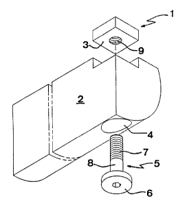
In figure 1 a cutting insert, inclusive an indexable
cuttin insert is
g , generally designated by 1, and a holder by
. 5 2. The cutting insert is made of one single piece. The geometry
of the cutting insert 1 is not essential for the present
invention, as long as the bottom support surface 3 partly or in
its entirety has sufficient planity to withstand the stress and
guarantee a stable cutting position.
The construction of holder 2 also is not an essential
feature for the present invention, wherefore its depicting in
the figures should be understood as purely principal. According
to th'e embodiment as shown in figure 1, the holder is provided
with a through-hole 4, which is intended to accomodate a
lacking screw 5. The head 6 of the locking screw is suitably
countersunk into the hole 4, this being shaped with a larger
diameter in its lower part. Suitably, the hole is smooth in its
entirety. However, the hole 4 may also be provided with a
threaded part corresponding to the screw's thread 7, which is
threaded past the thread of the hole and thereafter cannot fall
out of the hole 4 any longer. In this case, the screw's
unthreaded part 8 has to be of a somewhat smaller diameter than
the diameter of the thread 7, in order to rotate freely in the
thread of the hole.
The essential feature of the present invention is
that the central hole 9 of the cutting insert is threaded, in
order to be fastened by the thread 7 of the locking screw, the
thread of the insert being formed directly in the hard material
of which the insert consists. Since the production of such a
thread is not possible by conventional form pressing, the
insert is produced by an injection moulding technique, which is
previously known as such. This technique is a common production
technique in the plastic industry for the manufacturing of
different details. A paste consisting of or containing
thermoplastic or thermosetting polymers is heated to a suitable
temperature and is then pressed through a die into a mould of
desired geometry. In powder metallurgy injection moulding is
used for the production of relatively complex details of
WQ 95133590 ~ I ~ ~. ~ ~ ~ PCTlSE95tU06(>3
4
metallic powder, such as powder of cemented carbide. The
cemented carbide powder is then mixed with polymers. After
moulding, the polymer is driven off, wkxereafter tkm detail is
sintered in substantially the same way as carrespo:xding toal-
pressed details. The thread is obtained by providing the mould _
with a threaded tap in the middle, this tap being threaded out
after the moulding, or being burnt away after the sintering.
The type of threads as such is not essential for the
present invention. Thus, the central hale may be made with
different nut. threads which are well-known per se, such as for
instance a V-thread with a triangular basin profile ie.g.,
normal metric thread err so called M-thread?, different pipe
threads, trapezoid and square threads, and also so called round
threads. Further, the hole may be tapered, although a
cylindrical shape is most common. The advantage with a conical
thread is that the threads may be engaged and disengaged,
respectively, by a short turning, suitably less than two
revolutions.
Preferably, the central hole 9 is a through-hole, but
2a it may also Y>e a blind hole. In the latter case, the length of
the screw must of course be adapted thereto, in order to permit
a sufficient play between the screw's end and the bottom of the
hole.
Sf the accessability from above the cutting position
is good, a construction according to figure 2 may also be
chosen. In accordance with this, the cutting insert 1' is
fastened by a double-threaded differential screw. This screw
has two threaded portions 11 and 12, respectively, and an
unthreaded waist portion 13 between these two pork:iars. Sn a
way known p.,ea: se, these thread portions 11 and 12 are threaded
in opposite directions. For instance, if the portion 11 has a
left-hand thread, also the hole in the holder 2' is left-hand '
threaded, the thread portion 12 and the insert hole 9' being
right-hand threaded. The differential screw is rotated by
inserting a suitable tightening device inter the hole 14, which
suitably is hexagonal or of the so called, torx type. Also in
this case, the hole in the holder may be a through-hole, aisa
the other end of the differential screw being provided with a
W0 95133590 PC'ffSE95lOlIG03
S
suitable recess, for optional tightening either from above or
from underneath.
Still another embodiment for the fastening of a
cutting insert according to the invention is spawn in figures 3
and 4. According to these figures, a locking screw 15 is locked
in a rotatable state by a securing washer 16 with a threaded
envelope surface. The holder is provided with a blind hole 17,
which at least in its upper part is threaded for the thread-
fastening of securing washer 16. However, before the securing
washer is threaded into the hole 17, the screw is inserted
through the central hole of the securing washer, whereby the
screw is withheld in a rotatable state after the securing
washer having been fastened by the threads. The locking screw
is provided with a thread 18 which should be in the opposite
direction relative to the threading of the securing washer. The
end of the screw is formed with a rotation-symmetrical recess
19 for tightening the cutting insert (not shown), the recess 19
in a usual manner suitably being hexagonal or of the so called
torx type. If desirable, a hole of a smaller diameter than the
diameter of the blind hale 17 may open into the bottom of the
latter hole and concentrically with it, the head of locking
screw 15 being provided with a rotation-unsymmetrical hole in
substantially the same way as hole 19. In this way, the screw
may be rotated either from below or from above.
As may be conceived from the above description, still
another advantage of the present invention is based on the fact
that the locking screw can be withheld in the holder when
replacing a cutting insert, and when indexing a new cutting
edge for indexable cutting inserts. In this way, the sometimes
trying and time-consuming handling of small loose locking
screws is avoided, which may easily be dropped and/or be
difficult to set.