Note: Descriptions are shown in the official language in which they were submitted.
CA 02191981 2001-11-05
1
METHOD AND APPARATUS FOR CONTROL TNfi DlCe.wtavEn
DURING AUTOD~ATIC CAP DETECTtats
FIELD OF T8E INVENTION
The present invention generally relates to "capture"
of the heart, here defined as the presence of contractions
in the heart in direct response. to electrical stimulation
signals emanating from an artificial pacemaker
., ("pacemaker"). Also, the present.invention relates to
adjusting stimulation signal thresholds for pacemaker
energy efficiency.
HACRGROUND OF THE INVENTION
Generally speaking, a cardiac pacemaker is an
electrical device used to supplant some or all of an
abnormal heart's natural pacing function, by delivering
appropriately timed electrical stimulation signals designed
to cause the myocardium of the heart to contract or "beat".
Stimulation signals usually have well-defined amplitude and
pulse width characteristics which can be adjusted to meet
physiologic and device power conservation needs.
The strength (amplitude) and duration (pulse width) of
the stimulation signals must be of such magnitude that
capture is maintained, to prevent serious complications and
even death. Yet, it is desirable for these magnitudes not
to be higher than is needed for a.reasonable safety margin
for longer battery life. Chief among the problems is that
stimulation signal thresholds necessary for maintaining
capture often fluctuate in the short term, and gradually
change in the long term. It has been clinically observed
that the lowest threshold is observed immediately 'after
implantation of the pacemaker (the acute threshold).
Inflammation in the tissue around the tip of the
stimulation electrode requires greater energy to propagate
the stimulation signals, thereby driving the threshold up
sharply during the first two to six weeks to its highest
level. (the peak threshold) . Some .of the inflammation
reduces over the long-term, to lower the threshold below
the peak~level--the chronic threshold. However, the
chronic threshold does not reduce to the acute level, since
CA 02191981 2001-11-05
2
some permanent fibrous tissue, requiring greater energy
than non-fibrous tissue for signal propagation, remains
around the electrode tip. In the short-term, thresholds
may decrease with exercise, for example, and may increase
with various activities, including sleep.
Some prior art implantable pulse generators (IPOs)
which serve as cardiac pacemakers have an automatic capture
feature to maintain capture or restore capture after a
loss-of-capture episode, without the need for clinical or
patient, intervention. In addition, some of these IPC3s have
an automatic threshold-seeking feature, which, either after
capture restoration or periodically, seek the lowest "safe"
voltage level of the stimulation signal for energy
efficiency. That is, the voltage of the stimulation signal
is lowered to the newly detected threshold voltage plus a
safety margin, rather than using an unnecessarily high
stimulation signal voltage level.
During the search for thresholds, some prior
pacemakers deliver a backup pulse (as a safety measure)
2o after a primary pacing pulse in case the primary pacing
pulse fails to capture the patient's heart. The backup
pulse is delivered after the passage of a predefined
Vulnerable Period, as is well known in the art, to avoid
facilitating re-entrant tachycardia and fibrillation. As a
result, the aforementioned prior art pacemakers result in a
drop in pacing rate and long threshold searching times.
The patient may be aware of either the drop in pacing rate,
or alternatively an artificially elevated rate used to
compensate for the rate drop.
SVb~~ARY OF THE INVENTION
In view of the foregoing, the.first object of the
present invention is to provide a cardiac pacemaker having
an automatic capture feature in which capture is maintained
during automatic threshold-seeking.
The second object of the present invention is to
provide a cardiac pacemaker having an automatic capture
feature in which the pacing rate remains above bradycardic
levels during threshold searches.
CA 02191981 2001-11-05
66742-587
3
The third object of the present invention is to
provide a cardiac pacemaker having an automatic capture
feature in which data collected during operation of the
feature is used for diagnostic purposes.
The fourth object of the present invention is to
provide a cardiac pacemaker having an automatic capture
feature which leads to increased battery life.
The fifth object of the present invention is to
provide a cardiac pacemaker having an automatic capture
feature which prevents patient discomfort during its
operation.
The sixth object of the present invention is to
provide a cardiac pacemaker having an automatic capture
feature which has simple patient follow-up with feedback
during automatic determination of pacing thresholds.
The seventh object of the present invention is to
provide a cardiac pacemaker with the ability to
automatically generate a strength-duration curve based on
amplitude and pulse width searches.
The present invention may be summarized as a
pacemaker capable of automatically seeking stimulation
thresholds during successive automatic threshold seeking
stimulation cardiac cycles comprising: a pulse delivery and
generator means for being coupled to a patient's heart to
deliver primary and backup stimulation pulses; a capture
detector means coupled to receive indications of the capture
of said patient's heart in response to a detected capture,
generating a signal value related to the amount of time
between the delivery of said primary stimulation pulse and
said detected capture; said signal value setting minimum and
CA 02191981 2001-11-05
66742-587
4
maximum values of a capture detection window during a window
establishment period, and, following said window
establishment period, determining amplitude and pulse width
thresholds of primary pacing pulses based on whether there
is capture within said capture detection window; and wherein
said backup pacing pulses are delivered after said primary
pacing pulses during each automatic threshold seeking
stimulation cardiac cycle.
The details of the present invention will be
revealed in the following description, with reference to the
attached drawing.
BRIEF DESCRIPTION OF THE DRAWING
The various figures of the drawing are briefly
described as follows:
Figure 1 is a schematic block diagram of a multi-
sensor, rate-responsive, single chamber IPG capable of
subsuming the present invention;
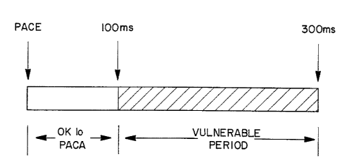
Figure 2 is a simple pacing timing diagram showing
the Vulnerable Period; and
Figure 3 is a typical strength-duration curve for
cardiac stimulation signals.
DETAILED DESCRIPTION OF THE INVENTION
PART I. DESCRIPTION OF PACEMAKER DEVICE
Figure 1 is a block circuit diagram illustrating a
multi-programmable, implantable, single-chamber, bradycardia
pacemaker 100 capable of carrying out the present invention.
This figure and related figures not presented in this
CA 02191981 2001-11-05
66742-587
letters patent are described in U.S. Patent No. 5,154,170,
issued October 13, 1992, and titled OPTIMIZATION FOR RATE
RESPONSIVE CARDIAC PACEMAKER, which patent may be referenced
by the reader for a broader understanding of this art.
5 Although the present invention is described in conjunction
with a microprocessor-based architecture, it will be
understood that it could be implemented in digital logic-
based, custom integrated circuit (IC) architecture, if
desired. It will also be understood that the present
invention may be implemented in dual-chamber pacemakers,
cardioverters, defibrillators and the like.
In the preferred embodiment of Figure l, pacemaker
100 includes two sensors, namely S1 and S2, each of which
provide a sensor output which varies as a function of a
measured parameter that relates to the metabolic
requirements of the patient. Since each sensor output can
be utilized by pacemaker 100 to control its pacing rate,
each sensor output is herein referred to as a rate-control
parameter (RCP). Examples of an RCP include, for example,
physical activity of the body, right ventricular blood
pressure and the change of right ventricular blood pressure
over time, venous blood temperature, venous blood oxygen
saturation, respiration rate, minute ventilation, and
various pre- and post-systolic time intervals measured by
impedance or pressure sensing within the right ventricle of
the heart.
In the preferred embodiment, the first sensor S1
comprises an activity sensor, such as a piezoelectric sensor
of the type disclosed in U.S. Patent No. 4,428,378 issued to
Anderson et al., entitled "Rate Adaptive Pacer", which is
held by the same assignee as the present invention. First
CA 02191981 2001-11-05
66742-587
6
sensor S1 thus measures a rate-control parameter related to
physiologic forces associated with body activity (RCPa~t),
and provides a first sensor output (Outputa~t) which is
proportional to the patient's activity. Also in the
preferred embodiment, second sensor SZ comprises a dynamic
pressure sensor, such as the type disclosed in U.S. Patent
No. 4,485,813 issued to Anderson et al., entitled
"Implantable Dynamic Pressure Transducer System", which is
held by the same assignee as the present invention. Second
sensor SZ thus measures a rate-control parameter related to
changes in fluid pressure in the heart associated with its
mechanical activity and contractility (RCPpress). and provides
a second sensor output (Outputpress) which is proportional to
the magnitude of the change in fluid pressure in the
patient's heart. In the preferred embodiment, second sensor
output S2 is processed to derive a peak positive time
derivative of the fluid pressure applied to the pressure
sensor SZ within the right ventricle of the patient's heart
(1.e., dP/dtmax)
Pacemaker 100 is schematically shown electrically
coupled via a pacing lead 102 to a patient's heart 104.
Lead 102 includes an intracardiac electrode 106 and second
sensor S2 which are located near the distal end of lead 102
and positioned within the right ventricle (RV) of the
patient's heart. Lead 102 can carry either unipolar or
bipolar electrodes as is well known in the art. In the
preferred embodiment, the lead 102 which couples pacemaker
100 to the ventricular endocardium can comprise a steroid-
tipped, unipolar lead with an integral pressure transducer
of the type described above. Electrode 106 is coupled via
suitable lead conductor 102a through input filter capacitor
108 to node 110 and to the input terminals of an
CA 02191981 2001-11-05
66742-587
7
Input/output Circuit shown at block 112. Output from first
sensor S1 is coupled to Input/output Circuit 112. Output
from second sensor SZ is also coupled to Input/output Circuit
112 via suitable lead conductor 102b.
Input/output Circuit 112 contains the operating
input and output analog circuits for digital controlling and
timing circuits necessary for the detection of electrical
signals derived from the heart, such as the cardiac
electrogram, output from the first sensor output S1, and
output from the second sensor output S2, as well as for the
application of stimulating pulses to the heart to control
its rate as a function thereof under the control of
software-implemented algorithms in a Microcomputer Circuit
shown at 114.
Microcomputer Circuit 114 comprises an On-Board
Circuit 116 and an Off-Board Circuit 118. On-Board Circuit
116 includes a microprocessor 120, a system clock 122, and
on-board RAM 124 and ROM 126. Off-Board Circuit 118
includes an off-board RAM/ROM Unit 128. Microcomputer
Circuit 114 is coupled by Data Communication Bus 130 to a
Digital Controller/Timer Circuit shown at 132.
Microcomputer Circuit 114 may be fabricated of custom IC
devices augmented by standard RAM/ROM components.
It will be understood by those skilled in the art
that the electrical components represented in Figure 1 are
powered by an appropriate implantable-grade battery power
source (not shown).
An antenna 134 is connected to Input/output
Circuit 112 for purposes of uplink/downlink telemetry
through a radio frequency (RF) Transmitter/Receiver Circuit
CA 02191981 2001-11-05
66742-587
8
(RF TX/RX) shown at 136. Telemetering both analog and
digital data between antenna 134 and an external device,
such as an external programmer (not shown), is accomplished
in the preferred embodiment by means of all data first being
digitally encoded and then pulse position modulated on a
damped RF carrier, as substantially described in U.S. Patent
No. 5,127,404, issued on July 7, 1992, entitled "Telemetry
Format for Implantable Medical Device", which is held by the
same assignee as the present invention. A reed switch 153
is connected to Input/output Circuit 112 to enable patient
follow-up via disabling the sense amplifier 146 and enabling
telemetry and programming functions, as is known in the art.
A Crystal Oscillator Circuit 138 typically a
32,768 Hz crystal-controlled oscillator, provides main
timing clock signals to Digital Controller/Timer Circuit
132. A Vref/Bias Circuit 140 generates a stable voltage
reference and bias currents for the analog circuits of
Input/output Circuit 112. An ADC/Multiplexer Circuit
(ADC/MUX) 142 digitizes analog signals and voltages to
provide telemetry and replacement time-indicating or end-of-
life function (EOL). A Power-on-Reset Circuit (POR) 144
functions to initialize the pacemaker 100 with programmed
values during power-up, and reset the program values to
default states upon the detection of a low battery condition
or transiently in the presence of certain undesirable
conditions such as unacceptably high EMI, for example.
The operating commands for controlling the timing
of the pacemaker depicted in Figure 1 are coupled by bus 130
to Digital Controller/Timer Circuit 132 wherein digital
timers set the overall escape interval of the pacemaker, as
well as various refractory, blanking and other timing
CA 02191981 2001-11-05
66742-587
9
windows for controlling the operation of the peripheral
components within Input/output Circuit 132.
Digital Controller/Timer Circuit 132 is coupled to
a sense amplifier (SENSE) 146 and an electrogram (EGM)
amplifier 148 for receiving amplified and processed signals
picked up from electrode 106 through lead conductor 102a and
capacitor 106 representative of the electrical activity of
the patient's heart 104. SENSE amplifier 146 produces a
sense event signal for re-setting the escape interval timer
within Circuit 132. The electrogram signal developed by EGM
amplifier 148 is used in those occasions when the implanted
device is being interrogated by the external
programmer/transceiver (not shown) in order to transmit by
uplink telemetry a representation of the analog electrogram
of the patient's electrical heart activity as described in
U.S. Patent No. 4,556,063, issued to Thompson et al.,
entitled "Telemetry System for a Medical Device", which is
held by the same assignee as the present invention and which
is mentioned for reference material it contains to assist
the reader in understanding this art. An output pulse
generator 150 provides the pacing stimulus to the patient's
heart 104 through an output capacitor 107 and lead 102 in
response to a paced trigger signal developed by Digital
Controller/Timer Circuit 132 each time the escape interval
times out, or an externally transmitted pacing command has
been received, or in response to other stored commands as is
well known in the pacing art.
66742-587
CA 02191981 2001-11-05
9a
Digital Controller/Timer Circuit 132 is coupled to
a processing/amplifying circuit (ACTIVITY) 152 for receiving
amplified and processed sensor output (Outputa~t) from first
sensor S1 and associated ACTIVITY circuitry which is
representative of activity. Digital Controller/Timer
Circuit 132 is coupled to a processing/amplifying circuit
(PRESSURE) 154 for receiving amplified and processed sensor
output (OutputPress) from second sensor SZ through lead
conductor 102b representative of changes in fluid pressure
in the patient's heart 104, for use in rate response
control, and other functions as desired.
In a preferred embodiment of the present
invention, pacemaker 100 is capable of operating in various
non-rate-responsive modes which include VVI, V00 and VVT, as
well as corresponding rate-responsive modes of VVIR, VOOR
and VVTR. Further, pacemaker 100 can be programmably
configured to operate such that it varies its rate only in
response to one selected sensor output, or in response to
both sensor outputs, if desired (i.e., utilizing either or
both of Outputa~t or Outputpress) .
PART II. DEFINITIONS
For purposes of describing this invention, a
definition of additional relevant terms follows:
Detection Window - A 170 mSec window beginning 30
mSec after a paced or sensed event used to detect the
presence of a pressure signal indicative of cardiac
contraction.
Loss-of-Capture (LOC) - Processing by pacemaker
100 detects the absence of a pressure signal in the
CA 02191981 2001-11-05
66742-587
9b
detection window after a paced event. This lack of
stimulated cardiac contraction is labeled Loss-of-Capture.
Lower Rate (LR) - A value supplied by the
clinician which establishes a lower boundary on the pacing
rate. If the sensors are disabled, or their sensor outputs
are not large enough to increase rate, the lower rate is the
stimulus rate. With rate response, the allowed
CA 02191981 2001-11-05
programmable values for LR range. from 40 pulses per minute
(ppm) to 100 ppm at 1 ppm intervals.
ric - The programmed (selected) output stimulus
parameter (pulse width or pulse amplitude) selected to be
5 modified in the response to Loss-of-Capture and during the
Recovery sequence.
Non-Metric - The non-selected output stimulus
parameter (pulse width or pulse amplitude). The non-metric
parameter is changed only at the maximum output stimulus
10 during response to Losa-of-Capture.
P~,x - Processing by pacemaker 100 determines the
maximum signal level in the pressure waveform from pressure
circuit 154 during a detection window.
P"~n - Processing by pacemaker 100 determines the
minimum signal level in the pressure waveform from pressure
circuit 154 during a detection window.
Pulse Pressure Average (PRESS.AVG) - Dynamic pressure
sensor S, is disposed in the right ventricle (RV) of the
patient's heart to sense fluid pressure therein (RCPp=",),
and to provide a sensor output (Outputps",) related to
changes in the fluid pressure associated with the heart's
mechanical activity and contractility. Processing by
pacemaker 100 of Outputpr", yields a peak pulse pressure
(PRESS.PK) which is proportional to the magnitude of such
RV pressure changes. Each sensed or paced RV event will
yield a peak pulse pressure signal. In the preferred
embodiment, a running average of the last 16 valid PRESS.PK
values are used to determine an average peak pulse pressure
value, referred to ae the "PRE89.AVG". Pacemaker 100 tests
for validity of each peak pulse pressure value on a sample-
by-sample basis, based upon the requirement that the
sampled PRESS.PK value must be equal to or greater than, 4
mm Hg. Values below this validity threshold are ignored.
Once determined, PRESS.AVG is used to detect capture on a
cycle-to-cycle basis. Recovery - Pacemaker 100
automatically attempts to adjust output stimulus parameters
1 hour after a Lose-of-Capture sequence. The metric
parameter is adjusted in small increments toward it's
programmed value.
CA 02191981 2001-11-05
11
Response to LOC - Pacemaker 100 automatically responds
to a LOC by increasing the output pulse width and/or
amplitude in a controlled response to enable rapid
restoration of cardiac stimulation.
Thr~ahold - A programmable threshold of continuously
averaged peak pulse pressure value based upon a percentage
of this stored peak value. The programmable range is 25-
75% in 12.5% steps.
Upper Rate (UR) - A value supplied by the clinician
l0 which limits the maximum stimulation rate when the rate
responsive modes for activity, pressure, or both combined,
are in effect, or when response to loss-of-capture pacing
is occurring such that the pacing rate generated by
pacemaker 100 does not become hemodynamically excessive.
The allowed programmable values range from 100 ppm to 175
ppm at 5 ppm intervals, provided.UR must also be at least
ppm greater than Lower Rate (LR) and Resting Rate
(REST. RATE).
PART III. SENSORS.
20 A brief description of measurement of the rate control
parameter for activity (RCP,~~) now follows. The activity
sensor S, sensor employed ie a piezoelectric crystal
transducer of the type described in the above-mentioned
'378 Anderson et al. patent, which is mounted to the
interior surface of the pacemaker can as disclosed therein.
Sensor S1 generates a sensor output (Output,at) due to~
deflection of the pacemaker can as a result of compression
waves within the body caused by physical movement of the
body. Processing by ACTIVITY circuit 152 is performed,
such that each event in which the amplitude of Output,~c
exceeds a programmed Activity Threshold (ACT.THRESH) is
then counted and retained in an Activity Count (ACT. COUNT)
of pacemaker 100. ACT.COUNT is used to calculate the
activity-based Target Rate (STR,~~) on a cycle-to-cycle
basis.
A brief description of measurement of the rate control
parameter for pressure (RCPDr",) now follows. The pressure
sensor S', sensor employed is a dynamic pressure sensor of
the type described in the above-mentioned '813 Anderson et
CA 02191981 2001-11-05
12
al. patent. Sensor. S, is disposed in the right ventricle
(RV) of the patient's heart to sense fluid pressure therein
(RCPp=~") , and to provide a s,enaor output (Outputpr...)
related to changes in the fluid pressure associated with
the heart's mechanical activity and contractility.
Processing by PRESSURE circuit 159 of outputp=." yields a
peak positive first time derivative thereof (dP/dt",X) which
is proportional to the magnitude of such RV pressure
changes. Each sensed or paced RV event will yield a peak
positive dP/dt",x signal, although a peak negative signal
may be used as an alternative. In the preferred
embodiment, the last a valid dP/dt,n,x values are used to.
determine an average dP/dt"" value, referred to as the
"Pressure (dP/dt) Average" or "dP/dt.AVG". Pacemaker 100
tests for validity of each dP/dt."x value on a sample-by-
sample basis, based upon the requirement that a sampled
dP/dt",x value must be within a predetermined range defined
by a dP/dtn,x value associated with the patient's Resting
Rate (REST. PRESS). In the preferred embodiment, this
validity range is defined as dP/dt"." values between 25~t to
900 of REST.PRESS. Values outside this validity range are
ignored. Once determined, PRESS.AVG is used to calculate
the pressure-based Sensor Target Rate (STRp=.") on a cycle-
to-cycle basis.
It will be understood, however, that the present
invention can be practiced with more than two sensors, or
with sensors of a type other than the ones above described.
In the preferred embodiment, however, various advantages
are obtained by the use of the particular sensors in the
specific combination stated above.
For example, an activity-based sensor provides a fast
and repeatable response to physical activity. Sensors of
this type have been exhaustively reported in clinical
literature, and their safety and efficacy are well-
documented. Additionally, such sensors offer the advantage
of being less affected by changes in a patient's health or
disease status, and thus provide more predictable behavior
over ti~rie. However, there are also theoretical and
practical limitations to the~behavior of activity sensors.
CA 02191981 2001-11-05
13
For example, they respond only to physical activity.
Therefore, patients undergoing other types of physiological
stresses which would normally evoke a heart rate response,
such as thermal stress associated with normal exposure to
wide variations in ambient temperature, or postural stress
associated with changing from lying down to an erect
position, will tend to obtain only very limited rate
adjustment and their adjustment to such stresses will thus
be leas than entirely adequate. Additionally, the time
course of rate recovery after an activity event tends to be
limited by the design constraints of the pacemaker system
which are not generally capable of providing a highly
physiologically-based recovery function.
Consequently, the preferred embodiment also
incorporates a dynamic pressure sensor for continuous
measurement of cardiac pressures on a beat-by-beat basis.
This sensor provides for more physiological responses than
activity alone, and helps to complement the rate response
provided by the activity sensor. The sensed physiologic
variable in this system comprises the rate of increase in
pressure within the right ventricle of the heart (i.e., a
peak positive dP/dt). This variable is related to the
vigor of contraction of the cardiac muscle, which in turn
is regulated by the autonomic nervous system. Thus, any
stress which elicits a response by the autonomic nervous
system in the patient (and would cause a heart rate
response in a normal individual), will also yield a heart
rate response in the patient by means of the pacemaker
system of the present invention. Additionally, the time
course of recovery of the cardiac pressure following
stresses follows the physiologic time course determined by
the status of the autonomic nervous system, such that the
present device will provide for pacing rate recovery which
is more physiological than that which can be provided by
activity sensors alone.
It can thus be appreciated that the particular sensor
combination described above yields significantly improved
rate response function for pacemaker 100.
CA 02191981 2001-11-05
66742-587
14
PART IV. AUTOMATIC CAPTURE AND THRESHOLD-SEEKING FEATURES.
Specific details of the auto-capture and
threshold-seeking features of the present invention follow
below. Of related interest are U.S. Patent No. 5,370,643
which issued on June 14, 1994 and U.S. Patent No. 5,447,525
which issued on September 5, 1995, which patents are also
assigned to the assignee of the present application which is
mentioned for reference material it contains to assist the
reader in understanding this art. Those U.S. patents
provide additional details about auto-capture and threshold-
seeking functions which may be modified to operate in
conjunction with the present invention.
Capture Verification
Physiological changes in the patient may alter the
thresholds from the initial programmed value or values, and
can lead to loss of capture, with inadequate amplitude or
pulse width. The pacemaker 100 is capable of detecting loss
of capture via a capture detector using the pressure sensor
SZ and evoked responses, for example, as is known in the art.
Thus, a "CAPTURE DETECT" message is produced when capture is
present, and a "NO CAPTURE DETECT" message is produced
during a loss-of-capture episode.
Either a CAPTURE DETECT message or a NO CAPTURE
DETECT message occurs in a predefined capture detect window
(CDW) following a pacing pulse during capture verification.
The duration of the CDW may be programmed to a suitable
value. A full-amplitude backup pulse is rapidly delivered
for safety purposes. The backup pulse occurs within 100 ms
in the preferred embodiment, which is before the Vulnerable
Period begins. Figure 2 is a timing diagram illustrating
CA 02191981 2001-11-05
66742-587
the Vulnerable Period and a safe backup pacing interval.
Note that in prior art pacemakers, the backup pulse would
not be delivered until at least 300 ms after the primary
pacing pulse.
5 The backup pacing pulse restarts the pacemaker
escape interval. The pacemaker 100 then methodically
changes the regular pacing pulses as described below, until
capture is achieved by the regular pacing pulses.
After each loss-of-capture episode, the pulse
10 width of the regular pacing pulse is increased by 0.1 ms
("Maximum Pulse Width") in the preferred embodiment until
either capture is regained or the pulse width reaches 1.0
ms, whichever occurs first. If the Maximum Pulse Width is
reaches and capture has still not occurred (following the
15 regular pacing pulse) the pulse amplitude is incremented in
predefined amplitude steps ("Amp Step") until capture is
regained.
In order to periodically determine more efficient
pacing pulse parameters (i.e., parameters that result
efficient battery drain characteristics) the pulse width and
amplitudes can be decreased to programmed Minimum Pulse
Width and Minimum Amplitude values. If loss of capture
occurs, the pacing pulse parameters are adjusted in a
stepwise fashion as described above. Also programmable for
use as described infra., are a "Maximum Pulse Width" value
and a "Maximum Amplitude" value.
The interval between each regular pacing pulse and
each CAPTURE DETECT signal is measured and stored in memory
CA 02191981 2001-11-05
66742-587
15a
for later use. A "Stimulus to Detect Maximum" value and a
"Stimulus to Detect Minimum" value are stored, representing
the maximum amount of delay observed between a pacing pulse
and a CAPTURE DETECT signal, and the minimum amount of delay
observed between a pacing pulse and a CAPTURE DETECT signal,
respectively. When the CAPTURE DETECT interval exceeds the
Stimulus to Detect Maximum, the value of the Stimulus to
Detect Maximum is increased by an amount equal to one clock
cycle. Likewise, when the CAPTURE DETECT interval is less
than the Stimulus to Detect Minimum, the value of the
Stimulus to Detect Minimum is decreased by an amount equal
to one clock cycle.
At the beginning of the capture verification
program, the Stimulus to Detect Maximum and the Stimulus to
Detect Minimum are both initialized to the first observed
value of
CA 02191981 2001-11-05
16
the capture detect interval. Subsequently, these values
are periodically updated as described supra. For example,
the thresholds may be re-determined once a day.
More efficient pacing threshold parameters are
established by either of the threshold-seeking approaches
described below. During the operation of the threshold- .
seeking algorithms, the pacing rate is elevated to minimize
the effects of rate drops cause by loss of capture.
Threshold-Seeking - First Approach
The pacing pulse can be rapidly optimized (coarse
adjustment) using the following algorithm.
To insure safety during the threshold seeking process
a pair of pacing pulses is delivered during each cardiac
cycle. The first pulse ie the regular (or primary) pacing
pulse which the pacemaker is seeking to optimize for longer
battery life. The second is the backup safety pulse
delivered within 100 ms after the first pulse at full
amplitude and 0.75 ms pulse width in the preferred
embodiment, to insure that the heart is always captured
when the first pulse fails to eff~ect'a capture.
The time from the delivery of the first pacing pulse
to a CAPTURE DETECT signal is measured and compared to the
stored Stimulus to Detect Minimum and Stimulus to Detect
Maximum values. If the CAPTURE DETECT signal time falls
between the Stimulus to Detect Minimum and the Stimulus to
Detect Maximum values, the first pacing pulse is assumed to
have captured the heart. The threshold seeking algorithm
first sets the amplitude of the first pulse to its maximum
value and a predetermined pulse width--0.5 ms for example.
The amplitude of the first pacing pulse is decremented
in successive cardiac~cycles according to the following
equation:
P= (CY-CN1 +CN (1)
2
where P is the amplitude of the first pacing pulse in the
next cardiac cycle, CY is the smallest amplitude of all
previous cycles which captured the heart, and CN ie the
largest amplitude of the previous cycles which did not
capture the heart. CY and CN are initialized to the
CA 02191981 2001-11-05
17
Maximum amplitude and Minimum amplitude values,
respectively, and are updated with each successive
threshold seeking cycle.
The threshold seeking sequence is complete in the
preferred embodiment when the quantity CY - CN is less than
n times a programmable Amplitude Resolution. In the
preferred embodiment, n equals two, and the Amplitude
Resolution is set equal to 0.2 volts.
After the threshold amplitude is determined, Equation
(1) is then used to determine the threshold pulse width.
During the pulse width search P is the pulse width of the
first pacing pulse in the next cardiac cycle, CY is the
smallest pulse width of all previous cycles which captured
the heart, and CN is the largest pulse width of the
previous cycles which did not capture the heart. CY and CN
are initialized to the Maximum pulse width and Minimum
pulse width values, respectively, and are updated with each
successive threshold seeking cycle.
The threshold seeking sequence--is complete in the
preferred embodiment when the quantity CY -,CN is less than
n times a programmable Pulse Width Resolution. In the
preferred embodiment, n equals two, and the Amplitude
Resolution is set equal to 0.1 volts.
During the pulse width search the amplitude is set to
twice the optimized value (determined during the amplitude
search). When the pulse width search is complete, the
amplitude is reset to its optimized value.
Hoth the amplitude and pulse width thresholds are
stored to provide rheobaee 300 and chronaxie 302 points for
an approximate strength-duration curve, much like 'the
example in Figure 3 (shown only for illustrative purposes).
The strength-duration curve may be used for various
diagnostic purposes.
Threaho~d-Seeking - Second ADOroach
The pacing pulse can be optimized with finer tuning in
a more gradual way by following the algorithm described
below.
First, the amplitude is eet to the programmed Maximum
Amplitude (e.g., 5 volts), and the pulse width 1e set to a
CA 02191981 2001-11-05
1 8 ~ _. .
predetermined value such as 0.5 ms.- pacing pulse pairs are
delivered as described supra., with the first pulse being
the desired pacing pulse, and the second pulse being a
safety pulse at full amplitude so that capture is
maintained when the first pulse fails to capture. The
amplitude is reduced in programmable coarse steps ("Coarse
Amp Step") at first until the first pulse fails to capture
the heart, or until the programmed Minimum Amplitude ie
reached--whichever occurs first. Coarse Amp Step is set
l0 equal to 0.5 volts in the preferred embodiment, but may be
any other feasible value.
Following lose of capture (by the first pulse) the
amplitude is incremented by Coarse Amp Steps until the
first pulse again captures the heart. Then, the amplitude
is decremented by programmable fine amplitude steps ('~Fine
Amp Step") until capture is lost (by the first pulse). The
amplitude where capture is lost is deemed the threshold
amplitude. Fine Amp Step is set equal 'to o.1 volts in the
preferred, embodiment, but may be any other feasible value.
If desired, a safety margin (such as 0.2 volts, for
example) may be added to the amplitude.
Following the amplitude search, the algorithm performs
a pulse width search in much the same manner. The
amplitude is set equal to twice the value determined in the
amplitude search. The pulse width is first set equal to
the programmed Maximum Pulse width (1.0 ms in the preferred
embodiment). The pulse width is reduced in programmable
coarse steps ( ~'Coarse PW Step'~ ) at first until the first
pulse fails to capture the heart, or until the programmed
Minimum Pulse Width is reached--whichever occurs first.
Coarse PW Step is set equal to 0.1 ms in the preferred
embodiment, but may be any other feasible value.
Following loss of capture (by the first pulse) the
pulse width ie incremented by Coarse PW steps until the
first pulse again captures the heart. Then, the pulse
width is decremented by programmable fine pulse width steps
(~~Fine PW Step's) until capture 1e lost (by the first .
pulse). The pulse width where capture is lost is deemed
the threshold pulse width. .,
CA 02191981 2001-11-05
19
When the pulse width threshold ie determined, both the
amplitude and pulse width are set equal to their determined
threshold values.
The amplitude and pulse width searches can occur over
a-longer period of time by delaying each adjustment (i.e.,
Coarse Amp Step, Fine Amp Step, Coarse PW Step and Fine PW
Step) by a programmed time interval or number of cardiac
cycles.
A strength-duration curve is approximated using the
method described supra.
variations and modifications to the present invention
are possible given the above disclosure. However, such
variations and modifications are .intended to be within the
scope of the invention claimed by this letters patent. For
example, the present invention ie limited to use with
single chamber pacemakers, and will also function with dual
chamber pacemakers and the various dual chamber pacing
modes.