Note: Descriptions are shown in the official language in which they were submitted.
WO95/27183 2 1 92 1 82 PCTNS94/03736
NONINVASIVE METHOD AND APPARATUS FOR DETERMINING RESONANCE
INFORMATION FOR ROTATING MACHINERY OlJ.,.JN~Yla AND FOR ANTICIPATII;G
COMPONENT FAILURE FROM CHANGES THEREIN
Descriipffon
~ACKGROUND
This invention concerns rotating machines, such as turbines and pumps,which are susceptible to ~iaai ulJhiu failure in operation. Such failure may be due
to shaft cracking or cracking of a component (such as a blade or rotor) attached to
the shaft. The invention concerns means for nuuill~ ly monitoring such ma-
chinery to anticipate occurrence of such failure, so that the machinery can be shut
down before the failure occurs.
Attempts have been made in the past to detect cracks in pump shafts and
turbine blades, but the Lrf~ii~.,U~ of the methods attempted has not been estab-lished. Moreover, these methods are considered impractical for wide application.A method h~ ., ' by Pratt & Whitney involved detecting passage of individu-
al turbine blades by their iu~clllr: of a light beam, ~ Lu~i~ blade signals
with an external reference, and monitoring the difference between actual and
e~pected blade rotation angles. Hardware proposed to implement this idea includ-ed fiber optic probes to be installed inside the turbme to transmit and receive light
beams, and related electronic apparatus. This system's ICU,Ui~ ,U- of installingoptic sensors deep within a turbme and then routing signals out of that environ-ment posed serious ;",~ difficulties because of the harsh, live-steam
euvi., in which the apparatus had to be placed.
Another method, under i~ Liull by Liberty Technology CeMer, in-
volves installing acoustic Doppler iuaul withm a turbine. This method
poses similar ;~ difficulties because of the same harsh
problem.
No~.lvaaivc methods have been proposed, also, based on use of externaliy
placed vibration sensors. However, the multitude of vibration rlcuu~u~ present
in such signals has been a major obstacle to extracting signals IC~IC~ iVC of
blade failure conditions.
0}3JECTS AND SUMMARY OF TIIE INV~ION
It is therefore an object of this invention to provide a .lu. i..v~ive method
of measuring vibration resonance ;, ~..,, -~;.,1- about rotating machinery shafts and
SUESTITIJTE SHEET ~RULE 26) _ _ _
2 1 9 2 1 8 2 PCI'IUS94/03736
~,u~ u~ attached thereto. The term "measuring resonance i"r.", ~;l", ~ as
used here, refers both to (Il.l.l.lill;ll~ average frequencies of vibration resonant
modes and also to ~ ,"i";"g other L,llaLaL,lCIi~Li.,~ associated with vibration reso-
nances, such as variance of the resonance frequency curve around the mean, skew-ness of the resonance curve around the mean, and kurtosis (y~a~cLlu~) of the
resonance curve around the mean, as well as methods of historically evaluating
such data to determine whether a significant change in such ..1~ is oc-
curring.
A va~, method is desired here to avoid the problems created by the
harsh internal euvilul.l~ .i of many large r achines, such as the live-steam envi-
ronment inside a steam turbine. A vai ivc method is also desired to facilitate
retrofitting existing equipment and also to facilitate possible ,."~.I;r~ lll or repair
of the monitoring equipment.
A further object of the invention is to provide a reliable automatic method
of predicting component failure before it occurs, and to do so during regular oper-
ation of the equipment. This serves several purposes. First, the rotating machin-
ery system can be kept in continuous operation with minimal down time for post-
failure repair (which typically takes more time than Icyla~~ . of a defective part
before ~aLa~LIuyhi1 failure, yau~i~ulaLlv if such failure results in damage to other
patts in addition to the defective part).
In addition, down time is avoided that would otherwise have to be incurred
for lln"~. h .li.l.`.l inspections to be made to examine or test , for cracks
in order to anticipaoe failure before it occurs. Further, down time is saved that
would be incurred while ordering and waiting for expensive parts that are not
inventoried.
The present invention reali~es these objectives using the novel approach of
measuring signals associated with mn~ ti~m of shaft rotation frequency. Such
mnr~ til~n is induced by resonant oscillatory motion of rotating ~ . such
as blades and the shaft itself. The signals are processed in accordance with theinvention to provide further signals indicative of changes in resonant responses of
.~.. 1.. - ~ which are associated with changes in blade and shaft structure. AtIeast three kinds of change in blade and shaft structure cause changes in the reso-
SUESTITUTE SHEET (RULE 26)
WO 95127183 2 1 9 2 1 8 2 PCTIUS94/03736
--3--
nant r,~ ;~ of these elements. Chemical and metallurgical changes can cause
stiffening, which increases resonant r~c~ .. Cracking and corrosion of blades
cause their resonant frequencies to decrease.
The mnr~ tinn signals of interest are often at a very low level. For exam-
ple, resonances of turbine blades may modulate the 30 Hz r"".lA,.. . -i of the main
shaft of a 4-pole turbine-generator set by ~ 0.001 Hz or less. Further, these
signals are . ' by noise and other signals. It is therefore a further object
of the invention to separate the signals of interest from noise and undesired sig-
nals, and circuitry for that purpose is disclosed.
A further object of the invention is to implement procedures for identifving
changes in resonant vibration c~ LuLIi~iic~, so as to anticipate failure that may
result from factors of which such changes are ~ p~..laii~. Circuitry and proce-
dures for monitoring and identifying such changes in resonant vibration character-
istics are therefore disclosed.
A number of different i,..l.l..,.. :-~;....~ of the invention, and of various
aspects thereof, are disclosed in the ~I~ ;ri.~,;..,. Further empirical data maysuggest variations on these i.,.~ as well as as-yet ul~c~u6lll~i advan-
tages that certain ,1 may possess relative to others. However, at
this time the inventors consider the following ~ ' to be preferable:
A sensor is used to detect i..~ shaft rotation frequency of a rotat-
ing machine such as a steam turbine driving a 4-pole alternator rotating at 30
rotations per second. A magnetic transducer detects passage of gear teeth on a
bull gear (for example, an 80-tooth gear) with which existing such turbines are
cu~tulll~ily equipped. The transducer provides blip-like signals (hereafter termed
"pulses") with some ~ noise. The pulses are adv_llL6~,u~1y condi-
tioned by ;u~ iu~l means to provide cleaner pulses. The transducer provides
an integral number of pulses per shaft rotation. (For example, 80 pulses per rota-
tion, which provides a pulse repetition rate of 2400 pulses per second for the
foregoing 30 Hz turbine shaft. Throughout this summary, a 30 Hz shaft rotation
rate and 2400 pulse per second rate will used be illustratively.)
The puises are fed to a pulse-converter circuit that provides frequency-to-
voltage conversion. Accordingly, an analog voltage is provided that is representa-
SUBSTITUTE SHEET (RULE 26)
-
wo gs/27183 2 1 9 2 1 8 2 _4_ : PCT/US94/03736
tive of pulse frequency~ and thus also of shaft rotation-
frequency. The analog voltage is then converted to a digital signal. That signalincludes substantial random noise and i~ rc~ c signals at 30 Hz and harmonics
thereof. In addition, it contains signals ICIJl~clll~ iVc of the modulation frequen-
cies of interest (for example, 78 Hz), but at a very low level (for example, 1 part
in 100,000 of the signal amplitude or less).
A set of the digital signals is subjected to Discrete Fourier Transform
(DFT) analysis, in which a data record is made for a set of signals containing data
from M (typically 100) complete shaft rotations. The analog-to-digital converter is
controlled to read the analog voltage for an integral number of data points for each
complete shaft rotation. This is done by using the sensor pulses to c~ock the ana-
log-to-digital converter. Then, when the data segment length is set to M complete
rotations, the rotation frequency and its harmonics (30 Hz, 60 Hz, 90 Hz, etc.)
fall precisely on spectral bins of the DFT analysis. That in turn confines such
harmonic il~clrtl~ c to those spectral bins and avoids leakage to other bins.
The result of this analysis is a DFT spectrum containing peaks at the shaft
harmonics amd also at the modulating r~cu..~_~c;~i~ of interest. Spectral data related
to the ' ' ~ r..l are recorded and monitored for trend analysis.
Zooming in on the resonant frequencies of a set of 60 to 100 or more large blades
of one stage of a steam turbine typically shows a distribution of resonant frequen-
cies with a somewhat 1,~ h~r~d .I;,u ' (for example, 7~ Hz with a ~ 2 Hz
bandwidth). The shape of the resonance curve is ~JIJIU~ / analyzed for skew-
ness about the mean, variance, kurtosis, etc. The resonance curve is also appro-priately monitored for formation of secondary peaks as shoulders on the main
peak. Changes in these ~hal~~ over time are considered indicative of
physical changes in the turbine blades or subsets thereof. Those in the industryconsider such changes to be of interest and a cause for concern that blade deterio-
ration may be occurring that could lead to blade failure.
An additional signal-processing procedure is considered IJ~u~icul~ly effec-
tive in elhl~ i~ noise other than shaft rotation-frequency harmonics. Lowpass-
filtered sensor pulses are fed directly to an analog-to-digital converter without
frequency-voltage conversion, and a computer controls the digital conversion
SUESTITUTE SHEET (RULE 26)
WO 95/27183 2 1 9 2 1 ~3 2 PCIIIJS94/03736
--5--
electronics to provide an integral number of data points during each eomplete shaft
rotation. When DFT (or FE~I') analysis is applied to data recorded from such an
integral number of shaft rotations, shaft harmonic illlclrtl~ is greatly reduced.
Signals in the complex spectrum of such a DFT analysis are then subjected to
bispectrum-based analysis procedures that emphasize amplitude of signals originat-
ing from true sourees of shaft-rate m~ qri~n of interest and minimize amplitude
UUuLliLIuiiUll~ of signals from other sourees.
BRIEF DESCRIPTION OF DRA WINGS
FIG. 1 shows a system eomprising a llu- "~ mounted low-pressure
steam turbine and generator, together with a eontrol system in aeeordance with the
invention.
FIG. 2 shows a portion of a similar system comprising a vertically mounted
electric pump, together with the sensor a~d sensor interface portions of a control
system in accordance with the invention.
FIG. 3 a-e shows waveforms that oceur in sensor and .' ' ' eircuit-
ry utilized in the invention. FIG. 3a shows signals P from a magnetie sensor.
FIG. 3b shows ~ d signals P' ,,ull.-r ' v to sensor signals P. FIG. 3e
shows sawtooth and averaged signals cullwpvl~diuv to sensor signals P', resulting
from frequeney-to-voltage eonversion proeedures.
FIG. 4 shows an optieal sensor device.
FIG. 5 shows a pulse-eonverter eireuit for use in eonverting pulses to an
analog voltage ICy.~c~L~Livc of frequeney.
FIG. 6 shows a 30 Hz r" ~ shaft rotation frequeney modulated by a
78 Hz blade resonant frequeney.
FIG. 7 shows a speetrum resulting from proeessing an analog voltage
signal derived by frequeney-voltage eonversion.
FIG. 8 shows a speetrum resulting from processing, ' I pulses
without a prior frequeney-voltage ~UIIvl '
FIG. 9a is a eurve showing a set of resonant r~ u.,~i~, for new turbine
blades, eentering around 78 Hz. FIG. 9b shows the ~ JULtl~iC~II result of some
eorrosion of the blades and some eraeking in a subset of the blades, resulting in
both some deerease in all resonant r." and a greater shift for the subset,
SUBSTITUTE SHER (RULE 26)
WO 95/2~183 2 t q 2 1 8 2 PC~US94/03736
-6-
resulting in a shoulder forming on the curve. FIG. 9c is a curve showing hypo-
thetical progressive decrease in mean resonant frequency for a single resonant
mode of a turbine stage.
FIG. 10 is a plot of resonant frequency data actually observed for a low-
pressure ste~un turbine at an electric power plant.
FIG. 11 is a plot of the spectrum resulting from use of the so-called rreal
part of G(~',hJo)" technique.
FIG. 12 is a flowchart for carrying out the real part of G(~ o) tecbnique.
DETAIL~D DESCRIPTION OF PREFERRED EMBOD~MENTS OF INVENTION
I. Genera~ Configurahon of Apparatus
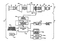
As shown in FIG. 1, a rotating machinery system 10 includes electric
power generation system 12 and control system 14.
Steam is delivered to electric power generation system 12 from a steam
source (not shown). System 12 comprises a main shaft 16, mounted in bearings
18. Low-pressure turbine 20, high-pressure turbine 22, generator 24, and exciter26 are connected on shaft 16. A bull gear 28 is a~so mounted on shaft 16. Bull
gear 28 has N teeth. (A typical turbme shaft's bull gear has from 60 to 140
teeth,) The foregoing ~ of system 12 are Cu~ iivl~l devices typically
found on a turbine-generator set.
Control system 14 comprises sensor 30, sensor interface 32, pulse-rate con-
verter 34, processmg unit 36, and various units peripheral to processing unit 36,
which are described below. Sensor 30 provides a signal I~ Il~iiV~ of shaft
rotation rate, as described below in section Il. That signal is ''' ' and
processed by sensor interface 32, pulse-rate converter 34, and processing unit 36
to provide resonance i~f~"~ ..--data about resonant vibration ~,h~
over time for shaft 16 and turbine b~ades of turbine 22, and to provide informa-tion about changes that occur in such data as described below in sections III-V.In FIG. 2, an i".~ i,... is shown for providing resonance illfUllll~l~iUII
primarily about the shaft of a vertical pump system (such as a coolant pump).
Here pump system 60 comprises an electric motor 62, having a shaft 64, to which
pump 66 is mou~ed. An encoder gear 68 is also mounted to shaft 64, and it
operates in a manner similar to bull gear 28 in FIG. 1. Sensor 30 and sensor
SUBSTITUTE SHEET (RULE 26)
WO95/27183 2 1 9 2 1 8 2 PCTNS94/03736
--7--
interface 32 cooperate with gear 68 in a like manner as that described above. The
other parts of the system are not shown again in FIG. 2, since they operate in the
same manner as in FIG. l.
While the steam turbine system of FIG. l was described in terms of a
horizontal shaft ~l , the invention is in no way restricted to such operation.
The invention operates in the same way for a vertically-oriented turbine, and it is
also suitable for use with hydraulic and gas turbines in the same manner as de-
scribed for the steam turbine of FIG. l. The invention is also applicable to other
types of rotating equipment having elements, such as propeller blades, helicopter
rotors, and pump vanes, that may resorlate.
As explained in greater detail below, turbine blades have resonant vibration
modes and they oscillate as they rotate around their shaft a~is. The oscillationalterrlately imparts and takes angular from the shaft and thus the entire
rotating system. When a blade imparts angular mom~nnlm to the system, the shaft
speeds up slightly; when a blade takes angular from the system, the
shaft slows down slightly. The result is to vary the rate of angular rotation of the
shaft by a slight amount, at the resor~ant rll ~ of the blades. A like reso-
rlance effect occurs as a result of excitation of shaft torsional resonant modes.
Indeed, the principle extends to any rotating system having r ' that can be
excited in a resonant mode so that they oscillate and then impart angular momen-tum to, and take it from, the rest of the rotating system. The ;~, and
signal-processing apparatus of this invention uses the foregoing changes in rate of
angular rotation to ascertain the resonant r~ of the oscillating ~ r
of the rotatimg system, as explained below in the following sections of the specifi-
cation.
The principal discussion herein is directed to machines (such as turbines
and pumps) having rotating parts that extend radially outward from a shaft and are
rotated by it. However, the invention can be practiced with any rotating part that
- is attached to a shaft and imparts angular to the shaft at resonant vibra-tion rl~ l.,;~ of the part. Thus, a disk or annular part attached to a shaft canmodulate shaft rotation frequency by resonant vibrations of the part. Indeed, aspointed at in various places in thls ~ ;.." the shaft itself has resonant fre-
SU~STITUTE SHEET (RULE 26) __ _
WO951~7183 2 1 9 2 1 ~ 2 PCTIUS9~/03736
--8--
quencies (associated with torsional vibration) and its own oscillations modulate its
rotation frequency at such frequencies. Thus, the invention is not restricted toradially extending machine c~ but instead l.;Ulll,UlCh~ any component
that the shaft of a rotary machine rotates, and from which the shaft receives angu-
lar m-lm.~nnlm at a resonant frequency of the ~-r~mrnn.~nt
In addition, the invention extends to systems not having a Cull~.,.lLiul~l,
ihlriin~lly- , cylindrical shaft. The system may have a camshaft,
instead, in which the shaft is not shraight but is zig-zagged or l~luylillLhi~. Mûre-
ûver' the system need not have a CU..~,I.iiul~l shaft at all, as m the case of apinwheel-like device, such as a radiometer, in which blades or rotors rotate around
an axis to which they are not affc~ed. The basic defining ~ ;,. of the
rotating machines to which the invention is applicable is that the machine must
have one or more r~ that can be excited to oscillate in one or more reso-
nant modes, and that the oscillating ~ c) must be able to impart angular
mr~m~nn~m to the rûtatmg system and withdraw it, in the course of such oscilla-
tions.
Il. Sensor
Referring again to FIG. 1, sensor 30 is preferably a magnetic transducer
picking up the motion of the teeth of a steel gear as they pass the hransducer. But
the sensor may be l l ' instcad as a ~hJLu~ ,LIi1 detector or other optical
sensing device, as a proximity (~ or cddy-current) detector, as a tachom-
eter producing an ouhput whose amplihude is IJlupulLiul~l to shaft speed, or anyother convenient means of detecting angular rotation frequency of shaft 16. How-ever, the sensor is preferably one capable of responding directly to shaft rotation
rate. Thus, the inventors have not found it practical to use ~II~IUA~ or
vibratiûn pickups to measure l ' ' of shaft rotation rate by ~,.".l....,. :~
rotated by the shaft, because they pick up too much noise from other vibrations in
the system and this sensor ouhput does not lend itself to practical extraction of
j" ~ r~ shaft rotation rate data.
Bull-gear rnagnetic sensor
In the presently preferred magnetic hansducer j",~,l...,..,~l;~", of the sen-
sor, as each of the N teeth of bull gear 28 passes sensor 30, the tooth induces a
SUBSTITUTE SHEET (RULE 26)
WO 95/27183 2 1 9 2 1 8 2 PCT/lJS9i/03736
_9_
"blip-like" signal (hereinafter referred to as a "pulse") Ic~l~.c.l~live of shaft
rotation. Thus, each time a tooth passes, a pulse is generated that indicates thdt
the shaft has rotated another d~)lJII ' ' Iy 360/N. The pulses produced by
sensor 30 are shown in FrG. 3a as pulses P. As a practical matter, the teeth of a
bull gear are not spaced at perfectly equal angular intervals, so that each pulse
represents an increment of angular rotation that is (360/N) ~ x, where x is a
small variation. These small variations give rise to spurious modulation signals(" rcl~ c") that appear in Fourier Transform spectrums as harmonics of the
30 Hz or other r~ 1 shaft rotation frequency. Such ill~lrC11111,~; is reduced
by signal-processing expedients discussed below.
Sensor interface 32 activates sensor 30 and conditions the analog signal
output by filtering, dllllJIirl~,dLiUII, and dc level-shifting. Interface 32 converts
pulses p of FIG. 3a to pulses P' of FIG. 3b, which are "cleaned up" versions of
pulses P of FIG. 3a. Interface 30 is 1 l ' by any of a number of conven-
tional circuits, whose application here is obvious to persons of ordinary skill in
circuit design. This circuitry eliminates noise and insures one and only pulse P'
for one pulse P.
Optical/magnetic tape sensor
As indicated above, other forms of sensor can be used in practicing the
invention, and the invention is not limited to use with the magnetic sensor de-
scribed above. For example, as shown in FIG. 4, a tape 50 having reflecting
bands B at regular intervals can be epoxyed or otherwise affixed to the main shdft
of the turbine with bands B parallel to the axis of the shaft. A laser or light beam
52 then i~ .," tape 50 with pulses L. The light frequency may be visible,
W, or IR. Pulses L are reflected off bands B of tape 50 as pulses L' and are
received by receiver 54. (It is preferable that tape 50 have dlJ~II 'y the
same thermal coefficient of expansion as the shaft to which it is affixed, so thdt it
will not deform, thereby illL I ' ~ a noise signal.)
Tape ~0 may instead be ,, lly "marked," that is, have small magnet-
ic zones affixed thereto, so that the tape can actuate a magnetic sensor. The mag-
netic-sensor approach has the advantage of being less sensitive to the presence of
grease and dirt than an optical sensor. Both the optical and magnetic band ap-
SUBSTITUTE SHEET (RULE 26)
WO 95/27183 2 1 9 2 1 8 2 PCT/US94/03736
proaches are a.lv~u.L~ .u~ when a bull gear is not available at a desired shaft
location or when a number of pulses per rotation is desired that differs from the
number of teeth on the gear.
Nyquist constraint
A constraint on selection of pulse-producing sensors should be noted. The
kind of signal processing and analysis used in the invention, described below, calls
for a sampling rate for the parameter being measured (shaft rotation frequency as
modulated by rwonant-mode r~c~ of shaft and bladw) that is well in excess
of the highest frequency of interest. 1~ ~ of large stearn-turbine blades
requires deoection of shaft-speed ~--n.l~ up to 200 Hz or higher. An 80-tooth
bull gear providw 2400 pulses per sec (80 teeth x 30 Hz). According to the
Nyquist Theorem, that 2400 pulses/sec allows analysis of m~ ~ ' " signals up to
1200 Hz. The integration time constant of the frequency-to-voltage converter used
here (described below) reducw this frequency to the 400 to 600 Hz range. That istwo to three ti}nes the rl1~1~11,;.,~ required (200 Hz) for large steam-turbine
blades, so that there is no problem. However, this factor would have to be takeninto account in selecting sensor ,,,,IJ!..,... '-1;ll for other rotating machines hav-
ing different rlc.~ ~;w of interwt.
AC-output detector
In principle, the mnti~ tinn of angular rotation frequency of the shaft
induced by turbine blade oscillations could be exrracted from the 60 Hz output of
generator 24. However, by that stage of the system, the ' ' ~ frequency
induced by blade rwonance have been greatly filtered out to very low
signal levels by mechanical and other filtering elements in the system. Neverthe-
lws, use of ~' ' of AC output from a turbinc g~ ul set, or an equiva-
lent signal, is considered within the scope of the invention.
Thus, an ~p~lu~ t~_ly 60 Hz signal can be taken from generator 24. (An
electric power generator operatw at too high a voltage to be used directly, and
must be stepped down for the present purpose. Typically, power alternators have
associated with them step-down 1I r that provide low-voltage signals.)
That provides a signal lc~lLS.~Il~Live of i~ u~ shaft rotation-frequency,
which includes signals lci~Jlc~ lL~ive of l ' l~rinn of shaft rotation-frequency
SUBSTITUTE SHEET (RULE 26)
WO 95/27183 2 1 ~ 2 1 8 2 PCT/US94/03736
~aused by resonant oscillations of the shaft or other rotating elements. The differ-
ence between that frequency and exactly 60 Hz represents the signal of interest.The difference signal of interest can be obtained by any of several uu~ Li~Lal
processing sign~l t~ iuu~ based on signal phase ~,UUUp~uia~/ll with reference
signals and the extraction of i~ frequency Ill~aaUICLU~llL~.
The foregoing sensors are referred to as providing signals "I~;,UI~a~ iaiiVt:
of angular rotation" of the shaft of a rotary machine. That concept is intended to
include provision of signals indicative of absolute value of shaft rotation rate or
change in shaft rotation rate, and also to include absolute value of shaft angle or
change in shaft angle. Thus, to monitor ".n.l"l~;.",~ in shaft rotation rate caused
by vibration resonances of parts such as turbine blades and shafts, it may not be
necessary to determine whether the shaft is rotating at 30 Hz or 31 Hz. What
needs to be measured is the ~ J~1, for that is what is indicative of the vibra-
tion resonances of interest. Hence, a sensor that is capable of accurately picking
up changes in shaft rotation frequency can be effective for purposes of the inven-
tion ill~ iv~ of whether the sensor is capable of accurately picking up absoluteshaft rotation frequency. By the same token, sensors useful for practicing the
invention may accurately read changes in shaft angle without also accurately read-
ing absolute shaft angle.
If the application warrants, additional sensors and shaft elements to cooper-
ate with them may be retrofitted to other shaft positions along the shaft axis,
which may provide enhanced sensitivity for measuring the resonant rl~ of
interest. The inventors consider this expedient a matter of design choice and not a
part of the invention.
llI. D ' '-ion
The inventors' preferred, ~ ' for ~ "~ fre-
quency of shaft rotation is the pulse-rate converter described below. However,
frequency can be determined simply by feeding the pulses to a high-
speed counter and resetting it at each pulse. If there were no mn~ tin~ of the 30
Hz shaft rotation-frequency or variation in intertooth spacing, the time betweenpulses would be a uniform l/30 x l/N sec, where N is the number of teeth on the
bull gear. Thus, an 80-tooth bull gear produces 2400 pulses per second, with a
SUBSTITUTE SHEET (RULE 26)
WO95127183 2 ~ q 2 l 8 2 PCTIIJS9~/03736
time of 1/2400 sec = 417 microsec between pulses. That figure may be consid-
ered a reference elapsed time, from which elapsed time lc~.c,.ll~iivc of changesin i.~ frequency reflecting blade resonances will differ by r~
That difference time can be converted into a signal which is subjected to Fourier
Transform analysis to provide resonance illrulul~liiu... However, it will be appre-
ciated that a very high-speed counter is needed to obuin useful ;"r.... -,;....
Accordingly, the following circuitry is considered preferable.
P~lse-Ra~e Converter
The output of sensor interface 32 (see FIG. 3b) is fed to pulse-rate convert-
er 34. The function of converter 34 is to convert the cleaned up pulses of FIG. 3b
to a voltage IC~llC~ iv~ of pulse frequency. The specific pulse-rate converter
circuit now described is designed for a system with the following parameters, but
the circuitry may readily be adapted to other systems by persons of ordinary skill
in designing circuits.
For a typical 80-tooth bull gear and 30 Hz turbinc-g~ ,...wl, the pulse
repetition rate is 80 x 30 = 2400 Hz. The resonant frequencies of interest are
from ~ 10 Hz to 150 or 200 Hz. (For the specific steam turbine for
whose testing this particular pulse-rate converter circuit was designed, the lowest
frequency of interest was 19 Hz and the highest was ~ , 150 Hz.) The
main ~ rl~ . of interest are those due to the lower-frequency
exciution modes of the large blades of the turbine. They generally may occur in
the range from 60 Hz to 200 Hz; under normal operating conditions, they can
modulate the 30 Hz r. ..l~..l. ,-l of the system in the range of 30 :t 0.0005 Hz.
Also of interest are lower-mode turbine-shaft torsional resonant rl" gener-
ally occurring in the range from 10 Hz to 40 Hz.
FIG. 5 provides a detail drawing of pulse-rate converter 34 of FIG. 1. The
output of sensor interface 32 is fed to the input of converter 34, which processes,
integrates, and filters signals l~ iVC of O~ ~ of pulses P and P'.
The output of converter 34 is a dc-shifted signal whose amplitude is linearly plo-
portional to pulse frequency, and thus linearly ~u~Ju-~iull~l to _ rou-
tion frequency of the turbine shaft. Converter 34 thus provides an output voltage
V~, which is ~ .Ulliu..al to the frequency of pulses P and P'. FIG. 3c shows a
SUBSTITUTE SHEET (RULE 26)
WO 9S/27183 -13- 2 1 9 2 l 8 2 PCT/US94/03736
voltage Vj IC~ .lULiiVC of an integral of pulses P', and a dotted line which is a
moving-time average of V;, provided by ~ )IU~JI' ' ~S/ filtering it to provide fil-
tered output signal Vf. The details of this procedure are now described.
As shown in FIG. 5, cleaned up pulses P' of FIG. 3b are fed to a bandpass
filter 70, having a 0.1 Hz to 10 KHz pass band. Filter 70 removes the dc compo-
nent of the input signal and attenuates high rl., The output of filter 70 is
fed to voltage divider 72, which further attenuates the signal, for example, by a
1:2 factor.
The signal is then fed to 20 Hz 4-pole high-pass filter 74. The output of
filter 74 is fed to an operational amplifier 76, configured as a ~;u..l~)~awl having a
voltage V (for example, 0.5 v) for threshold/reference ~ t~nt
When a pulse input to operational ~lir.~./, , 76 exceeds the thresh
old/reference voltage level, operational ~"lirl~l/, r ' 76 changes its output
state from 0 v to 5 v.
The output of nr~r~tin~ ,IirlL,./, , 76 is delivered to capacitor-
resistor ' 78, which removes the dc component and passes higher fre-
quencies. Appropriate values for capacitor-resistor . ' 78 are 270 pf and
4.7 K.
Capacitor-resistor ~ ;", 78 passes a positive spike to a frequency-to-
voltage converter (FVC) 80 at the begmning of a pulse P'. FVC 76 is convenient-
ly an Analog Devices AD650 chip. Each time a positive pulse triggers the AD650
chip, it provides a current pulse of l ' ' duration and amplitude to an
integrating capacitor 82. The AD650 chip ignores negative inputs, so that it does
not respond to the negative spike caused by the trailing edge of the pulse output
from, , 76.
Capacitor 82 integrates the current pulses in accordance with the formula
V = (l/C) x I i dt = Q/C,
where C is the value of capacitor 82. The AD650 chip used here as FVC 80 has
a calibration resistor 84 connected across capacitor 82. Resistor 84 is used to
adjust tne output of the AD650 chip to a desired full scale value. Here it is de-
sired that full-scale voltage be 10 v for a pulse-repetition rate of 2400 per second.
A convenient value for resistor 84 is 220 K in series with a 50 K pot.
SUBSTITUTE SHEET (RULE 26)
WO 9!;127183 2~ ~ 2 1 8 2 PCI;'US94/03736
--14--
The output of FVC 80 is a voltage V~ shown in FIG. 3c, a series of trian-
gle waves whose frequency is the frequency of pulses P and P'. The integrating
side of the triangle is very steep, but the leakage or decay side is much less steep,
as a result of the time constants associated with charge and discharge of capacitor
82. The height and width increments for the steep side of the triangle are always
the same (V=Q/C). But the height atld width increments of the descendmg side
of the triangle vary in accordance with pulse spacmg (or, cuuiv ' '~, irlstanta-neous pulse frequency), since the descending side is an r '' ~ decay function
dependent on how much time elapses until the ne~t current pulse occurs.
The output of FVC 80 is fed to an operational arnplifier 86 via a series
resistor-capacitor ~;u..L~liul~ 88, which removes dc. Appropriate values for
series resistor-capacitor ~ ;.)" 88 are 10 K and I llf. Operational amplifier
86 has as a feedback loop a parallel resistor-capacitor . ~ 90, 10 K and
22 nf, providing unity gain at low frequency and attenuation at higher rlc.~
Resistor-capacitor . ' 90 thus acts as a prefilter for low-pass filter 92, to
which the output of operational amplifier 86 is next fed.
Filter 92 is a 150 Hz 8-pole low-pass filter. The smoothed (averaged)
output voltage Vf (shown as a dotted Ime in FIG. 3c) from filter 92 is then fed to
processing unit 36, as described above. The 150 Hz filter was inserted for anti-aliasing purposes before sending the signal to an analog-to-digital converoer. The
150 Hz cutoff value was selecoed to eliminate frequencies above 150 Hz, because
they were of little inoerest in the case of the turbine that this unit was designed to
oest. If frequencies, for example, of up to 200 Hz were of inoerest, it would benecessary to raise the cutoff frequency of filoer 92 to ~ them.
Voltage Vf is an analog signal whose i -..l~,...,"~ value is ICIJI~ ' ''~.
of the raoe of shaft rotation. The raoe is, in the system described above, 30 Hz i
small ' ' occurrmg at various frequencies. As stated earlier, the main
rl~ I of inoerest for large low-pressure turbme blades is in the
range 60 Hz to 150 or 200 Hz, of amplitude ~ i 0.0005 Hz. Shaft
torsional resonance n~nt~ tinn of a frequency in the range from 10 Hz to 40 Hz
may ~I,CUUI,UcUl,y such blade resonance. The frequencies of interest occur in the
presence both of ~ noise and of harmonics of 30 Hz.
SUBSTITUTE SHEET (RULE 26)
WO95/27183 -15- 2 1 92 1 82 PCT/US94/03736
As indicated previously, the sensor described above updates the value of in-
"l~ frequency d~ y 2400 times per second (30 Hz x 80 teeth).
Such signal illru-luG~iu.. is G~p U~, for detection of signals up to 1200 Hz,
based on the Nyquist Theorem. But the time constants of the foregoing demodula-
tion circuit reduce the 1200 Hz figure to an effective 400 Hz to cut-off frequency;
that value is ' ' well in excess of the 60-200 Hz r.~ u~,;~ of interest for
large steam-turbine blades. How to adapt the foregoing circuitry to different
rl~4~ ~ of mterest is obvious to persons skilled in design of electrorlic circuits.
Direct use of pulses
As an alternative to providing analog signal Vf, pulses P may simply be
~.., i;li."..~1 and fed to processing unit 36. In this approach, no frequency-to-
voltage conversion ~J~c~lu~ hlg step occurs. However, the pulses may first be
' to remove noise. This is done by CUIl.~,lliiuucll means,
In either case the pulses or signal Vf must be processed within processing
unit 36 to extract from the ~ noise and harmonics the signals of interest
which are induced by ' ' of the 30 Hz shaft rotation rate by blade and
shaft resonant [l~u~
IV. Processing Unit
The signals provided by the above mearls are fed to processing unit 36.
Processing unit 36 extracts the resonant-frequency signals of interest from noise
including shaft rotation-frequency harmonics, as described below in section V. In
addition, processing unit 36 analyzes data concerning the resonant-frequency sig-
nals of interest in accûrdance with procedures described below in section VII.
This method is CUAIV~UI~ Y ill.~ with an IBM PC-386 personal
computer, based on an 80386 Illil.,lUplULC~.~JI chip, as a processing unit. Howev-
er, a one-board Illi~,~u~uul,u~.~l as a commercial standalone unit, or other micro-
processor or microcontroller chips, may be used, instead, depending on design and
commercial ~ c~ ;""~ The invention is not limited to i ~ with
any particular processing unit.
r~ G/Ul.~
Processing unit 36 is optionally coMected to a variety of peripheral units.
When the invention is used simply to measure resonance illrulluGiiuu for a compo-
SUBSTITUTE SHEET (RULE 26)
WO 95/27183 2 1 9 2 1 8 2 PCT/US94/03736
--16--
nent, the peripherals are used just to provide that l"r.., ,,.-l ;..,, When the invention
is used to determine whether changes in resonant vibration clldldclcli~ii~ are
occurring that indicate ~lu~u~,Live failure of a r,nmrnnPnt the peripherals are used
not only to generate reports or provide ;,.r..".~-~;.", but also to alert operators or
control-room personnel by visual and/or auditory means, and also in some applica-
tions to shut down the equipment before a failure occurs.
Referring to FIG. 1, shutdown means 38 shuts rotdting machine 12 down
when processing unit 36 detects an imminent failure, such as a blade or shaft
fracture. When processing unit 36 detects such UlU~ ,LiVC l,dl~llU~/hil, failurecondition, by means described below, unit 36 sends a shutdown signal to shutdownmeans 38. Shutdown means 38 then shuts system 12 down, by stopping power
delivery thereto, for example, by shuttmg off steam delivery to the turbines and/or
venting steam therefrom. Preferably, this is ~ h d in an orderly malmer,
following a ,ulcd~ d shutdown routine. In the case of a device driven by an
electric motor, such as the pump of FIG. 2, the shutdown means open the electri-cal power input line to the device.
In the present state of the art, it is believed that the _ of electric
power generation facilities will be unwilling to permit automatic shutdown of
stedm turbines simply because a computer device indicates thdt shutdown is appro-
priate. (That is not necessarily true in other ~rrlir~rinn~ of the invention.) Ac-
cordingly, it is presentdy ~ .' ' that a shutdown alarm signal will be pro-
vided, and that an engineer will then examine the data on which the alarm signalwas generated in order to determine whether he agrees that such data warrant a
shutdown. The inventors: .' that as this invention proves itself in the
industry, and as more experience is gamed with resonance ;"r.,."-- ;.... mdicative
of an impending ~IL~u~l.i-; failure, it will become acceptable to the industry to
operate in an automatic shutdown mode. Accordingly, the invention ~OLI~
both alarm and shutdown modes of operatiûn. Monitor 40a ~:UII~ y dis-
plays waveforms, spectrums, and/or historical data, such as a skewness of a reso-
nant frequency around its mean, kurtosis of a resonant frequency about its mean,and formation of secondary resonance peaks (discussed in section VII-B). Such
data is provided by processing unit 36. Printer 40b prints data and other informa-
SUBSTITUTE SHEET (RULE 26)
WO 95127183 2 1 9 2 1 8 2 PCT/US94/03736
-17-
tion provided by unit 36. Alarm 40c is a visual or auditory adjunct to, or substi-
tute for, shutdown means 38. Keyboard 42 is a convenient means for inputting
additional illrul~uaiiul~ to unit 38" " ,, reports, or otherwise directing tâsk
~. . r..",.~,.. r. Ports 44 provide unit 36 with additional input and output of infor-
mation.
Spectrum analyz~r i7n~ ""
A simplified i",~ ;,.., of the invention dispenses with the elaborate
signal-processing procedures described below and with the processing unit that
carries them out. Instead, a ~ ly available, off-the-shelf spectrum analyz-
er (such as the Zonic A/D 3525 Dual Channel FFT Analyzer) is used to observe
the signals described earlier.
This approach provides spectral ' ~UllUaLiull of the kind described below,
so that at least some of the resonânt r.~ . of interest can be observed. This
approach allows elimin~ti-m of i~ rcl~ t by shaft harmonic r~ u.,~i~, when
sylll,lll~ techniques described below (section V-B) are utilized through addi-
tional external electronic circuitry. This approach also allows use of ~zoom analy-
sis~ to obtain high resolution of spectral resonance r,.. of interest. How-
ever, this approach does not permit use of the below-described special ll~;.,~-, '
nation techniques, trend analysis, and automatic alarm and shutdown ~re~ nt~
It is therefore not - . 1 ' as a preferred ~ ~ ' t, but rather just as a
convenient portable diagnostic device.
V. Signal Processing
The procedures for signal processing that are involved here may advanta-
geously be illustrated with reference to signals induced by vibration of turbineblades. A typical large-turbine blades rotates at 30 or 60 Hz, and my be 4 feet
long, weighing 4û pounds. A single stage of a steam turbine typically comprises
60 to 140 such blades. In normal operation, llyLudy forces may deflect the
individual blade-tips ~ 0.0001 inches at a principal mean resonant frequency (for
example, 78 Hz). The blade thus oscillates slightly at that frequency around itspoint of attachment to the shaft. As a result there is an alternating positive and
negative transfer of angular ~rlnn.^ntll~l from the blade to the shaft and thus to the
entire rotatmg system. This alternating plus and minus transfer of
SU~ST~TUTE SHEET (RULE 26)
WO 95/27183 2 1 9 2 1 8 2 PCTNS94/03736
-18- ~--
modulates the shaft rotation frequency. The amplitude of such mn~ rinn is
related to the ratio of the blade angular momentum to the angular mnmPn~l~m of
the entire rotary system (turbine, generator, etc.).
The frequency of angular rotation of the shaft has a 30 Hz main compo-
nent, which is modulated, in this example, by an 78 Hz component (among oth-
ers). The 60 to 140 blades of a stage are very similar in size and shape, and
typically have resonant rl-u,.._u,,;~,~ within a :t2 Hz bandwidth of a mean resonant
frequency for the set of blades. Subsets of these blades (for exatnple, 5 to 10)may be TnPrh~ni~lly conmected to form groups of blades; that has the result of
causing such groups to have group resonant vibration ~ u~Lcli,Li~;~, which the
system of this invention also monitors.
3FIG. 6 illustrates these effects, based on the inventors' theoretical calcula-
tions and their empirical Ub..~ iiUlJ.s discussed below. It is seen that a very
small-amplitude 78 Hz sine wave modulates the 30 Hz shaft-rotation frequency.
The result is a rotation frequency swing from ~JIl 'y 29.9998 Hz to
30.0002 Hz. Usmg a bull-gear encoder of the type previously described involves
a 2400 pulse/sec signal. The ~' ' described places a several ~
(for example, 5 nsec) variation in pulse spacing in a pulse train havmg an approxi-
mately 420 I~ ,lu~ul~d interval between pulses. That is the type of signal that
must be extracted from the sensor signals and iiCCUlU~ illg noise, to detect these
resonant frequencies. rml c, to meacure small changes in such reconant
rlc.lu~l.,,;w involves even smaller signal-to-noise ratios.
A signifcant amount of i..~.f~l~c occurs at harmonics of the fundamen-
tal frequency--30 Hz. These interfering ",..1~1-~;...,~, which are much greater in
amplitude than the ,---~li l,.ii...,~ of interest, are u~ J;ddl~l~ artifacts of the system.
For example, bull gear 2B will typically have variations in the spacing of its Ngear teeth. The effect of this repeats every rotation, so that there is an apparent
(but ~ ) rotational speed variation based on 30 Hz and its harmonics.
Other imh~ n~Pc, miC~ nmPntC, and loads in the rotatmg system will create
variationS in shaft rotational rate and repeat for each rotation. (The foregoingstalements concerned a machine with a 30 Hz r,.",l~".. .,1~1 A machine having a
60 Hz r.,.,.l~.,, ,1-l has harmonics that are multiples of 60 Hz rather than ûf 30
SUBSTITUTE SHEET (RULE 26)
wo 95/27183 2 1 ~ 2 1 8 2 PCTIUS94/03736 ~
Hz.)
The basic tool that the inventors have used to extract signals of interest
from the iu~lrclcll.,e found in the sensor signals has been the Fourier Transform.
T,.. l,l.. :-l;.. ~ are described below using both Fast Fourier Transform (FFT)
and Discrete Fourier Transform (DFT).
As previously indicated, pulse-rate converter 34 provides a ~ rn~
output voltage signal lc~ K~Live of pulse frequency; ~ ,ly, the pulses
are used directly after c-- lil;-~--;- ~ them. Whether the pulses are used directly or
after frequency-to-voltage conversion by pulse-rate converter 34, the pulses maybe subjected to either FFT or DFT analysis and the results may be examined.
This approach leads to data such as that shown in FIG. 10, in which there is a
great deal of off-scale mnr~ tinn shown at n x 30 Hz, where n = 1, 2, 3 ....
Instead and preferably, whether the pulses are used directly or after fre-
quency-to-voltage conversion by pulse-rate converter 34, the pulses are then sub-
jected to a DFT or FFT analysis in which special measures are taken to eliminateharmonic ill~.rcl,,l.~e. These f~l~lLc-removal techniques are based on a
primciple that the FFT or DFT analysis of signals depends on the choice of fre-
quency points at which shaft-rotation frequency amplitudes are observed. A typi-cal FFT or DFT analysis ascertains frequency amplitndes at a given number of
spectral [l~uU~ ;C~, which are spaced from one another by ~.~.I ~, ,..i....l fre-
quency intervals. The selected spectral r., I are sometimes referred to as
rspectral bins,~ but it should be understood that a Fourier Transform spectrum
analyzer provides signals ICpl~ ' 'VC of amplitnde and phase at a series of
.lll;...A discrete data points, such as exact 30 Hz, rather than amplitudes
and phases associated with some range such as 30 Hz :~ 0.001 Hz.
When a signal of particular frequency interferes with Ul~lV~ ll of a
frequency of interest, it is important whether the interfering frequency coincides
with one of the ~.~ ' ' FFT or DFT spectral rl. l For example. in
this case 30 Hz is an interfering frequency. If there is a spectral frequency of
exactly 30 Hz in the DFT or FFT, all of the 30 Hz signal will be registered at that
location. But if spectral r., I occur instead at other values, such as 29.5 Hz
and 30.5 Hz rather than 30 Hz, the 30 Hz iUl~ ,C signal will ~leak~ or be
SUeSTlTUTE SHEET (RULE 26)
WO 95/27183 2 1 9 2 1 8 2 PCT/U594103736
--20--
smeared over or among many adjacent spectral bins along the frequency axis. The
amplitude of the leakage diminishes as a function of frequency difference from the
interfering frequency value (here, 30 Hz). Such smearing is pal Liuulally evident at
the lower power levels that ull~ua~ i~ the shaft-rotation-modulating r,~
of interest here.
An important element of the techniques used in this invention (described
below) is therefore that, to eliminate the foregoing illitl~ uu~ the Fourier Trans-
form spectral rlt~lu~ must be made to coincide with the dominant interfering
r,.,.~u~ . Here, that is the 30 Hz sbaft rotation frequency being modulated and
its harmonics (such as 60, 90, 120, and 150 Hz).
A first technique for removing harmonic iu~lrtl.,.,~t, used with DFT
analysis is described (Section A, below). Then such techniques for use with FFT
analysis are described (Section B, below). Direct analysis of the encoder pulse
train, without frequency-to-voltage conversion, is next described (section C, be-
low). An extremely effective technique for removing other sources of iu~lrtl~,u~c
is last described (Section D, below).
A. ~ f~ e ~educ~on - DFTTec~ e Using F/VConverrer
Converter 34 provides a voltage whose amplitude is ~,u~u,~iu,~l to instan-
taneous frequency. The voltage is then converted to a digital signal by a conven-
tional analog-to-digital converter (ADC) tbat is clocked with the pulses P'. Pulses
P' are used to clock tbe ADC in order to permit the length of the data record that
the ADC uses for analog-to-digital conversion to be set at an integral multiple of
N, where N is the number of teeth on the bull gear and thus the number of pulsesoccurring per complete shaft rotation. The data is acquired from M shaft rotations
for the DFT analysis, so that the data record length is N x M. (For example, fora 120-tooth bull gear, and a value of M = 100, number pulses in data record = N
x M = 12,000. That means tbat the data record conuins data for 100 complete
shaft rotations. That is 3.33 sec.)
Since pulses P' are at a~ ly 2400 Hz, the ADC is sampled at a
much higher rate than necessary to satisfy the IL~IUiU~,lll~,U~ of the Nyquist Theo-
rem. Here, the highest frequency of interest is a~ Iu~diLua~ly 200 Hz. Hence, a
sample of 600 Hz is more tban adequate. Accordingly, the inventors prefer to
SUBSTiTUTE SHEET (RULE 26)
-
WO 95/27183 2 i ,~ 2 ~ 8 2 PCTIUS94/03736
--21-
feed pulses P' to a ~ iUllal divide-by-4 circuit before using the pulse train toclock the ADC. That permits use of less c..,..l."~ resources.
The data record is then subjected to a DFT analysis. Because the user is
free to set the data record to be N x M pulses long for DFT analysis, these binswill necessarily include 30 Hz, 60 Hz, 90 Hz .... That occurs because, in a
Fourier TraDsform, the lowest spectral frequency iu~.~DI,u.ld, to one complete
cycle with a period equal to the time for N x M sensor pulses. Therefore, a datarecord from N x M sensor pulses contains data from M complete shaft rotations.
Thus, the 30 Hz ' ' ' frequency is found at the Mth spectral frequency, the
next harmonic (60 Hz) is found in the 2Mth spectral frequency, the next harmonic(90 Hz) is at the 3Mth spectral frequency ... and the last harmonic registered is at
spectral frequency N x M/2. Thus, if a data record contains 10 data segments,
and N = 120, 30 Hz will be at the 10th spectral frequency, 60 Hz at the 20th, 90Hz at the 30th, ... and 1800 Hz at the 600th spectral frequency. CThese counts
omit the zero spectral frequency.)
The result of the foregoing procedure is to identify a series of spectral
lines, as shown in ~IG. 7. A moderate peak is shown at 78 Hz, the resonant
frequency of the turbine blades for this example. Higher peaks are shown at 30,
60, 90, 120, and 150 Hz. These represent the 30 Hz ' ' I of the system
and its harmonics. Shown as a dotted line I in FIG. 7 is a ~ .,LLiull of the
leakage ( ' ~c) that would occur at each of the shaft-rate harmonic frequen-
cies if spectral r.~ . did not coincide with 30 and its multiples.
The peak at 78 Hz is not a line at a single spectral frequency, as the har-
monics are, for several reasons. First, blade resonance is not a frequency in step
with shaft rotation, as the harmonics are. Hence, the foregoing procedure cannotconfine the signal to one spectral frequency. Second, there is not a single blade
' ' ' resonant frequency, but rather a different ' ' ' resonant fre-
quency for each of 60 to 100 blades for a turbine stage. These are distributed
around a mean r,, l~ 1 resonant frequency, for example, 78 Hz ~: 2 Hz.
B. In~"~fe/ ~ e Reduchon - FFT Technique Using F/V Converter
The FFT, unlike the DFT, does not permit an arbitrary selection of the
number of points in a data record. The number must be a power of 2, such as
SUE;STITUTE SHEET (RULE 26)
WO 9~/27183 2 1 9 2 ~ 8 2 PCTNS94/03736
-22-
512 or 1024 (which are two convenient values). To achieve a nulling effect simi-lar to that described in the preceding section, the data record must have two char-
acteristics. First, the data record must include a number of shaft rotations equal to
an integral power of two; second, the number of data points read per shaft rotation
(i.e., number of data points in each data segment) must be also be an integral
power of two.
Converter 34 provides a voltage Vf whose amplitude is UlUpUl~iUII~I to
i"~ frequency. Over an mtenal of 1/30 sec, one complete shaft rotation
occurs. That interval (data segment) can be divided up for ADC purposes in any
way; the number of intervals within the data segment does not have
to be the same as the number of pulses from which Vf was originally derived. At
every moment, there is available at the output of converter 34 an analog voltageVf that is l~ iV~ of the value of shaft-rotation frequency at
that time. Every moment is a possible data point. Accordingly, the processing
unit can direct the ADC to read (sample) the analog voltage Vf at whatever inter-
vals or data points are desired.
Thus, the number of data points at which Vf is read during each 1/3û sec
interval (data segment) can be 128, 256, or amy other convenient number. (How-
ever, the number should be at least high enough to meet the Nyquist criterion that
sampling raoe must be at least t~vice the highest frequency of interest).
Here, we assume a 100-tooth bull gear, producing 100 sensor pulses per
shaft rotation. A number of data points per shaft rotation equal to a power of two
--in tbis example, 128--is provided by means next described. Accordingly, every
data segment containing data from N pulses (here, 100 pulses), comprising data
from one complete shaft rotation, shall be divided into a number of points at
which Vf is read. The number is to be an integral power of 2, such as 128. Thus
the frequency-to-voltage converter output from 100 sensor pulses provides a vary-
ing Vf value over a 1/30 sec intenal. The value of Vf is sampled 128 times for
analog-to-digital conversion, because the ADC clock is enabled 128 times during
the interval in which 100 sensor pulses occur.
The 128 clock pulses for every 100 sensor pulses are provided as follows.
First N pulses P' are fed to a LUII~..iU~I computer-controlled phase-lock-loop
SUBSTITUTE SHEET (RULE 26)
WO 95127183 2 1 9 2 1 8 2 PCTIUS94/03,36
~ --23--
pulse multiplier-and-divider circuit. (That circuit is uu~ Lly i~lul~ d
with a Motorola MC14046B chip, which contains a phase ~UIII~ UI and voltage-
controlled oscillator (VCO).) The N pulses provide an ~u~u~d~ ly 1/30 sec
intenal ~C~Ult~CillL~l~iv~ of one complete rotation of the shaft.
The N sensor pulses are fed to one input of the phase Culll.u~udWl circuit of
the chip. The VCO output is fed back to another input of the phase CUIIIU~ UI
circuit, via a divide-by-n counter. Dividing by n in the feedback loop has the
result of making the main circuit multiply by n, so that the output is a pulse train
of n times the input frequency. Here n is to be 128. The pulse train is then
divided by N, so that the final output pulse train has 128 pulses during every
complete 360-rotation of the shaft. (It would have been equally feasible to obtain
128 pulses per shaft rotation by ~ I,iulyillg by 32 and dividing by 25, since N,here 100, is 25 x 22. Thus, the procedure may be spn~r~li7~d in terms of multi-
plying by a first factor and dividing by a second factor, where the first and second
factors have a lI,I~iUlL~lliU such that the final result is an integral power of two.
The second factor is N divided by the highest power-of-two factor in N; the first
factor is the quotient of the desired power of two divided by the foregoing highest
power-of-two factor of N.)
Thus, the result is a pulse train of 128 clock pulses during an intenal (data
segment) in which the sensor produces 100 data pulses. These 128 pulses are thenused to clock the analog-to-digital converter converting Vf to digital format.
The data segments are then ' ' for a number of shaft rotations
equal to an additional power of two (for example, 8 or 16), so that the resulting
data record contains a number of data points equal to an integral power of two.
The data record is then subjecoed to FFT analysis. The result is a spectrum simi-
lar to that provided by DFT analysis, as described previously, and illustrated in
F~G. 7.
C. Direct Use of Pulses: Spectral Analysis ~ " Time Sampling
The foregoing procedure used as the voltage input for ADC the analog
output Vf from converter 34. Pulses P' can instead be digitized directly afoer
having been passed through a low-pass, ~ ci-~" filter having a cutoff frequen-
cy set at less than half the sample raoe. The digital sampling raoe is controlled by
SUBSTITUTE SHEET (RULE 26)
WO95/27183 2~ 921 8~ PCT/IJS94/03736
--24--
t~e internal clock of a computer. The data record is then subjected to a DFT or
FFT analysis. The result of the foregoing procedure is to identify a series of
spectral lines centering around fc~ where that is the pulse rate per second (forexample, dl~lU~-illldkly 2400 for a bull gear encoder of 80 teeth). That center-frequency fc is modulated by other r c~ s. The principal spectral line is at
fc~ which is flanked by principal sidebands at [lc~u~ fc i 30, fc ~ 60,
90, etc. These are the 30 Hz ru,~ l and its harmonics, as above. In r~ddi-
tion, there are two smaller sidebands Of fc ~ 78, IC~ DClI~i~ the resonant fre-
quency of interest.
S~ hr~,. J~ Pulse-Controlled Time Sam~ling
Fliminqtinn of Ul~lrcl~ e by the shaft harmonic frequencies, when direct
pulse analysis is performed, can be qr~mnrlich~d by using a modified form of thetec~niques described in section A and B, above. The ;~I[CICUI,C lines can be
made to fall exactly on spectral r.~ . - by using the pulses to control the
analog-to-digital converter. The result is a spectrum illustrated in FIG. 8. Theharmonic ~ lrclclll~t lines appear at the center frequency (for example, 2400 Hz)
i~ multiples of 30 Hz. The modulating r .,qu~ll.,;.,D of interest fm. In the present
example, the lowest frequency of interest is 19 Hz, the shaft torsional-vibration
r~ lAll~ 1 resonant frequency (not shown in FIG. 8). As in ~IG.7, the har-
monics are lines confined to single spectral r,c~...,l~c;~D but the rlc~ D of
interest are not (for the reasons previously stated).
The encoder pulses used to control dhe clock of dhe analog-to-digital con-
verter must first be procewsed to provide a further pulse train satisfying Nyquist
Theorem IC4Uil~ and avoiding aliasing. That is done by multiplying the
pulse repetition rdte by at least 3. In addition, dhe pulse spacings must not bemodulated at r.c~.,ll.,;w greater dhan dhat of the lowest modulating frequency of
interest (in this example, 19 Hz). If such mn~ q~inn of clock spacings occurs, dhe
spacings of the clock pulse signal will be in step widh dhose of dhe encoder pulse
signal to be digitized. That will tend to null out dhe mn~l~.lq~ hlrul~ iu..
sought to be detected by the signal processing. Hence, dhe clock signal must be
passed dlrough a bandpass filter widh dlJ~llUlJI' ' cutoff frequency. It is consid-
ered that 10 Hz is sufficiendy below 19 Hz for purposes of dhis constraint.
SUBSTITUTE SHEET (RULE 26)
WO 951~7183 PCTNS94/03736
~ 2192182
-25--
Therefore, the low-pass filter should have a 10 Hz cutoff frequency.
The foregoing clocking scheme is effectuated by feeding the pulse train to
phase-lock-loop voltage-controlled oscillator pulse-multiplier circuit similar to that
previously described, using the same Motorola MC14046B chip. Here, the pulse
train is fed to one input port of the multiplier (which is one input of a phase com-
parator). The output of the c, , is fed to a 10 Hz low-pass filter. The
filter output is fed to the VCO unit of the chip. The output of the VCO is fed to a
~ , I divide-by-3 circuit, and the resulting output is fed to the other input
port of the . . . (As previously indicated, 3 was selected as the multiplier
factor to satisfy the 1~4UU~ of the Nyquist Theorem of at least 2 samples per
pulse.) The result of the feedback is to make the VCO operate at 7200 Hz, so that
its output when divided by 3 and fed to one input port of the phase ~, .
Will ~ ' the 2400 Hz pulse input fed to the other input port. The 7200
Hz pulse train is used to clock the analog-to-digital converter. This 7200 Hz pulse
train has pulse spacings based on the average of the last 0.1 sec of input pulses,
due to the 10 Hz low-pass filter. That 0.1 sec interval represents 240 pulses, or 3
complete shaft rotations. Pulse spacing ~-- ' ' at r.., greater than 10
Hz do not appear m the clock signal, because of the 10 Hz low-pass filtermg.
The resulting pulse train is then used to clock an analog-to-digital convert-
er, which receives as analog signal input the same pulse train that was fed to the
Motorola MC14046B chip. However, that pulse train should first be passed
through an anti-aliasing filter before being used as an ADC analog signal input.The anti-aliasing filter is a low-pass filter whose cutoff frequency meets two con-
straints: (1) it must be less than half the sampling rate; (2) it must exceed the
highest sideband of interest. If these constraints are not satisfied, some informa-
tion can be lost.
Here the i ' ' pulse train frequency is 7200 Hz. Half that is 3600
Hz. The highest sideband of interest is at 2400 Hz + 150 to 200 Hz. Thus 2800
Hz is an .l~p.U~.i ~ value for the cut-off frequency of the anti-aliasing low-pass
filter. (It is also seen that ~ 2400 by 3 in the Motorola MC14046B
chip, rather than just by 2, was useful because it avoided losing the upper side-
bands.)
SUBSTITUTE SHEET (RULE 26)
WO95/27183 2 ~ ~ 2 ~ 8 2 PCT/US94,03,36
-26-
The ~DC output is a series of digital signals Ic~lc~ dlive of i~ ",~
shaft rotation frèquency. These signals are then subjected to the above-described pro-
cedures (sections A and B), in the saine manner as was the output of the frequency-to-
voltage conYerter 34, to remove i.l.~.r..cll.~ at harmonics of shaft rotation frequency
while providing a DFT and FFT spectrum. (Tlus requires, for example, making the
length of the data record exactly an integral number of shaft rotations.)
D. Direct Use of Pulses: Peal Par~ of G(~ 0) Technique
The inventors have found ,~ ,UIdlly dnl~_ ' ,, an illt Ir~.cl~ rejection
technique for direct analysis of pulses. This technique differs from the DFT and FFT
techniques described above in that it additionally rejects iA.~ ~e originating from
amplitude variations in pulses as well as .-~ r~ from other sources of back-
ground noise. Hence, this new procedure is effective to reject general iul.~lr~.cll.c
from sources that do not modulate the shaft-rotation frequency but """. ~ con-
taminate the mtlr~ qti~n signal. As stated above, this procedure also rejects interfer-
ence due to pulse amplitude I '
As a frst step, The DFT or FFT procedure of preceding section C is carried
out using pulses P' directly. The result is an array of complex rmmbers Fj(~), which
are determined for each spectral frequency of the DFT or FFT, where ~d (omega) is
angular frequency in radians/sec for the particular spectral frequency. The procedure
is carried out M times, where M is an integer 1~ the rlumber of data re-
cords taken. Here, I is the ith data record in the range from 1 to M. For the kth
spectral frequency, the value of ~ is kd~, where d~,1 is the interval between adjacent
d spectral r,,,~ arld equals 1 divided by the period of the data
segment m seconds.
For the purposes of this analysis, a function G(~ 0) is defined as follows:
M
-~, Fi (~o) ~ Fi(~o + ~') F~(~ - ~')
G((~ o) = i=l u
~ IF}(~o)l2
SU~STIIUTE SHEET (RULE 26)
W095/27183 7 ~ 9 2 1 ~ 2 PCT/US94/03736
--27--
ln this expression, ~D is spectral frequency in the Fourier Transform that is the
one closest (nearest) to the pulse repetition rate of the encoder, in radians per second.
That rate will be some integral multiple of shaft rotation-frequency, such as 80 times
it. Fi(~o) is a complex number I~ D~U~ the amplitude and phase of the Fourier
Transform function for the spectral frequency nearest to ~O (unless ~0 is made to coin-
cide with a spectral frequency, in which case ~* is that frequency). Fj(~lJo + ~d') and
Fi(~o ~ ~ ) are complex numbers lr~ the amplitude and phase of the Fourier
Transform function for spectral ~ . equally spaced form the spectral frequen-
cy nearest to ~O, where ~.1' is any value kd~, where k is an mteger and d~l1 is the
frequency mterval between adjacent spectral ~I~U~U~ D~ F,2(~o)~ is the complex con-
jugate of the square of Fi(~)o)
In utilizing this function, G(~ O) is determined for every value of c1' that
could defme a frequency of interest. For example, where c~O is 2400 Hz and spectral
frequency interval is 0.1 Hz, G(~ O) might be determined for the 2000 values of ~'
from 0 to 200 Hz, covering the range of possible sidebands from æoo Hz to 2600
Hz.
The function G(~ O) has useful properties for purposes of this signal pro-
cessing procedure. For values of ~ ve of frequency "~ ', the
value of the real part of G(~', ~ is a large positive spike. For values of ~' repre-
sentative of amplitude ~ ;.,.. of ~,1', tbe value of the real part of G(~ O) is a
large negative spike. For other values of ~?', such as those I~lUD~ aLiV~ of noise
the value of the real part of G(~ O) is a small, random number.
Thus, tbe ,...~.li.l-:;.~.. signals of mterest can be identified and separated from noise
signals on the basis of their sign (+/-) and magnitude.
How this occurs is now ' Each of the complex nu}nbers of the
spectrum may be ~ ' in the form
Fi(~) = Ai(('))e~'
where A ~ ) represents the amplitude of the complex number, ~ ) represents the
phase of the complex number, and j is tbe square root of -1 Thus, the product term
Fi(~o + ~') Fi(~o - ~') in function G can be rewritten as
Ai(~o + (J)I ) A~(~o ~ ~ o ~~
SUBSTITUTE SHEET (RULE 26)
WO95/27183 -28- 2 1 92 1 82 PCI~/US94103736
It is well known to persons skilled in this field that the sideband phases abouta carrier ~.~0 for a modulating frequency ~' may be ~ l~1 as follows:
~ (~0 - ~) + ~(~0 + ~Id) = 2~(~o) + 7r for FM about ~0;
= 2~(~o) for AM about ~0; and
- random number for noise;
where ~(~0) is the phase of the carrier.
The remaining product term in the numerator of function G, F,2(h10)*, can be
rewriKen as:
A~2(~ ) e~2f~
Therefore, when (~0 - ~') and (~10 + ~') are FM sidebands, the function G
simplifies to the following expression, because the other terms add up to 2ero:
-~, A~2(~o) A~ (~o + <~) ~ ) Al (~)o ~ ~ l ) ej "
G((~ o) = Irl U
~ IAI(~o)l2
The numerator of this expression G is a sum of scalars (real numbers), since
the imaginary part of the complex numbers has canceled out. If the maglutude of the
amplitude of the Fourier Transform value for carrier ~oO is considered B, and the mag-
nitude of the amplitude of each sideband is considered C, the foregoing sum is ap-
MB2C2. The ~ )r of the expression is also a real number, MB2.
Hence, the value of the whole function G(~,J',~o) is C2, in the case of ~.~' being asso-
ciated with frequency _
It may be shown, sirnilarly, that when ~' is associated with amplitude modula-
tion, the value of the expression G(~ o) is a real number of opposite sign from the
expression for FM signals.
Finally, in the case of any ~o' not associated with frequency or amplitude mod-
ulation of the carrier, the value of the expression G is a sum of random complexnumbers, which as M becomes larger tend to cancel each other out to provide a near-
zero sum.
SUBSTITUTE SHEET (RULE 2û)
WO 95127183 2 1 ~ 2 ¦ 8 2 PCTJUS94/03736
-29-
The above-described property of the function G(~ o) is utilized in this
invention to distinguish true FM sidebands of interest from AM sidebands, noise,and like ~ ,~c.
For purposes of this invention, G(~ o) is to be monitored for values of ~
in the resonant frequency range of imterest, that is, rlc4.~_U.~ D modulating the
rotation frequency of the machine's shaft. Such rlc4__.. c;~" as previously indicat-
ed, fall in the range of 10 Hz to 200 Hz for the steam turbines described.
FIG. 11 shows a plot of the real part of G(~ 0) for ~' = 78 Hz, where
78 Hz is a resonant frequency of a turbine blade ~"n.~ a shah-rotation fre-
quency, and also for a value ~ where the latter originates from an ampli-
tude ' ' signal. (The low-level noise around the X-a~is represents the
sums for values of ~ producing random-walk vector sums.) It will be noted that
ReG(c.)',~O) is of opposite sign for frequency mn-hll~tinn and amplitude modula-tion. That property provides a way to distinguish signals originating from AM-
' ' from the ' ~ sources of mterest (and thus to reject AM). Theplot of FIG. 11 is the result of doing the G(~ 0) procedure for every possible
L~' of interest in the Fourier spectrum, and then plotting the value of the resulting
real parts of G(~ O) as ordinates and the ,u lc r ' _ values of ~' as abscis-
sas.
It is thus seen that a hardware or sohware i"~ ;.... for processimg
these signals in accordance with the foregoing procedure will provide an enbanced
iu~ of values of resonant frequency for a turbine blade or similar equip-
ment. The inventors therefore consider this a preferred ' ' of the inven-
tion, although as previously e~plained the invention works with the other, ~ess
complex , ' previously described.
F~G. 12 shows a flowchart for i...l,l ... ~ .. of the real part of G(~ o)
procedure for processing DFT and FFT spectrums to measure resonant rlc~u~,...,i~,
of rotating equipment. The values Fj(~11o)1 Fj(~o + ~?'). and Fj(~o - ~') are de-
rived from the Fourier Transform analysis of a given data record. First, data istaken form the first data record. The values of Fj(~1o)~ Fj(~o + ~'). and F~ o -~') are read for values of ~O and the first ~' under c
The complex conjugate of Fj(~o) is taken and multiplied by Fj(~o)~ provid-
SUBSTITUTE SHEET (RULE 26)
wo gS/27183 2 ~ 9 2 ~ ~ 2 PCTNs94,03,36
~30-
ing the absolute value of [Fj(~do)]~. Fjt~o) is squared and the complex conjugate of the
square is taken, to provide an mput for ...., ;I~li.,l;,,,~ Two other multiplier terms,
Fi(~.10 + ~') and Fj(~1o - ~'), provide inputs and the terms are multiplied as mdicated.
The results are stored in memory locations, for L~ l as B(~o ~ ~) and A(~Oo)-
The foregoing procedure is then repeated for the next a~O under e.A.~and so until it bas been carried out for the last ~0, providing a set of values in a set ofmemory locations.
Then data is taken from the second data record. The foregoing procedure is
repeated. The values of each h10 are summed with the values for the c~ 0
already in memory for Ancllmlll~rinn
The operations and A~ is repeated until tbe last data record has been
processed, so that M data records have been processed. Frnally, B((~o - ~'~ is divided
by A(~lo) to provide G(~ 0). The values of G(~ 0) for each ~.~' are plotted
and/or compared with a threshold value. As previously indicated, the values of ~' of
interest are large real numbers and the "spurious" c.1' values are small, complex num-
bers.
If the i7y~ ull~lu~ Lhll~, "~rli~ techrlique is used in analog-to-digital conver-
sion, it can be shown that tbe nurnerator of the function G can be ~ ;1 and G
can be rewritten as follows:
U M
~ 1 ~ F~2(1,~o) * ~ Fi(~o+ ~) ) Fi(~)o~~ )
G (~l,(~o) = i=l
IF~ (~o) 12i~l
Further, an alternative, simplified form of this expression can be used for de-
tection of n~nr~ rinn, using tbe following formula:
M
G~ , ~o) = ~, Fj(~o+~ ) Fi(~o -11) )
i=l
SU8STI ~UTE SHEET (RULE 26)
WO 95127183 2 1 9 2 ~ 8 2 PCT/US94/03736
-31-
This form is simpler ~ ly, but amplitude ' I and frequency
;.. do not appear simply as positive or negative peaks. The phases of
these peaks must be analyzed to distinguish them.
A ~ ;.... of the foregoing procedure is to incorporate the frequency
and phase ~,h~u~ , originating from the - ' ' process into signal-pro-
cessing procedures that emphasize the amplitude of the signals of interest and
the amplitude of noise signals (signals not of interest). It is consid-
ered that the foregoing real part of G(~ o) procedure is exemplary of a class ofsuch procedures.
* * * ~ *
The result of any of these procedures is to optimize the signal for rejection
of h~ ~c. That permits the remaining spectral peaks to be identified and
analyzed in detail for their sources and for changes in ~ relating to
physical conditions in the system.
VI. Ac~a~ Test Data
Tests using the invention were carried out on an operatmg turbine-generator
set at an electric power generation plant. A plot of the spectra derived from the
test is shown in FIG. 10, illustrating spectral amplitudes for spectral r~ u.,;.,~
from 0 to 200 Hz and power relative to a I v signal amplitude in the -83 db to -87
db range. The empirical data were then compared with data provided by the
turbine ' , based on its own LUC~III~ ' of its turbine blade reso-
nances. As dwcribed below, the measured data utilizing the invention agree close-
ly with the ' Cl'S data. (all of the following data are rounded off to the
nearest integer.)
Referring to ~G. 10, it is seen that the 30 Hz i~.f~l~c harmonics go
off scale. The bandwidth of the 30 Hz harmonics is caused by FFT leakage,
which results from the fact that 30 Hz and its multiples do not fall exactiy on
spectral rlc~lu~;w in the signal-processing procedures that were used with this
data. This chart thus illustratw the kind of noise and iL~.fCl~ ,C signals observed
when the invention is practiced without the signal-processing l~r~.,~w describedin previous section V, which the inventors had not yet i - ~ - .1 at the time oftheir collection of the data shown in FIG. 10. In this data set, no frequency of
SUBSTITUTE SHEET (RULE 26)
WO95127183 2 1 92 l 82 PCTIUS94/03736
--32--
irlterest was in the vicinitv of a 30 Hz shaft-rotation harmomc. However, in other
data sets, a frequency of interest might be near a 30 Hz harmonic and thus its
detection would be hindered; this could occur, for example, if a mean resonant
frequency migrated in the direction of a 30 Hz shaft-rotation harmonic, whose
energy might then reinforce the resonance. That situation would be one in which
detection of the migrant frequency would be ~GALiLUI~Aly import~t, for reasorls
discussed below in section Vll. The inventors therefore consider it very important
to utilize the signal-processing ILrlh.,lL~ described in previous section V.
Referring again to FIG. 10, a peak was detected at 78 Hz. The turbine
~.,r_L~uucl reported that 78 Hz was the rl..,.lA.". -l mode blade resonance for
the L-0 stage of this turbine. A second peak was detected at 83 Hz in FIG. 10;
the UlA IUr L~UILI reported that 83 Hz was the r,ll..~ mode blade resonance
for the L-1 st~ge of this turbine. A third peak was detected at 103 Hz in F7G. 10;
the r ' Ll reported that 103 Hz was a higher mode blade resonance for the
L-0 stage of this turbine. A fourth peak was detected at 144 Hz in nG. 10; the
L, reported that 145 Hz was an additional blade resonance for this
turbine (stage and mode not identified).
In addition, peaks at 41 Hz and 128 Hz are shown in ~IG. 10; the manu-
facturer did not identify these. However, it is believed that these are other shaft
or blade r~c~ that the l~ IIr-~ ;"'t-.A did not identify to the inventors.
In addition, the system of the invention identifled a 19 Hz peak (not shown
in FIG. 10), which Culll r ' to the 19 Hz r, I torsional resonant mode
of the shaft.
It should be noted that the preceding discussion, and the data measured alld
shown in FIG. 10, involved an 1800 rpm 4-pole machine, with 30 Hz rotation. A
3600 rpm 2-pole machine will have 60 Hz rotation, so that all harmorlic-interfer-
ence rlc.~ will be scaled up. Also, all discussion has been in terms of the
60 Hz standard used in the United States. In foreign countries using another
standard, such as 50 Hz, _IJlJlUlJli_~ correction must be made regarding harmonic
i..~l fc. L~l,C.
Vll. ArF/irr~ir,n of System to Defect De~ecflon
As a turbine blade ages, the corrosive ~..vilullul.,ll~ in which it operates
SUBSTITUTE SHEET (RULE 26)
WO 9S/27183 2 1 9 2 1 8 2 PCTiUSg4/03736 : ~
--3:~--
tends to corrode and induce cracks in the blade. The effect of such cracking is to
decrease the resonant frequency (or a resonant frequency) of the blade. Another
effect that occurs is stiffening of the blade, which increases resonant r cu.~._u.,itS.
That can place a blade resonant frequency near a shaft harmonic excitation fre-
quency (for example, 90 Hz). That in turn can cause a large-amplitude oscillation
Ieading to metal fatigue and cracking.
Turbine blades are designed and tuned to have resonant rlcu,u~ a that are
not a multiple of 30 Hz. The reason is to avoid having harmonics of the rotatingsystem induce vibration, stress, and failure of the blade. However, when a bladeages and/or cracks, or possesses or develops secondary resonant modes, its reso-nant rltu,u~ a can approach a multiple of 30 Hz. In that event, the system
harmonics would reinforce to resonance, thus mcreasing the amplitude of blade
resorlant vibration, and ~uu~llic failure can result. Similar destructive phe-
nomena can occur with shafts, such as the shaft of the pump of ~IG. 2, as well as
with other rotating c.,.,.l,..,....l~ of rotary machines.
When a single blade of a turbine begiDs to crack, two effects on the spectra
of ~IGS. 6 to 8 occur. First, the magnitude of the ...n.l 1.1;l,,, of the 30 Hz shaft-
rotation frequency by 78 Hz (or any other modulating resonant frequency) decreas-
cs, because the particular blade that is cracking stops ~.UIILIibU~ angular momen-
tum at the oscillation frequency of the remaining blades. Second, a new modula-
tion occurs at a lower frequency than 78 Hz, as a result of the activity of the
damaged blade, which now has a lower resorlant frequency. (Blade stiffening
causcs an opposite effect, in which resonant frequency increases.)
~ IG. 9a illustrates the total frequency cu..lliL from a complete set of
a new L,0 state turbme. The resonant frequency centers on 78 Hz. FIG. 9b
shows the anticipated effect of age on some of the blades. A subset of one or
more blades develops some crackiDg and some further decrease of resonant fre-
quency. Hence the amplitude of ' ' at 78 Hz decreases and a secondary
pcak (shoulder s of FIG. 9b) slightly below 78 Hz develops. In addition, many ofthe blades corrode, tending to move the composite curve below 78 Hz. (Stiffeningwould cause the frequency c.. l.;l...:;r...~ of the stiffened blades to migrate above
80 Hz.)
SUBSTITUTE SHEET (RULE 26)
wo 95/27183 2 1 9 2 1 8 2 PCT/US94,03,36
-34--
~ IG. 9c illustrates the events of FIG. 9a-9b as a function of time. In thisexample, the turbine-blade resonant frequency slowly shifts downward. At a
certain time, blade d~liul~liu.. begins to become more severe and frequency
declines more rapidly. This is indicative that a ~ul.I.i~ blade failure may
soon occur.
The foregoing suggests two points that should be made about use of the
invention in ~ " component failure in rotatmg machines. First, various
judgment factors enter into making a decision whether an "alarm" condition exists
that justifies shutting a machine down for repair. Second, resonance ;~ r~
other than simply mean resonant frequency may be relevant to making such deci-
sions.
A. Judgmen~ Factors
Cracking is a ~u~ process. At first, a crack is very small and does
not impair turbine operation; also, the effect of the crack on resonant frequency of
the affected blade may be ~ r at frst. The crack slowly increases in size,
at an increasing rate, ~ by ~lu~ ly decreasing resonant frequency
of the blade. Eventually, the crack is large enough to cause the cracked blade to
fracture. (In many cases blade stiffening and a consequent increase of resonant
frequency may precede and cause cracking.)
Substantial field data is needed to make a decision on what amount of
change in resonant frequency should be considered serious enough to warrant
shutting a turbine down to replace a ~ ;("t ~ blade before it shatters. The
earlier the shutdown decision is made, the more downtime per year there is and
the more blade ~ occurs. The later the shutdown decision is made, the
greater the risk of ~l~llU~)llil, failure resultmg in a more expensive repair. Afurther relevant factor is that early warning of impending blade failures permits a
-, ll to be ordered in advance, so that downtime while a blade is on order
is lessened. (It is often e~pensive and infeasible to inventory lr~ blades
for steam turbines, because they are individually e~pensive and are different from
unit to unit.)
rt is thus a matter of business ~.YrPriPn'`P, ~- L,;Il- ;ll~ judgment, and em-
pirical data what criteria to establish for shutdown and repair. The inst~nt inven-
SUBSTITUTE SHEET (RULE 26)
WO 9512~183 2 1 9 2 1 8 2 PCT/US94/03736
tion does not of itself provide a method of making that judgment. Rather, theinvention provides mechanical ih~ill to carry out the judgment in accu-
rate accordance with the m~n~Eeri~lly selected criteria. The invention is capable
of i .1,1...,..Il;..g many different such criteria, ill ' of which are discussedbelow.
B. Measures of Resonance Infor~nation
A variety of measures of resonance ~ a~ ik,~ may be considered in
evaluating likelihood of machine failure. The inventors consider the following
measures useful, but they do not intend to suggest that these are the only useful
measures. Any measure that facilitates or i...~ a judgment procedure con-
sidered valid would be useful and dlJ~llU~ ' to embody in the manner taught in
this disclosure.
1. Mean fre~ency
The discussion in the ~1... ;ri. -:;.... to this point has implicitly been directed
mainly to a principal measure of resonance ~ the amplitudc-,._;6Lt~,d
mean frequency f, rf-bar,r wh~ch may be defined as follows:
f (~ fi Ai ) / (~ Aj )
where fj is a frequency in the range fl to f2, and Aj is the amplitude of the signal
for that frequency. All Sigmas in these formulas are taken from i = fl to f2,
where fl is the lowest frequency bin value in a resonance peak and f2 is the high-
est frequency bin value in that peak.
2. Variance
The variance of frequency about f, VAR(f), is a measure of how widely
dispersed or spread out a peak is.
VAR(f) = (~ [fi - f~2.Ai ) / (~ Aj )
The inventors consider that an increase an VAR(f) indicates that differences in the
physical ~.Ld d.,L~ili,ii~ of individual blade are arising.
3. Skewness
The skewness of f about f is a measure of the symmetry or asymmetry of a
peak around the mean, and may be defined as follows:
S(f) = (~ [fi - f 2.Ai ) / ([~ Aj ].[VAR(f)]l-5).
4. Kl~rtosis
SUBSTITUTE SHEET (RULE 26)
WO 95/27183 2 1 9 2 1 8 2 PCT,Us94,03,36
--36--
The kurtosis of f about f is a measure of "~
K(f) = (~ [fi - fl4.Ai ) 1([~ Ai ].[VAR(f)]2).
Two curves can have the same variance but one can have more kurtosis (be more
sharply peaked) than the other.
5. Other measures
Other measures of frequency l,Lal~L~ within a peak exist. The fore-
going are merely those associated with the exponents f [fi - f; up to four. Fur-
ther such measures may be employed with equal facility where they are consideredof interest by users.
An additional measure, discussed below, is whether a side peak exists that
is ~u,u~lhlllJu~ on a main peak under r~ ll (and, in particular, as dis-
cussed below, whether the shape and/or location of the side peak is changing over
time, relative to the main peak).
C. 17., ~ ';"~;
The foregoing measures are directed to values of frequency and amplitude
at a given time. To determine whether a change in resonance ' is oc-
curring, suggesting a change in the physical, ~ of the equipment,
historical data of a measure are taken. Then a ~iUI~ U~ is made of values of
the measure at different times. Thus, FIG. 9c illustrates observed values of f
over time.
In general, these techniques are a ~ approach. A threshold
value of a measure of resonance r is ~ 1 for a single rotating
component or a set of related r , such as a stage of a turbine. Then,
u~lv~Liu.~ are made until the ~ ; I threshold is reached or passed,
whereupon an "alarm" condition is defined to exist.
The alarm andlor shutdownjudgment criteria are ,' ' into a sub-
system within processing unit 36 that is referred to at times hereinafter as a com-
parator. The processing unit ascertains resonant ...rl- .,-- ;..,. that is, measured
of the DFT andlor FFT spectral peaks relating to resonant modes of
the machine component in question. This; rl- .. -~ . or a report thereof is dis-played on monitor 40a, presented by printer 40a, and/or stored in memory loca-
tions.
SUBSTITUTE SHEET ~RULE 26)
woss/27l83 2 1 q2 1 8 ~ PCTIUS94103736
-37-
For example, the ~U~ Ul compares a first signal Fl that is ~ ~
of an initial value of a measure of resorlance r " , such as mean resonant
frequency, relating to a stage (set) of turbine blades (or other rotating equipment)
with a second signal F2 that is r ' '-v~ of a subsequent value of that measure
of resonance r " for that stage. If Fl and F~ have a ~JlCI~ ' ~
, defined in the system (that is, built into its hardware or software) as
preoictive of cracking, the . I provides am output signal such as an ala}m
signal or a shutdown signal.
rrhe following examples illustrate various i ' " ~ approaches.
E~9MPT~T~ Turbine Alert by Fi~;ed 'rhreshold Method
A steam turbme with an L-0 stage having a mean resonant frequency of 78.00
Hz ir~itial value for a blade is monitored with the control system of the invention, at
monthly mtervals. The following readings are registered:
2 3 4 ... 18 19
Res. Freq. 77.98 77.99 77.98 77.97 ... 77.96 77-94
A first signal . ~ of a l ' ' threshold frequency value,
here 0.05 IIz, is stored. A second signal ~, of an initial value of a mean
resonant frequency of a turbine stage, here 78.00 ~Iz, is stored. This occurs atmonth 0, upon imstallation of the system.
At subsequent months I, 2, 3 ... reaoings of mean resonant frequency for the
turbine stage are made. That provides, each time, a third signal . ~, of a
then-current value of mean resonant frequency for the turbime stage.
The third signal is subtracted from the second signal, providing a difference
signal. If the difference signal does not exceed the first signal (threshold value 0.05
IIz), no action is taken and the procedure continues. This occurs through month 18.
At month 19, the difference signal exceeds the first signal, indicating that thethreshold has been passed, so that the ~ylc 't ' ' shutdown criterion has been
met. An alarm and/or shutdown signal is sent and the turbine is shut down.
* * * * *
E~XAMp~ F 2 - Shutdown of 7'urbine by R~no Method
The same turbine is now monitored using the criterion that it should be
SUBSTIIUTE SHEET (RULE 26)
WO 95/27183 2 ~ ~ 2 1 8 2 PCT/Us94,03736
-38-
shut down if blade resonamt frequency falls below 99 % of its initial value 78 Hz.
The following readings are registered:
llonth 1 2 3 4 .. la 19 20
Res. Pre~. 77.93 77.99 77.98 77.97 ... 77.23 77.25 77.19
A first sigDal , ~, of a 1~ r~ r-l scalar constant c, here
0.99, is stored. A second signal lc~ Liv~ of an initial value of a mean reso-
nant frcquency of a turbme stage, here 78.00 ~Iz, is stored. The second signal is
multiplied by constant c, here 0.99, to provide a third signal ~ .l.aLb/e of
77.2 EIz. The third signal is stored.
The control system IJ~iodh~dlly monitors the rotating system. Each time, a
fourth signal IC~ of a then-current value of mean resonant frequency for
the stage is provided. If the fourth signal exceeds the third signal, no action is
taken and the procedure continues. This occurs through month l9.
At month 20, the fourth signal no longer exceeds the third signal, indicat-
img that the 99% threshold has been passed, so that the ~J11 ' ' shutdown
criterion has been met. An alarm and/or shutdown signal is sent and the turbine
is shut down.
* * * * *
More 1' ' statistical measures of change of mean frequency than
the fixed-threshold can be used. A preferable approach is to use -- r ~ ~ (or
geometric) smoothing or a similar movingtime average approach, in which noise
excursions of current mean resonant frequency are factored out.
A different approach for detecting ~lu~L~, blade failure is to look for
presence of blade subsets having a lower resonant frequency, as an indication that
the subset is cracking, as shown im ~IG. 9b. One way to do that is to "eyeball"
the frequency ~ - as shown on a monitor or in a report, to observe wheth-
er a formation of the ~ ~- r~ shown in ~IG. 9b is beginnmg to form. An-
other approach is to monitor an ~ . measure of resonance - r -
such as skewness, S(f), defined in the preceding section. A shift downward ac-
companied by an increase in skewness is an indication that a subset of blades in a
stage is changing resonant frequency, possibly because of corrosion or cracking.
SUBSTIIUTE SHEET (RULE 26)
WO 95127183 2 1 ~ 2 1 ~ 2 PCTIIJS94103736
--39--
In any event. existence of such a shift would be considered a cause for concern by
persons in the electric power generation industry.
D. Shoulder Detecnon
It was previously indicated that appearance of a shoulder on a resonant fre-
quency curve, for example, as in FIG. 9b, indicates that a subset within the 60-100 blades uu..~il,...i~ to the curve are doing something different from the rest of
the set. The subset is stiffening, cracking, corroding, or otherwise u..l~
some change that may lead to a blade failure and thus to costly down time.
A shoulder-detection subsystem is now described for al~t~ ti~lly monitor-
ing and processing DFT and FFT data to detect formation of such a should or sidepeak on a primary peak, in lieu of simply "eyeballing" for such an occurrence.
Referring to ~G. 9a-9b, it is seen that a power spectrum of the type shown in
these figures has a range of spectral amplitudes the envelope of which centers
around a primary resonance peak. Such a portion of a Fourier Transform spec-
trum is referred to at time hereinafter as "spectral amplitudes ~,h~ a
resonance peak.~
The subsystem described here processes the Fourier Trarlsform spectral
amplitudes ~ liLil~ a primary resonance peak to determine whether they
include spectral amplitudes . l, ~ a secondary resonance peak or shoulder.
This is ~ (I by passing the Fourier Trarlsform spectral amplitudes
through an dlJ~/lUlJI' digital filter to attenuate the spectral amplitudes associated
with the primary resonance peak for the whole set of 60-100 blades, and pass thespectral amplitudes associated with a shoulder or side peak, if one exists, for a
subset of blades.
Several procedures for side-peak and shoulder detection are now described.
For example, consider a prinlary resonant peak associated with 41 0.1-Hz spaced
spectral bins from 76.0 Hz to 80.0 Hz. The maximum spectral amplitude is at
78.0 Hz. In addition, a secondary resonant peak is associated with a range of
d,U~ / seven 0.1-Hz spaced bins from 76.8 Hz to 77.4 Hz, and the ampli-
tude difference between the secondary peak and the trough to its right is about
10% of the amplitude of the primary peak.
The subsystem reads the amplitudes for the 41 spectral bins associated with
SUE;STITUTE SHEET (RULE 26)
wo 951~7183 2 1 9 2 ~ 8 2 PCTIUS94/03736
_40_
the primary peak, as well as for several bins below and above that rarlge. The
additional bins on each side are assumed to have spectral amplitudes of essentially
zero~ The 40+ spectral amplitudes deflne a first signal S, which contains the
spectral amplitudes l,L~ua~ the primary peak (as well as those in the seven
bins .,Lcu~ i~ the secondary peak within the primary peak).
The subsystem then provides, as a second signal S', a moving average
signal taken over several spectral bins flanking each bin (for example, 3-4 bins on
each side of each one--~y~J., l~/ the bandwidth of the secondary peak,
where "bandwidthr refers here to the span of bins into which the secondary peak
falls). This signal-processing procedure .1. ~ narrow bandwidth structure
in first signal S (meaning structure associated with relatively few bins, as contrast-
ed with wide bandwidth structure, which is that associated with a relatively greater
number of bins, such as the 41 bins associated here with the primary peak). Thissignal-processing procedure can also be carried out by using a recursive digitalfilter, which can more effectively .~ the narrow bandwidth structure in
first signal sr, where Sr=S-S'. That c~L~i~ the narrow bandwidth structure
in the spectral amplitudes, ~ , the resonant peak, relative to the wide
bandwidth elements. While the primary peak (at 78.0 Hz in the spectral data) hasgreater amplitude than the secondary peak (at 77.1 Hz), that situation is reversed
m the processed signal just described; the processed-signal amplitude is greater at
77.1 Hz than at 78.0 Hz. That permits detection of the existence of the secondary
peak by any of several expedients.
T~ ;ri.~ of a secondary peak is facilitated by subtracting from the
foregoing third signal Sr a similar reference signal obtained by subjectmg to the
same procedures a first signal from a Fourier Transform spectrum for the same
turbine where it is known that no secondary peak exists The first signal can be
derived from initial baseline data at the time of installation or before changesoccur. By subtracting the first signal from the previously derived third~signal, a
fourth signal is provided that is Ic~ LaLivc of the narrow-bandwidth signal
~UIII~ of the secondary peak (if there is one), and eliminates unwanted con-
tributions originating from limitations of the moving average filter.
Because smoothing and subtraction are linear operations, the order m which
SUBSTITUTE SHEET (RULE 26)
WO 9~/27183 2 ~ 9 2 t ~ 2 PCI/US94/03736
--41--
they are performed does not matter. Therefore, it is equivalent to the above to
subtract a reference signal; to smooth the difference signal, providing a smoothed
difference signal which is IG~I~D.,Ui~LiiVe of the wide-bandwidth signal ~- ~
of the difference signal; and to subtract the smoothed difference signal from the
difference signal, providing a final signal Ic~l~a~,.lL~live of the narrow-bandwidth
signal c I of the difference signal. The output signal is IG~ D.,uLaLivG of
changes in the narrow-bandwidth signal ~ of the difference signal, and
thus of trends in secondary-peak formation, if any.
This approach is useful for extracting signals rc~ D."ItaLive of relatively
small shoulder on a primary peak, for it is very powerful in filtering out for pre-
sentation narrow-bandwidth signal ~ that are not I~ Dl~ iive of the
primary peak.
The presence of a shoulder or secondary peak may be detected by any
procedure that picks up a local maximum in a region can be scanned, bin by bm,
from a first Fourier amplitude value in excess of a ~ threshold to the
last such amplitude value in the set.
Other procedures for shoulder detection include storing baseline data at any
time. On subsequent occasions, the same kind of data is read and the difference
from the prior data is taken. The difference will be ~yl~ 1~, zero if no
ch;mge occurs, but will be nonzero in the event of a change such as that depicted
in FIG. 9b. That permits detection of the existence of a secondary peak, if any,by any of several ~u_.. ' expedients obvious to those skilled in the art. If
installation data is ~ av~lil~l." a model can be prepared from actual data, by
fitting the latter to a Gaussian diDililJUiil.J~ or other .I~IJlU~ LG resonance model by
a least-squares method. Later actual data can then be compared with the model, in
the manner just described.
For the foregoing shoulder-detection procedures to work p}operly, there
must be enough spectral rlG~u~,~,,l~ (bins) in the primary peak for both the main
peak (for example, 78 Hz) to be processed and also for the narrower shoulder (if
any) to be processed. The inventors consider that 20 to 40 spectral bins in thisrange is sufficient. Depending on the number of spectral rl,,~lu.,u.,i~,D in the DFT
or FFT used, there will or will not be enough bins in the region of interest. If
SUBSTITUTE SHEET (RULE 26)
wo 95/27183 2 1 9 2 1 8 2 PCT/Us94/~,3736
-4z.-
there are not enough bins in the region of imterest. more must be provided. One
method is simply to expand the number of spectral frequencies in the whole FFT
or DFT. That may be hl~ull~ or imrr~rtir:~l, cullai~ . ' speed
and memory crnctr:~intC In such event, cull~.,...iul~l techniques exist for expand-
ing the data for the region of interest.
DFT and FFT approaches differ in a significant respect. The FFT algo-
rithms in common use determine values for the whole set of spectral bins at once,
so that ~....,~,---~;...-i time cannot be saved by excluding bins not of interest.
However, DFT algorithms permit such bins to be excluded before values are
ri~t,~rmin,-ri so that the time spent on unneeded regions can be saved. In both
cases, though, data must first be taken for the entire data record. To focus in on a
4 Hz region with a minimum of 12 frequency bins, a data record at least 3 sec
long should be used. A sample rate of 2400/sec (IC~II '' _ an 80-tooth bull
gear and a 30 Hz shaft) would require an FFT of at least 4096 spectral bins and
thus 8192 data points, which is the current practical limit for most off-the-shelf
spectrum analyzers. Usmg DFT analysis instead would permit . . to be
made for only 10% of the 4096 bins. Significant . I savings can be
realized by using a DFT ratner than FFT apprûach here, assuming that analysis ofonly a sufficiently limited portion of the frequency spectrum is a~liiar~Uly.
Complex signal h~ludylllllg is a staniard technique for "zooming~ in on a
spectral region of interest to provide more spectral bins in the region without
having to determine values for spectral bins outside the region. Complex signal
L,t~,~udy~ DFT and FFT analysis to be performed using decimated data sam-
ples. These techniques are more . ' than expanding the total number of
spectral bins in the FFT or DFT, and are therefore considered preferable in prac-
ticing this invention. Zooming techniques are known to persons skilled in this art
and are described in the literature.
GENERAL CONCLUDING REMARKS
Use of one or more of these signal-processing methods permits regular
monitoring of rotating-component resonant vibration mode illfUI ~LiUll during
ordinary operation of the machine, so as to detect imminent failure before it oc-
cmrs. Monitoring is carried out ~ lly, so that orderly shutdown can be
SUeSTlTUTE SHEET (RULE 26)
WO 95/27183 2 1 9 2 1 8 2 PCTNS94103736
d~l,u~ ,h~d before a ~lLr~Llu~ failure occurs.
While the invention has been described in connection with specific and pre-
ferred l."~ thereof, it is capable of further ~ ir~ without
departing from the spirit and scope of the invention. This application is intended
to cover all variations, uses, or ~ i~r~ri-~ of the invention, following, in general,
the principles of the invention and includimg such departures from the present
disclosure as come within known or customary practice within the art to which the
invention pertair~s, or as are obvious to persons skilled in the art, at the time the
departure is made. It should be d~ ' ' ' that the scope of this invention is notlimited to the detailed description of the invention h~ ~uve, but rather compre-hends the subject matter defined by the fûllowing claims.
Further, in various places in the ~1~.. ;ri. ~ ctr~ti- nc have been given
in terms of analog or digital filters or similar circuits, on the basis of whether
analog or digital i",l,l..,.. :-li~,.. means appeared more convenient. In general,
any analog i" l,l, ...l~li.-.. can be replaced by a digital ill.l.l...,..I~ " and vice
ve7~a. It is just a matter of chip dvaildlJiliiy and cost. Going form one implemen-
tation to the other will be an obvious expedient to persons skilled in the art. By
the same token, in various places voltage models of circuits have been described(for example, frequency-to-voltage conversion of pulses), but utilization of thedual of such circuits (that is, usmg a current model) will be obvious to personsskilled in this art. Accordingly, it is considered that the invention described herein
1u.~ h~..L both digital and analog .' , and both voltage and cur-
rent duals, and claims directed to one or the other of the foregoing are intended to
embrace the equivaient alternative ;...I,l .,~-~;,...
As used in the claims, the following terms have the followmg meanings:
rT~ .. v~ frequency" of a pulse train and "spacing" of pulses in a
pulse train are inverses of one another. Thus, if a pulse train from an encoder
contains 2500 pulses/sec second, the frequency is 2500 Hz and the pulse spacing is
0.400 msec. If the spacmg of these pulses decreases by 0.1%, or 400 nsec, the
i.,~-..i~...~".~ frequency of the pulse train will increase by 0.1%, or 2.5 Hz. In
practicing this invention, changes in pulse spacing (i.e., i ~ frequency)
are monitored and subjected to signal processmg, because they are I~ .mdLiV~
SUESTITUTE SHEET (RULE 26)
WO 95/~7183 2 1 9 2 1 8 2 PCT/Us9~,03736
-44- -
Of mnr7711Orinn of turbine shaft rotation speed by blade resonant vibrations, or(more generally) modulation of rotary machine system rotation rate by rcsonant
vibrations of rotating elements of the system.
'Data record'7 means a set of data provided by an ana og-to-digital convert-
er or similar device. For purposes of this invention, such data is ordinarily data
iv~ of i"~ ". ., frequency of shaft rotation of a rotating machine.
~ Data segment~ means a subset of data in a data record. For purposes of
this invention, a data segment always contains data for exactly one complete shaft
rotation (360).
~ Sensor pulse'7 refers to (a) a signal provided by a sensor or (b) or a condi-
tioned signa, derived therefrom. Such ~.",.1;1;.,ll ,~ means removal of noise, such
as by low-pass filtering, and may include Lll~ oLliu~, and/or removal of dc.
To "clock~ an ana7log-to-digital converter means to cause it to provide a
reading at its output, said output being a digita7l signa. ICI~17,,C~ iVt; of the ampli-
tude of an analog signa, at the input of the analog-to-digita7i converter at the time it
is clocked.
SUBSTITUTE SHEET (RU7 E 26)