Note: Descriptions are shown in the official language in which they were submitted.
2~ 82270
CONCRETE BUILDING BLOCK
FIELD OF THE INVENTION
The present invention relates to the field of building
components, and, in particular, concrete blocks.
BACKGROUND OF TfiE INVENTION
There are a variety of types of concrete blocks used
today to build structures. The concrete blocks presently
available have a number of sign_Lficant disadvantages. They
are difficult to lay correctly and can only be dry stacked up
to a certain level with safety. They require concrete or
mortar to bond the blocks together. Interlocking stacking
blocks generally have intricate shapes which are not readily
replicated in simply concrete moulds and can be expensive to
manufacture.
Therefore, there is a need for a concrete block which
interlocks in a simple manner, i:~ easy to use and install and
inexpensive to manufacture and assemble . There is also a need
for a concrete blocks which uses less mortar and concrete to
bond the blocks together.
SUMMARY OF THE INVENTION
It is an object of the present invention to provide a
building component which has increased stability when
stacked, improved drainage and greater prevention of moisture
seeping into a structure.
In one broad aspect, then, t:he present invention relates
to a building component comprising: a block having front and
rear panels, an upper surface, a lower surface, and end
surfaces, said front and rear p<~nels being offset from said
block extending beyond one of said upper and lower surfaces
of said block and being recessed from the other of said upper
and lower surfaces, said front and rear panels extending
- 1 ~-
A
21 92270
beyond one of said end surfaces and being recessed from the
other of said end surfaces wherein said front panel has
vertical channels recessed therein extending from said upper
surface of said block to said lower surface.
In another broad aspect, th.e present invention relates
to a building component comprising: a block having front and
rear panels, an upper surface, a lower surface, and end
surfaces, said front and rear panels and one of said end
surfaces being offset from said block, said front and rear
panels and one of said end surfaces extending beyond one of
said upper and lower surfaces a.nd being recessed from the
other of said upper and lower surfaces, said block adapted
along at least one of its front and rear panel to engage an
end surface of an abutting block, wherein said front panel has
vertical channels recessed there_Ln extending from said upper
surface of said block to said lower surface.
BRIEF DESCRIPTION OF DRAWINGS
Preferred embodiments of the present invention will now
be described and may be better understood when read in
conjunction with the following drawings in which:
Figure 1 is a plan view of one embodiment of the block
of the present invention.
Figure 2 is a side view of i~he block of Figure 1.
Figure 3 is an end view of l.he block of Figure 1.
Figure 4 is a plan view of a corner block of Figure 1.
Figure 5 is a plan view of an horizontal arrangement of
the blocks of Figures 1 and 4.
Figure 6 is an end view of the blocks of Figure 1 stacked
vertically.
Figure 7 is a plan view of the blocks of Figure 1
abutting horizontally.
Figure 8 is a front view oi= the blocks of Figure 1 in
successive horizontal courses foaming a wall.
- 2 -
A
21 922 70
Figure 9 is a top view of a further embodiment of the
present invention.
Figure 10 is an end view of the embodiment shown in
Figure 9.
Figures 11A-G are further embodiments of corner
connecting blocks of the present .invention.
Figure 12 is a tap view of the blocks in Figures 9-11
abutting horizontally.
DETAILED DESCRIPTION OF PREFERRED EMBODIMENT
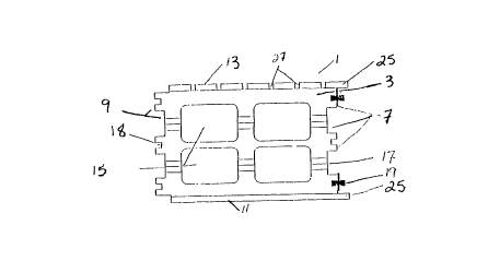
Referring to the drawings, the block of the present
invention is made of concrete and generally rectangular in
shape having an upper surface 3, lower surface 5, end surfaces
7, 9, front panel 13 and rear panel 11 and having one or more
hollow sections 15 in the centre portion thereof as are
commonly found in concrete building blocks.
The ends of the front and rear panels 13, 11 extend
beyond one end surface 7 of the block forming projections 25.
These projections 25 overlap the opposite end 9 of an abutting
block when placed in a horizontal row as shown in Figures 5,
7 and 12. The block may have a front panel and a rear panel
or it may incorporate several layers of panels. Each layer
would preferably be placed so that the ends of each layer are
staggered allowing for an increased area of overlap between
abutting blocks. Shown in Figure 1, the front panel 13 may
be divided into sections by a series of parallel vertical
grooves 27 running the height of the front panel 13. This
arrangement, depicted in Figure 2 and 8 allows for increased
drainage and generally aesthetic purposes. The rear panels
may also have a series of parallel vertical grooves or it may
differ in appearance.
The front and rear panels 13,, 11 also extend downwardly
below the lower surface 5 of the block 1 forming projecting
flanges 29. The front and rear panels 13, 11 are also
recessed below the upper surface 3 of the block 1. This
- 3 -
2 ~ 9zz~~
arrangement allows the lower exteni~ of one block la to overlap
the upper extent of a second block lb when the blocks are
stacked vertically as shown in Figure 6 and 8. The
overlapping arrangement of the blocks la, lb helps to prevent
precipitation from seeping in between the blocks la, lb
thereby substantially preventing moisture from entering a
structure. Conversely, the panels 11, 13 may be recessed
above the lower surface 5 of the block 1 and extend upwardly
above the upper surface 3 of the block to overlap the lower
extent of an upper block when the blocks are stacked
vertically. The projecting flanges 29 and the corresponding
recessed edge of the front and gear panels 11, 13 may be
squared as shown in Figure 3 or they may be angled for all or
a portion of the width of the flanges or panels as shown in
Figure 10. This angled cut provides for an improved placement
of the overlapping edges of the b:Locks.
Referring to Figures 1 and 6, the end surfaces 7, 9 of
the block 1 have channels 17, 18 recessed therein. The end
surfaces 7, 9 may have one or more larger channels 17. These
channels 17 collect any moisture which may enter the block 1
and channel it down to prevent i=urther penetration of the
moisture into the structure. They may also have smaller
channels 18 for receiving and holding mortar 19 and concrete
to help cement the blocks together. The channels 17, 18
extend for the height of the end surfaces 7, 9 of the block
1 in a parallel formation. Shown in Figures 9 to 12, the end
surfaces 7, 9 consist of a single channel 17 between the
projecting flanges 25.
The upper surface 3 of the blocks 1 have one or more
indentations 4 therein. The block. 1 may have hollow sections
15 extending through its height as are commonly found in
concrete blocks. In Figures 1, 4, 5 and 7, four hollow
portions 15 are shown. However, various arrangements may be
utilized such as the one shown in Figure 9. These hollow
portions 15, large channels 17 in the end panels 7, 9 and the
- 4 -
2 l 9~~'7~
indentations 4 reduce the cost of manufacture and weight of
the blocks 1.
The arrangement of the blocks 1 when stacked horizontally
and vertically is shown in Figures 5, 6, 7 and 12. In Figure
6, the lower projecting flanges 2Si of the front and rear
panels 13, 11 of the upper block la overlap the upper edge of
the lower block lb where the front and rear panels 13, 11 of
the lower block lb are recessed. In Figure 7, projections 25
at the end of the front and side panels 13, 11 of the blocks
lc overlap the outside of the end surface 9 of the abutting
block ld.
Figure 8 shows the blocks 1 .in successive horizontal
arrangements forming a wall. The lower flanges 29 of the
blocks 1 overlap the upper edge ( shown in dotted lines ) of the
blocks 1 in a lower row. The flanges 25 also overlap the end
panels 9 of abutting blocks 1 in a horizontal row. The
vertical grooves 27 of the front panels 13 of the blocks 1 are
generally in alignment to provide drainage.
Figures 5 and 12 show the horizontal arrangement of the
blocks 1 at a corner. The corner piece 2 in Figure 4 has one
or more channels 17 in one end similar to the block 1 in
Figure 1. However, its other end 8 .is generally flat and may
have a series of parallel vertical grooves 27 similar to the
front panel 13. A portion 12 of the rear panel 11 is recessed
causing the end panel 8 of the corner block 2 to project
beyond the rear panel 11. This recessed portion 12 has a
number of channels 18 for holding mortar for binding to an
abutting block 1. The recessed pori~ion 12 in the rear panel
11 corresponds in size to the end panel 9 of a block 1 and
receives and retains an end panel 9 of the abutting block 1
in a horizontal configuration. The recessed portion 12 in the
rear panel 11 may be recessed into the block for a distance
approximately equal to the width of the rear panel 11 or for
a larger recess as is shown in Fig. 4. Furthermore, the
portion 12 may include projections extending outward similar
- 5 -
2i~2~~~
to the end panel 9 so that an abutting block may overlap these
projections rather than the recessed portion 12 receiving and
retaining the end panel of an abutting block. This and other
embodiments of possible corner block arrangements within the
scope of the present invention are shown in Figures 11A-G.
Figure 12 discloses these 'various blocks abutting
horizontally. The front and rear panel 13, 11 and end panel
8 of the corner block 2 are recessed from its upper surface
3 and extend beyond the lower surface 5 in projecting flanges
similar to those utilized in the block 1. The projecting
flanges overlap the upper edge of an adjoining lower block 2
when the blocks 2 are stacked vertically. Conversely, the
panels 11, 13 may, of course, be recessed from the lower
surface 5 and extend beyond the upper surface 3 of the block
1.
while the present invention has been described with
reference to preferred embodiments, it will be appreciated by
someone skilled in the art that modifications and alterations
may be made without departing from the scope of the invention.
Therefore, it is intended that the foregoing description will
not be limiting in any way.
- 6 -