Note: Descriptions are shown in the official language in which they were submitted.
21 923~7
'1~7~t'~T. ~D 0~ ~!EllZ ' C. . I '
The present invention fits ln the ~hni ~Al field o~
waste water pot~h1l;7~t~n and sea w2ter i~c~llni7~tion~
~ore yp~ri fi r~l 1 y~ the invention provide6 a ~5Al in; 7i~t~ ~n
system that allows the obtainment of fresh or purified
lo water with an inst~llAtioh oi reduced ~o~OLL~Llon cost
that allows purlfied or desalinated water tc be obtai~ed at
a low enerqy cosOt and without 11 ~t~ nt~n7~n~e
op~rat1 nnc,
r~ or T~
Th-o ~Dc~Jni7J~t~nn o~ salt wJter and the pllr~iC~t~rm
o~ waste ~ater ls convpnt~nn~l ly done by two general
systemO, in other words, the ev~ror~tinr~ of water and
cnllPrt~nn with r~rnn~l~nRation of stean~ Ond filtration of
w~ter, through ~ilters or, in the caOe o3~ reverse osmo8i8
~,A1~ni271tir.n, through 5P~
1~os~11n~7~tion by oOr~osis is u2sed in sea water
potabllization ~quipment in ship8 and in dii~erent coastal
areas, in ~lD~ ni7~ion plarlts used ~o provide the
population and/or agriculture with fresh water.
Reverse osmoOis rl~s~l~ni-~tion implies that the salt
water must be forced through ~ilters or I applying
a ~reat pressure ~approxlmateiy 70 c- , ~r~s) whose
creatlon requires a high energy ~ n , ' lon, a3ide from
expen~ive and relatively complex ~'T~ hi8 ~ar~.ci~lly
30 af~ects large d~ n17~t~t~n plants that supply large
amounts of ~re~h water in ~oast~l areas whoOe ~onstruction
requireO very hiqh inveOtment~ ~nd whos61 ~-int~nAn~e io
complex and costly, which results in, along w~th the aoo~e
mentioned high energy ~on~um~tlon, the hlSJh prlc~ o~ the
3s desallnated water.
21 9~307
In order to overcome the high enerqy c08t, Spanish
patent Es-A-4~8,215 ~IP5rr~hP~ a water ~P~l;ni7Ation plant
by a reverse osmosis hydrostatlc system whlch by means of
60me weLls drilled in the suhsoil, est~hl1shPc a water
5 column whose weight exerts a pre3sure on the osmotlc
modules so that the r~h~n~ nr~n oI~ reverse osmosis is
produced, thus replaclng the impeller pUlnp5 of traditional
plants. Elo~ever, this plant though it reduced the energy
cost o~ the cubic meter of degallnatcd water regarding the
10 energy cost of t~ditional ~ Al~n~7Ation plants, it still
required high energy c06t3.
COEIJ]5C!r 01r 5!1115 1A .
The present invention is used to o~ercome the above
cite~ inconvenlences of conventional ~ Al~n;7~tion plants
15 as well as to reduce eve4 more the energy cost of the cubic
meter of ~IP~ nAt~l ~ater ~Ind the plant construction
c05ts. Besides, another object of the invention is to
provide the Fo~sih~l;ty that the rl~cAl;ni~tion
inst~ t~-~n~ have a substantial flaylhil~ty with regard to
~o operation, ln~t;~n~ r~ PnAn~ and repairs.
D15~!AI3ilD L~o~ OF !1!~; ~ .
a~ i n~ At~ ir. itg title and Z8 defined in the
claims, the present invention refers to a reverse osmo~is
~P.~ ni 7Ati ~ plant whlch in order to create the neces6ary
25 pressure in the reverse osmosis module6 take8 advantage of
the pres~;ure that the weight of an es~h~ i ~hP~ salt wate~
column exerts on said modules. ~he ~iPsAl;n~r~n plant is
located on land. The reverse osmosis modules can be placed
at sea level itself or at a lower level with regard to Oea
3~ level, ~PrPn~n~ on t~e possible ~opoqr~rh~r location of
the plant that r~ prm~ nes the necessary height o~ the salt
water column in order to obtain the required pressure in
the modules.
A main characteristic o~ the ~ n;~tiort plant is
35 that it has an elcvated head tank for the accumulation of
i'
21 923~7
salt water. Said tank allows the ~ 1 rf;~n of a certain
amount of salt water, that i3 pumped during tho3e hours in
~hich the electric rates are cheaper, in such a way that
the plant operates the rest oi the day without needing to
S consume electric energy and the energy consumed for pu~ping
turn~ out to be cheaper. Besides, it makes it possible to
ensure a constant stable pressure on the osmotic module~
upon not ~ rPnrl~ ng on the constant operation of a series of
pumps, such as in the case o~ tr2ditional plant6.
Io On the other hand, elevating the head tank allows the
brine resultin~ ~rom the re~erRe osmosis process to rlse to
a certain height by natural pre3sure without the need o~
any pumping. This produces~ on the one hand, the advantage
that it is not neccssary to include pumps exposed to the
great cor~osive aggresivity of the brine and, on the other
hand, that s2id head tank, upon comprising a water reserve,
allows the carrylng out of ~~intPnAn~e ~nd repair
operations, without having to stop the operation of the
~I qA 1 i n 1 ~ation plant .
zo In a preferred - 'i of the ~ l in~ 7Ation plant
ol~ thc present invention, the po53ible t ro~rhi 5
characteristlcs of the land close to the sea due to the
location and con5truction thereof can be taken advant2ge
of. In other words, one can take advantage of the height of
a ~ountain close to the sea high enough to place water
column6 that exert enough hydro~tatic pre~sure on the
osmotic ~noduLes for ~ n~ ~tion in a plant located above
sea leqel. In thi3 case, the plant i3 built either
substantially inside the Aln with its pipelines
located in wells or vertic~l shafts, or else, it could be
built outside the A~n placing the diiferent pipeIine~
along the profile of the p~n, therefore, ~ inin~
inclined and not vcrtical. In thi~ way the need to drill
v~ry deep wells in the 3ubsoil i~ avoided as well as to
build underground ~1 l Prle~ at said depth that turn out to
. i
.
~1 92307
s
be expensive and co:~tly to ~~int~n
Likewise if the height o~ the mountain does not
suffice to establi~h the entire water column above the sea
surface, wells can be drilled in the gubsoil to house the
pipclines, therefore, part of the water column remains
above the Yea surrace and part remains below it. The water
column can ~ 3o be est~hl ~ Yh~] above the sea surface
placing the osmotic modules ~t thl~ ~ame level and
- 1~ ns the difference of heisJht by means of an
i ~linq pump at the inlet of the osmotic module~.
~err1rrll n7 to another advantageous ~ Or the
present invention thcre are means to generate electr$c
~ergy that take advantage of the r~sidual energy of the
brine, 8ince the brne come~ out of the rever6e o~o~l~
modules with a high pressure although iower than when
entering. The electric energy generating means can be
,~ ri c~l of A turbine coupled to a generator. Said
turbine ls n~oved by the brine that comes out directly ~rom
the reverse osmosis modules or el-~e by the brirle that has
been previoUsly accumulated in a high tank. The brine
rises up to said tank thanks to the residu~l pre3sure that
it has when coming out of the mcdUles.
In this way the electric energy c~ _ tion i~ pumping
can be combined ~rith the electric e~ergy production in such
2s a way that the resulting cost i6 mninul1, either because
the electric energy producod i~ returned to the commerciAl
network in thoge hou~ whe~ the rate s the highest, or
elbe becau~e ~aid g~n~rat~d electric enerSJy is used for the
supply itsel~ of the plant.
Thus, the ~ AI~n~7Atio~ plant of the present
invention in accordance with the above "~n~d preferred
' '' ~ is bA~i~Ally located in a mountain close to the
sea ~t a ~uf~iclent height of about 750 tneters, and the
reverse osmosis module~ are placed at the s~ce level as sea
level, bu~ lding the plant outside or in~ide the mountain.
-~
~ . , , ~,
21 92~7
.
In this case, the plant basically h~s ~:he followinr~
elements:
- a salt water inlet provided with the pumps needed to
pump the water to the high head t2nk:
S - the conduits or E~;rol 1nF.5 needed to transport the ::
salt w~ter, the desalinated water and the brine;
-- an elevated head tank to store salt water and that
h~s a 3peci~ic accumulation capacity;
- prcfera'oly, a hish tank to accumulate brinei !`
- reverse osmosis moduleg with sPmip~ ~hle - rAn~c
located at a level er,ual to sea level;
- preferably, electric enerqy generating mean8
of a turbiIIe coupled to a generatori
- preferably ~ea water pretr~ ~ means at the
outlet o E the hi~h head tank:
- the ~ r; ~ and tunnels needed for accesa and
maintenance of the installations ag well a3 all the
necessary auxillary er,uipment.
The level at which the high head tank ls loc~ted for
accumulation of galt water i~ that il~ which the height of ;
the water column that is sst~hl; ~he~ under said tank i3
such that the pressure exerted by ~aid column turnq out to
be 9~ rJ ~t to produce the ~' of reverse 03mo3is : Y
in the modules.
~5 Like~ise, the level at which the hiqh t2nk i8 located
to A~ te brlne is the 6ame as the maxi~um helsh'c that
the brine is capable of reaching by natural pressure
without the ~eed of pumping.
~n this way, the or~r~f; rn of the plant and the
proces~ to desallnate s~lt water is the rnl1r.~in ~
- The salt water ~rom the ~ea is rrl 1 ~r~d by the salt
water inlet and ls pumped to the head tank. ~his pu~ping
is preferably produced during the hours when the electric
rate i5 reduced. i~
3~ - At the same tlme, the ~alt water is con6tantly
1 . ,.
1'.
- r - - ~ - ~ . . .=
2 ~ ~3~7
comlng out of the elevated head t~nk, being pretreated and
passinq to the ducts or ~i r~l ~ nPq that e~tablish the water
column over the re~erse osmo6is modules.
- As the 1' of reverse 089is is produced ln
S said modules typically 4556 of the flow o~ crude water 1
desalinated ~ater and 55% of the ~low o~ crude watcr in
brine are obtained.
- Said brine rises, by virtue o~ the residual pressure
that it has when coming out of the modules, up to the high
o brine tank (in the case that there is one), where it can be
~ccumulated.
- S~i A~ tly and ~~or~r~ to the need~ of the plant
or the pos~1h;1~ties of retur~ing energy to the r~
system, said brina can be allowed to drop frotl~ said tank
~5 for the purpose of moving the turbine and ~tr-r~7lr~nq
electric energy that c~n be used to meet the needs of the
plant itself or be returned to the net~ork- 5~ se~lu~ 1 y,
the brine is polLred into the sea.
- ~he r?~ 1; n~P~ ter i~ either ~ent directly to the
2Q commercial Water dis~r~ nr~ system or else it can be
accumulated in a tank.
When the ground close to the se~ is not high enough,
the water column can be partially lor entirely) made in
perforations in the ground, in other words, under the level
Z5 o~ sea level. ~esides, as a , 1I t (in the event that
the column itaelf cannot exert enough pres~ure 80 that the
rh~n~ nn of reverse o~mosis is pr~ P~I~ the pressure on
tho reverSe osmosl5 modules can be incre~sed by pumps, that
increase the pressure that the salt water colu~[~ exert~
3~ ~he result of the described process is thAt the total
energy co~t oi~ the cublc meter of desalinated water is
substantially reduced, either by the sel~-g~ r~ nn of
electric energy or by the compensation o~ the dif~erent
electric rates C.,I~-s~ to ~onsumption And to the
35 production and return of this energy to the commerclal
;",
~ . . . . .
2 1 92307
network .
BRlSF ~c ~ OF ~oe FIWR~:8
Figure 1 is a schematic vietJ of a first pre~erred
' '~ of the invention.
Figure 2 is a schematic view of a second pre~erred
Pn~ o~ the invention.
Figure 3 is a ~chematic view o~ a third preferred
' of the inventlon.
Figure 4 is a schematic view o~ a ~ourth preferred
r~o~i~ ' oi the invention.
Figure 5 i8 a ~ection o~ a possible; ` '~~~' of the
~ain pipellnes that hou3es the duct~ or channels to
tran6port the salt water, pretreated salt water and bri~e. I
Figure 6 is a fi~th; ' I of the invention
Figure 7 i a sixth ~ t.
Fiqu~:e 8 is an ~ r of the ~.d~ ~ y ~ VUI~d part of
an~ rrnr~; ng to figures 5 and 7 .
or T~ 1D
~ereinAfter and referring to the figures, a -.
20description is made of four pre~erred: '-`' ' of the
invention.
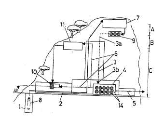
Just as one can see in figure l, the ~ Alin;~t~n
plant ;~c~-nr~n7 to a first: ~~ ' has the reverse
osmosis moduleg (4) with their COrl~ r~ ~Am~r~
membranos (14), located at the same level ~s sea levAl
The plant can be bullt taking advantage of the suitable
~h~r~tAr~ ~ltic6 zl~s to the height of a ~e~r~rh~ ~l feature
clo6e to the sea, 6uch a~ a -Air~ ln such A way that
the salt water column ~3~ that is e~tAh~ her2 over the ~-
reverse osmocis ~odules ~4~, remains above sea level and 1;
the reverse osmosis modules with a height such that thelr
wcight exert~ enough pressure on the modules 30 as to
produce the rhAr~nnlpnon of reverse osmo~is. ~:
The ~iAc;~l~n~ tion plant has a salt water inlet ~
and some pumping means (8) to pump 2alt ~ater from said
i,',"
~. .
2~23Q7
inlet ~1~ to a high head tank (7~ through some salt w2ter
ducting means (2~. ~rom said head tank 17), the salt ~ater
is passed through some pretreatment mean~ ~9~ that
condltion the s21t ~ater. Then, the calt water column ~3~
5 is es~h~ over the reverse osmo5is modulec ~4) that
are located close to the bottom end (3b~ of the salt water
column ~3~. The height o~ the salt water column ~3)
measured ~rom the pretreatment means ~9) to the reverse
osmosls modules ~4) corresponds ln figure 1 to the sum of
o levels B and C. The pres~ure exerted by the welght of this
water column ls enough so as to produce the p~lr- of
reverse osmosis, by mean~ o~ which one part, typically 559~,
of the salt water 11lL,~ in the well ls con~erted into
brine that is loaded with ~11 the salt8 pre~ent in the salt
~5 water and it comes oUt o~ the reverse osmosis modulQs (4)
at a high pressure. The 1, 1n~r~ gS% UU~L~ JU~d~ to
desalinated water that come3 out of the reverse osmosis
modules (~) at a lower pressure.
ThQ brine 1~ led through the brine ductlng means ( 6~
2Q up to the brine tank ~11) or directly to the electric
energy ge~erating means (lC ) . Since the brine has a high
pressure when coming out of the module~ ~4), it is capable
of riging by natural pressure and ~ithout the need of
pumping to the brine tank (11), that i9 found ~t level C.
25 The brine stored in said brine tank ~11) can be used later
to ~nerste electric energy by means of el Qctric energy
generating means ~10). Likewi~e, th~3 brine can be directly
passed from the outlet o E said osmosis modUles to the
electrlc enQrgy gPn~r~nq means (io). The orine i~ then
30 returned to the sea.
The ~cAl;nAtp~ water i~ led through the ducting mQans
~5) to a tank ~not 6hown) or directly to the commercial
water sygtem.
Nûwadays, the pressure that the reverse osmo~l6
35 module~ require 19 about 70 kg/cm. To achieve this
!
!
i . ~ A .' _ -- . . r . .. _
2 1 9~3~7
.
pres6ure the helght ~+C of the water column (3) has to be
about 70C m. There~ore, the pretreatment means ~91 would
be located at a helght of 700 m. The elevated head tank
~7) would remain located with regard to the pretreatment
5 means ~9) and the top end 13a) o~ the salt ~ater column ~3)
at a helght A of 40 m., the total height thereof beLng
(A+BIC) with regard t~ the rever~e osmosis modules equal to
740 m. With this ~rrl- ~ t. of heights, the brlne has
~hen coming out of the reverse osmo8is modules, a pressure
10 of aoout 69 kg/cm2, which implies that the brine can rlse
without the need of pumping to a helght C of 640 m., where
the brine tank ~ll) ib located.
The r;o~ n~ 7:~t~ 1 pl~nt cz~n be built in such a way
that the ~ 1 At~ rn capacity of the head tank i5
15 equlv21ent to 2~3 Or the total s~lt water treated daily.
The brine tank would have an accumulation c~pacity in
arC~r~3An~-e with the need~ of the generation of electric
energy. In thl~ preferred pmhorli the capacity could
r..~ r; to 5~6 of the total brine generated daily.
~o Therefore, the op~r~t~rn o~ the plant ln accordance with
this first ~r~-f~rrP~ could be the ~ollowing:
the salt water i8 pumped to the head tank when the electrlc
rates are reduced. ~he hrine is ~ feA in its
corrPsr~n~ g tank u3ing it later on to move the electrlc
25 energy g.-~rAt ~ng means, returning the energy generated to
the commercial network or else using it to feed the pumps
and auxiliary equ~_ of the plant . I ikewise, the brine
can be used directly when it comes out of thc r:everse
osmosi~3 modules ~ 4 ) to move the electric energy generating
30 mean3 without pre~7iously accumulating it in the tank.
Figure ,' illustrates a second pre~erred - o~
the rl~s~l1n17-tion plant h~tc~lly identic~ll to the ~ir~t
~/i-q t, in which the reverse osmosi~ modules ~4) are
locate~ un~er the level of sea level. ~here~ore, part of
35 t~e salt water co~umn ~3) will be under sea level and part
!~
~, .. . . . .
~ 92~ G~
11
of it wlll be abo~e 3ea level. This ~ ;r ~ is suitable
~hen the rh~r~ct~ tics of the geo~r~rh;c fe~ture do ~ot
suf~ice to re~ch the nece8sary height above sea level.
As th~ reverse osmosis modules ~4) are below ~ea
5 level, it is necessary to raise the (;P5R1 1n;ltpr~ ~ater to
the surface, which is achieved by pumping means (12). In
order to feed these p~;n.ping means (12) the electric energy
generated by the generating means ~lD) can be used.
Figure 3 i_lustrate~ a third preferred ` t of
the invention. In thi8 ~ the re~rer3e 06mosi3
modules ~4), ~ust like the ~ of figure 1, are
located at the same level as sea level, but the hei~ht of
the salt water column ~3~ i~ lower than that level whose
Weight exerts enough pres~ure 30 that the ~ of
- 15 rever6e osmo~ls is rro~ r~d To achieve the total
necessary pressure in the module3, pu~ping means tl3) that
provide the ~; ff~rPn~e of pressure between that which the
water colu~n produces and the requ$red pressure, are
included.
lo In this - '~ , there is no brine t~nk ~11),
causing the }~rine to pass directly fro~ the outlet of the
modules r4) to the clectric energy ~n~r~tin7 means ~lO).
which in tUrn feed the pumping means 113~.
In figure g one can ~ee a fourth preferred -~i
essentially ~A~ntic~7 to the ' 'i - shown in figure 2
and that is ~l~fff.r~nl as it includes an ~lv~ v~ d ta~J~
~15) for ~c~s~7in~t~ wat2r Said tank is located at height
D that is ele~ted with regard to the reverse 03mo~is
modules ~4) Said heis~ht D i8 such that the de~alinated
3~ water can reach said tank without having to be pumped
thank3 to the pres3ure that it ha ~ when comlng out o~ the
modules . For ~n input p~ ,3;,uLe o~ 70 kg/cm' in the
moduleg, the pre~3ure of the desalinated water tends to be
from ~ to 1 kg~ 2, rrhi~h ~nplle~ that height D at which
35 the tank ~15~ is located i8 aoollt lO to 2~ m.
i '
21 9~3~7
.
1~
The ~Al;rAtP~ water can be ~ ltPrl during a
specific period of time ia order to pump ~t to the sur~ace
later on.
The plant o~ the ~ of f igure I as well as the
5 plant of the '' ~ o~ figure 3 can be built out~lde or
in~ide the geographic ~eature. In the event that it 18
built ln~3ide, the plant would include a serie6 of tunnels
or rJAll~r;P~ ~he salt water ducting means ~2), the brine
ducting means t6~ and the means to establish the water
10 column ~3) could be bullt, as one can see in ~igure 5, wlth
plurallty of ~c5~r~tl /~1 y vertical ~Pl ~rPS (16~ placed
in the inside periphery of a main ~si~ntiAlly vertlcal
pipellne tlt~ with a diameter larger th~n the previous
ones .
Likewise, i~ the const}uction iY outside, the
di~ferent rlr~ l 1n~e~ and the ducting l:Leane can be placed
inclined following the pro~ile of the rue~7r~rhlc Eeature
where the pl~nt is located.
Figu~e 6 6hows a fi th ' .` - of the present
invention. According to thi~ t, the rlDg~l;ni~J~t;nn
plant likewi~e, ,_ ~e~ some first ~ells (104~ that
receive ealt water f rom the ~ea . In ~he b~se of these
~iirst wells (104) there ~re batterieB 0~ rc~mlI~ -~l"
-~ of the type adequate to carry out the 1'
25 of re~er~e osmoals. While the wells ~104) ~re full o~ salt
water, the pl~f- - of reverse ossis $s produced by
means of whlch oae part, tyoically 5596, of the ~alt water
intro-l--rfd in the well is conver;:ed into liguid wastes
~"backwater" or ~ri~e) that is loaded with all the ~alts
30 present in the ~alt water aDd it comes out of the n~
system (l~S) at a h$gh pres/!;ure, ~or exampl~ about 68 Atm.
in the event t~at the water column over the ~S (lOS)
has a height o~ about 702 meters ~being based on a eea
water density o~ 1.o3 gr/cm..3, creating a pre~3sure of 70
35 Atm. in the b~se o~ the wells ~lOg) where the ~
,
2 1~3~1 1
13
(105) are located.
The lnin~ 45% o~ the 10w of sa7t water introduced
in the wells ls co~Ve ted into totally salt-free drinking
water with a residual pressure that iB rel~tively low at
S the outlet, o~ 1 to 2 At~. having a water ~olumn of about
702 meters over the membranes ~105).
This ~eans that éxactly at the 3ame rate aæ the salt ! `
water :Erom the 3ea and once subjected to the same
pretreatment 6ystems (116~ as in a conventional plant, the
lOwater i9 iIl~LodUCed into the first wells tlO4), almost half
o the water is ronvYrted into ~resh water, ~hile the brine
rl6es, taking into account the density thereol~ ~30me l.Q6
gr~Cm~ in the event that the salt ~ater introduced in the
vertical wells (lOq) is normal sea water~, by a second
l5hat"ery of wells (1091 bullt next to the first wells ~104)
that receive the salt water, at some 646 ~. ~as the lntake
~irst wells ~104) ha~re a depth of 702 ~) over the oUtpUt
le~Tel o the ~embranes ~105). L
For the pUrpose of avoiding the pumping of the brine
2~~ro~n the static level that it reaches in3ide the second
wells ~103) up to the sur~ace And th~r~lf~re the enQrgy cost
that this pum~ing would invol~re, a~ well as thQ cost it~ell~
o~ some very expensive and delicate pump5 as brine has to
be pumped, in the preferred _' : sho~n in ~igure 6,
2s~he de~ice is designed in such a way that the brine reacheæ
the drain through the mouth of the sQcond well~ ~lO9) of
l:he ~cond battery by natu~al pressure. In order to
~chie~7e this ef~ectl it is necessa~y to increase the ~oa~l
in the mouth o the irst salt water i~ction wells ~134),
30and once the den3ity of sea watQr is considered, b~ 63 m.
Eor this purpo~e, the A~cnlin1~t1nr plant ha3 been
provided with a head tank (117) th~t once the diferent
it~5 o~ the 1ulds that we are dealing with as Well as~
the load los~e5 produced in the systel[- are considered, it
35would be placed ~ome 70 ~. above the level o the mouth of
2~ 9~7
. ~
lg
the wells, for the purpose of att2inlng a constant pr~ssure
in- the ~ JAnf.~ ~05~, which is ~llnrli ~1 for the good
operation and duration thereof, at the same time that it
achleves th~t the brine reach~s the su~face without any
s type o~ pumping. ~ogicAlly, upon using the head tank ~117)
placed at a certain height with re~ard to the surface, the
depth of the first wellO (10~ that receive the crude 3alt
water can be reduced in corracpnnr?l ~re with said helght.
The sea salt water, once subjected to the pertinent
1~ pretreatment in a l~retreatment system ~116~, i8 pul:lped by
pumps ~118~ to the h~ad tank ~}17~.
The ~resh water tha~, typicAlly, in the case r~psrr;hnd
could cr rr~ror~ to 4596 of the total crude water, comes
through the ~ at a residual pressure of 1 to 2
~tm., which r~r~rosDntq oetween 10 and 20 m. of height over
the output level of the membr2ne 3ystem. From this depth,
the water is pumped, through a third well system (107) to a
sur~ace tank ~110), that remaln3 ready for the distribution
thereo~ .
Arr-orr~i n~ to a sixth ` - o~ the in~rentlon,
shown in figure6 5, 7 and 8, the first wellsa (104~, second
wells (109~ and/or third ~107~ wells for salt water, brine
and de3alinated water, respectiYely, can be housed in8id~ a
main well ~19~ with a larger diameter. The flr~t wells
tlO4), second wells ~109~ and third ~107) wells can, in
this case, by ~ d by r;ro~ locAted in 3aid maln
well (19) and/or by inside vertical walls o~ the ~irst well
(19), by means of which ducts corr~sr~n~in~ to 3aid first
~ells ~104) second wells ~109) and thlrd ~107) wells are
f ormed .
~n :~igure 7 one can ~ee, ~ Ally, the
~3~.5;~1~n; r~tion plant according to a sixth ` t. This
corresponds essentially to the r - i t illu6trated in
~igure 6, but it includes the main well in which the first
35 wells (la4), second wells llO9~ and thlrd (107) well~ are
located. ~his way o~ making the ~tructure of the ~ells can
~acilitate the pr~ ri~ tion of the wells, with
the ~llh~ nt reduction o~ the costs involved. ~n f lgure
7, on~ can also see an under~rount riP~I inA~ed ~ater tank
5 (115)
In figure ~ one can see a perspective vie~ of an
' '; ' of an underground part of the present in~ention
according to the c ' ' ~ shown in ~igure 7 . A larger
well (119) r; ~P~ a first well (104) and ~ ~econd well
lo ~109), separated by a vertical wall that divide~ the inside
of said larger well ~19~ into two The first well (10
and 8econd ~109) ~ell are c ;r~ted by their bottom part
with a ~lps~lln~tion chamber (112), inside o~ which the
S~r~ hl e filters or ` ~ 105) are housed. The
~5 semirP hlP filters or ' - ~105~ are, arrnr~l;ng to
this ' J-'l L, placed boetween a first PcYPn~ y
hori~ontal duct ~123) that ~~ ;r~tP~ with the first well
~104) and an ~senS~ y hr~r~z~ l duct ~124) that
tes with the second well ~109) . The ~P~Al ~n~ 7~tlon
2a ch~mber 1122) has a dP~Al in~ltPr~ water outlet that
1 r;~te5 by mean3 of a duct tL25) with ~ l~ourth well
(126~ and, through this, with a de6alinated pumping chamber
~121~ that ~ ~rate~ with a ~eries of l-n-lPr~r~l-n~
r3P~al i natP~ water tanks (115) . The ~ Ated water
pumping chamber ( 121 ) may be locat~d ~t a certaln height
(for example, 15 meters~ above the ~ "AtP~? water oUtput
level of the ~ilters or - r~nn~ (5~, given that the water
come3 out o~ them under a certain pres~iure and, therefore,
it can rise up to the 8~1 in~tP~ water pumping ch~mber
3a ( L21 ) ~ithout the neet of pumpin~ . E rom the underground
desalinated w~ter tank~ -(115) and the pumplng chamber
(121), the desalinated water i~ pumped to the sur~ace
through ducts o~ ~econd wells (107), housed inside the
fourth well (126). The ~ourth well (126) can ~1~30 hou~e a
3~ lift (112~.
~ 9230?
16
The energy production cost of a cubic meter o~ sur~ace
drinking water ready for l~ .Lt. dis~r~h~ltlnn can be
calrulated for exam3?le for ~ plant ~r~or~li ng to the second
preferred ` ' ~ o~rr~he~ above and with a production
o~ 200, 000 m3/day. This ~Alr~7lal irn is based on the
- -rr;~l equipment existing nowadays.
With the 3uitable rlt~ ~inn~ oEi the underground ~resh
uater tank ~115) and of the head ~2nk ~117), enough water
can be stored in these tank8 80 a~ to pump the salt water
1~ up to the head tank (117) and the pumping the ~resh water
to the surface can be done malnly at nlght, whlch implies
the rQs~;hil~ty of using night Plort-ir~ty rateS. The
plant production during the day can thQre~ore be done
~c~Pnti~lly without any pumplns given that the liquid
wastes go up to thQ sur~aCe through the second wells ~lO9)
~ith the need o~ any pumping.
Ba~ically, one can calculate an energy cost of 0 . 7
Kw.h co~ d1 nç to the ~onsumption o~ the pumps thzt in
the ~ir&t nrPr~t1n~ stage take the water from the sea and
2~ by means of a ~iltering system ~ree lt o~ impurities. This
n~ I.ion is the maximum, th~t nowaday~ and for the worst
filtering rnn~;tinr~ rn,r ~L ~,.lL to a classic pl2nt. In
addition, a .u..~ ~ L;nn o~ 0.50 Xw.h to li~t all the crude
~alt ~ater to the head tank i:~ rJllr~ tt~
Finally, one can r~r~ te a C~-L1~1 ~nr of 2.01 E~.h
to raise de~alinated drinking ~ter from a depth of 6~0 m.
to the distrih~J~io~ tank.
The total ,_ui, . i on there~ore corresponds to 3 . 21
~w.h.
~resently, i~ a con~entional ~Pc1.l lni ~tion plant and
due to the need to pump 100 P~ o~ the crude ~ater through
the membrane system at a pressure of 70 Atm., a minimum ls
rnn 1, for the 6ame ~iltering condltions and cnn~ oring
the maximum recovery of energy that can be obtained in the
35 turbine pumps t~at are ronvPnt~nn:.lly used, the
2 ~ 9~3~7
corr~cp~n~ n~J tota~ consumption amounts to 4 . 6 Kw. h .
A3 one c2n see, the energy 8avings that i3 achieved by
the present invention is 3u}~stant$al.
~o
~5
3s