Note: Descriptions are shown in the official language in which they were submitted.
CA 02192560 2006-O1-26
1
SMOKING ARTICLE
This invention relates to smoking articles
and in particular to an enclosed smoking article.
The object of the invention is to cut down on
or prevent entirely sidestream smoke particles escaping
into the ambient atmosphere thus eliminating one of the
major causes of annoyance to non-smokers. We aim also
to retain the ash which falls from the rod - another
cause of annoyance. The structure also allows for the
safe disposal of the article if it is self-
extinguishing or is held to a low external temperature.
This is achieved according to the invention
in that the rod of smokable material such as the
tobacco rod of a cigarette, cigarillo or cigar
(hereinafter "tobacco rod") is mounted within and
spaced from a wall which is of a closable container
which is at least partly porous. One end of the rod is
accessible for smocking.
According to one aspect of the invention, a
smoking article has a smokable rod with two end
portions and an intermediate portion and mounting means
on one of the end portions (hereinafter called the
mouth end) mounting a wall of an enclosure to surround
and be spaced from the intermediate portion and the
other of the end portions of the smokable rod. At
CA 02192560 2006-O1-26
2
least part of the wall of the enclosure is porous to
permit combustion of material of the smokable rod
within the chamber formed by the enclosure, with the
end of the one end portion of the smokable rod being
accessible. The mounting means permanently mount the
wall and maintain the smokable rod spaced from the
wall. The wall provides inside a protective tube at
least one of heat dissipation, heat insulator and
adsorption functions.
Preferably, the wall is a cylinder in which
the smokable rod is mounted coaxially with its mouth
end flush with or projecting from one end of the
cylinder and permanently mounted there by the mounting
means; at the other end of the cylinder may be a
closure. This may be removable and/or may allow access
for lighting the smokable article. When the mouth end
projects from the end of the container, air may in
appropriate cases pass directly from ambient to
ventilation of the filter.
The smoking article will preferably be
filtered. The filter assembly may be preassembled to
the smokable rod and be mounted by mounting means to
the wall or may be attached to the wall beyond one end
of the smokable rod and of the container. The mounting
means may themselves be permeable, e.g. be filter
material, or may be impermeable such as for example
WO 95/34226 . - PCT/GB95/O1Z99
21925b0
3
closed cell foam.
There may be a plurality of layers in the~wall
of the sheath or container and particularly when
cylindrical in the cylindrical wall, these layers
having various functions. However, at least one such
layer and preferably all such layers will desirably
bear accessibly one or more of a catalyst, a heat
insulator or an adsorbent such as activated carbon. so
as to act upon semi-volatiles and vapour phase
- components of the sidestream smoke. Any of these
ingredients may have more than one of those capacities.
The outermost layer (the sole layer when only
one is provided) will normally be of a stiff but porous
paper.
There may be a heat-sensitive indicator band
along the outermost layer so that the smoker can see
that the smokable rod is alight and how far the burning
area (the "coal") has progressed.
One or more of the layers will preferably be a
heat insulation or dispersant layer, e.g. a fabric
treated with burn-retardants, or metal foil, wire mesh
or metal or metallised fibres.
WO 95/34226 PCTlGB95101299
2192560
4
The smokable rod may be self-extinguishing,
this being normally provided by a band of paper
incorporating a burn-retardant chemical surrounding the
smoking material at or adjacent the mouth end, or
placedon the inner wall of-the container.
The smokable rod preferably has a wrapper
formulated (as is known per ae) so as to cut down on
the amount of sidestream smoke generated.-
The end cap of the container may be formed; by
a disc ofpaper secured-across the end; by crimping the
end of-the container; by providing a comparatively
rigid end cap which plugs into the end of a tubular -
such container;- by a permanent end cap having a
closable aperture in it; or the aperture may be
closable upon being heated, for example being lined by
an intumescent paint.
The purpose of a removable end cap or of an
access aperture is to allow for ignition of the
smokable rod inside the container; alternatively, the
container may be permanently sealed by a non-
a
combustible material such as a fibrous material and the ,
tobacco rod be ignited by for example electrically or
WO 95134226 PCTlGB95/01299
2192560
by impact on a small detonator such as a non-safety
match head.--When the seal is a fibrous non-combustible
material, ignition of the free end of the tobacco rod
may be by a gas flame striking through the seal when
the two are in contact.
The filter of the smokable rod can be
ventilated and by regulation of--thecomparative
permeability of the filter and of ita mounting means in
the container, together with ventilation of the
smokable material portion of the smokable rod if
desired, it can be determined what proportion of the
smoke from the chamber is drawn by the smoker to be
mixed with that drawn direct through the filter.
Particular embodiments of the invention will
now be described with the accompanying drawings wherein
Figures 1 to 6 are respective diametrical
sections through first to sixth embodiments; and
Figure 7 is an end view of an embodiment.
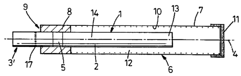
In the embodiments shown in Figa 1 to 4 a
filter cigarette 1 is mounted with one end (free end
13) and an intermediate portion l4 of its rod of
smokable material in a container-6. The cigarette is
WO 95134226 PCT/GB95/01299-
2192560
6
thinner and shorter thaw a conventional cigarette being
for example 4 to 6 mm, usually 5.4 mm in diameter'(as
against the conventional 7.9 or 8 mm) and e.g. 60 to 90
mm, usually 72 mm, in length of which length e:g. 30 to
70 mm, usually 45 mm, is the tobacco rod 2 and e.g. 10
to 3o mm, usually 27 mm, the filter end portion 3.
The rod ~ is surrounded by the container 6 the
wall--7 of which is a-hollow cylinder and of-which the
axis 4 is coaxial with that of the rod. A mounting
block a on one end. of the-rod holds the wall 7 spaced
from the intermediate portion-14 and other end 13 of
the rod 2_ - The diameter of the container will .
preferably be that of a conventional cigarettenamely
7.9 or--S mm and also its length will preferably be that
of a conventional cigarette L70 to 120 mm).
The tobacco rod 2 is of conventional material
for a "slim-line" cigarette and wrapped with
conventional cigarette paper or paper of a type, known
per se, adapted to-cut down sidestream smoke. The
filter 3 is also conventional and may have any suitable
filter material and may be a single or multiple-type.
It is enwrapped by a conventional plug wrap and united
wo ssrsa2zs
219 2 5 6 0 p~~GB95/01299
7
to the tobacco rod by an overwrap.
Adjacent the join between the tobacco rod and
the filter there is a band 5 of non-porous paper which
has the effect of rendering the cigarette self-
extinguishing.
In the first embodiment the container 6 is made
up of a single layer of stiff but porous paper in the
form of cylindrical tube 7. The filter 3 of the rod
2
in such a way that its mouth end is accessible through
the end 9 of the container formed by one face of the
block 8 and can be drawn on by a smoker.
on or accessible from the inner surface of the
tube 7 are particles 10 of adsorbent materials such
ae
activated carbon or zeolites. There is an end cap 11
which as shown is also of stiff but porous paper. It
is however only necessary that part of the container
be
porous-so for example the tube 7 could be non-porous
if
the end cap 11 is porous and vice versa.
It is seen that the rod 2 is mounted so that
its intermediate portion and one end are free of the
walls of the container and a chamber 12 is formed
around it.
WO 95134226 PCTIGB95101299
2192560
8
To light the rod the end cap 11 is removed and
a match or the like applied conventionally to the'free
end of the rod. Once it is burning the end cap is
replaced. Alternatively the end cap may be permanently
secured and internal means of- ignition such as--in -
particular a small chargeof a detonator such as a non-
safety phosphorus match mixture may be provided to
ignite the free end of the rod.
When the smokable material is smouldering (i.e.
not being drawn on by the smoker) sidestream smoke is-
contained in the chamber 12 and no particulate material
should be able to-escape from it. Some volatiles may
penetrate through the porosity of the container wall
but many of them, as well as-the semi-volatiles and the
particulates should be adsorbed by the material 10.
When the smokable rod is drawn on by the smoker
there is a conventional flow.-of_smoke through the
filter 3. In these embodiments, if the block 8 is of a
porous material the smoker-may also draw some of the
sidestream smoke from the chamber 12 and the relative
proportions of the two smokee drawn can be adjusted by
the relative porosity of block 8 and filter 3. If the
WO 95134226 PCT/GB95/01299
219250
9
block 8 is impermeable, some sidestream smoke may be
drawn back past the coal and through the rod 2 and
filter 3
The spacing of the tube 7 from the rod 2
provides heat insulation so that not only does the
assembly cut down on sidestream particulates but may be
able to be rested on an ordinary surface while the
cigarette is smouldering. However in the third
embodiment, to be described, means are shown which will
greatly increase the efficiency of the heat insulation
effect.
Figure 1 also shows how the filter 3 may be
ventilated ae at 17 so as further to allow adjustment
of the ratios of sidestream and mainstream smoke drawn
by the user.
Figure 2 shows a modification wherein a
container 15 has a tube 7 internally coated by
adsorbent 10 as before and also as before the cigarette
1 is mounted by a block 8 to be accessible at one end
of the tube.
a Here however the closure cap is a moulded
plastics plug 16 which the user fits into the end of
WO 95134226 PGTIGB95101299
2192560
. 10
the tube 7 once he has lit the cigarette. The plug 16
need not of course be entirely of plastics material but
may be for example a ring of plastics bearing a web of
paper, which may be porous, across its central void.
Figure 3- shows the third embodiment, wherein -
the container 20 has a plurality of wall layers. An -
outermost is a protective tube 7 of stiff=paper the
internal surface of which may or may not have an
absorbent layer such as 10. Within this and preferably
narrowly spaced from it is an-inner tubular layer 21.
There is also provided a third layer being an
innermost layer 22. If paper 7 is porous then so will
inner layers 21 and 22 be porous.
Adsorbent material 10- such as activated carbon
or zeolite is accessible from the inner surface of the
innermost layer 22 being on that layer or on layer 21
or tube 7. Layer 21 is a heat insulating layer being .
for example filled with heat insulating material or
being reflective e.g. due to inetallisation. Layer 22
is a heat distributing layer having for example
metallic such as a perforated foil or--a mesh or
metallised fibres laying-within itor upon it
WO 95/34226 PCT/CB95I01299
2192560
11
preferably generally in the axial direction. The
metallic fibres when heated may have a catalytic effect
4
upon the vapour phase components of the smoke. if at
least one but preferably both of-layers 21 and 22 are
provided there is less need for-a-maJor air gap between
the rod 2 and-the outer wall 7 while maintaining a very
adequate degree of thermal insulation (for example the
temperature of the outer wall will not exceed more than
150°C, preferably being in the range 60-80°C).
The cigarette 1 is mounted in a block 23
analogous to block 8 and layers 22, 21 and 7 are spaced
therefrom and from each other by comparatively thick
adhesive layers 24, 25.
There can be a removable end cap such as 16 or
as illustrated. here the papers of the three layers 7,
21 and 22 are brought together at 26.
They may be permanently secured together there
e.g. by crimping or adhesion or may offer an aperture
for temporary access to the free end of the cigarette
to allow it to be lit, thereafter being closed together
either by the user by a clip or band or by for example
the application of a layer of-intumescent paint 27 to
W O 95134226 PCfIGB95101299
2192560
12
the relevant region of the innermost layer which swells
to seal the aperture under the influence of the heat
from the rod. It is clear that these expedients, as
well as the use of multi-layered walls, are applicable
to all embodiments.
To indicate to the user that the cigarette has
remained alight, and how far the "coal" has progressed
along it, a strip of a heat-sensitive colour-changing
indicator material may be applied along the outermost
wall 7 of any embodiment.
Further embodiments are seen in Figures 4, 5
and 6.
In the embodiment of-Figure 4, the cigarette 1
of the embodiment of Figure l has in effect been
shifted outwardly so that its mouth end 3' projects
outwardly beyond the end wall 9 of the container. As
shown, ventilation holes 17 are free--of that end 9 and
so when the smoker draws on the cigarette ventilation
air will be drawn from the ambient atmosphere.
Sideatream smoke from the chamber 12 will be drawn
through the smokable material rod. ,-
In the embodiments shown in Figures 5 and 6 a
WO 95134226 PGTlGB95I01299
I3
tobacco rod 2 is mounted in a container. The tobacco
rod is thinner than in a conventional cigarette being
for example 4 to 6 mm, usually 5.4 mm in diameter (as
against the conventional 7.9 or 8 mm) and 30 to 90 mm
in length.
In the embodiment shown in Figure 5, the filter
3" is, in effect, between the end wall 9 of the
container and the mouth end 3"~of the cigarette 1'. It
has in this example a multiple filter structure with
filter material bands 31,32 sandwiching a cavity 30 in
which may be positioned adsorbents or flavour modifying
materials, such as e.g. sepiolite or carbon.
The rod 2' is mounted within the container by a
block 8' combining the functions of annular mounting
block 8 and extinguishing paper 5.
In any of the embodiments so far disclosed and
described, the absolute and relative lengths both of
the mouth end structure of the container i.e. that
occupied by mounts 8,23,5' and of the chamber can be
modi~ied_ -Figure 6 shows one such possible
arrangement, where the annular mounting block of any of
the previous embodiments extends for (for example) 40
W 0 95134226 PCT/GB95101299
219 2 5 6-0-
14
mm from the end 9 of he assembly, the chamber.
extending for example a further 60 mm, giving a total-
length to the article of 100 mm. The expedient of -
lengthening the block or other inert portion 8 (or for
example 23 or 5.') is that the smoker has more space
within which to handle the cigarette without running -
any risk of coming in contact with heated surfaces.
Figure 7 is a cross-section through, in
principle, any of the embodiments previously described
showing how any could have a multi-layer wall 33,34,35,
such as layers 7,21,22 of Figure 3, spaced by the
chamber 12 from the smoking-rod 2.- These layers maybe
separately assembled but may be preassembled as a
laminate before the formation of the container or
sheath.
To summarize, in a preferred embodiment, a
smoking article with a tobacco rod shorter and thinner
than a conventional tobacco rod is used to reduce the
quantity of heat generated upon smoking and also to
reduce. the quantities of sidestream smoke components
generated.
The tobacco red has a wrapping of a cigarette
W O 95134226 PCTlGB95101299
i
- 2192560
r paper which is preferably a fast-burning cigarette
paper selected to minimise the risk that the cigarette
will self-extinguish when smouldering. This rod is
surrounded by a container which is a hollow cylinder
5 (7.9 or 8 mm diameter) and of which the axis-is coaxial
with that of the cigarette.
The filter is of a conventional type with the
addition of an adsorbent to reduce the vapour phase
fraction of sidestream-smoke components which in use
10 may be drawn through the cigarette wrapper or through
the "coal"
The join between filter and tobacco rod is made
by overwrapping with a non-combustible paper to render
the cigarette self-extinguishing.
15 - The material of the container wall has a low
porosity and contains activated charcoal to reduce the
vapour phase components of the sidestream smoke and the
material also includes a mineral filler to provide
thermal mass to reduce the temperature of the cylinder
wall to less than 150°C, preferably less than 120°C and
most preferably to less than SO°C.'
..., ..